In the modern semiconductor ecosystem we are seeing rapid advancement in technology breaking past once perceived limits; 28nm, 20nm, 16-14nm, 10nm and we are foreseeing 7nm now. Double and multi-patterning are already being seen along with complex FinFET structures in transistors to gain the ultimate advantages in PPA from these technologies. In order to realize these technologies in actual designs, it’s utmost important that EDA tools move in tandem with such technologies manifesting their complex rules and constraints into the tools and methodologies which can be used to develop designs confirming to these technologies. As we move down the nodes, it becomes increasingly difficult for the tools to adapt to these complex technologies, thus adding a lag between the technology and tools.
I am extremely impressed with ANSYScollaborating with multiple foundries and making their tools compliant with most advanced technologies to date. A few months ago, I had blogged about Intel’sannouncement on the availability of their production proven reference flow for power, electromigration (EM) and reliability signoff using ANSYS simulation solution (using RedHawk, Totem and PathFinder) for Intel’s 14nm Tri-Gate process.
Read Intel & Ansys Enable 14nm Chip Production for more details.
Today, it’s yet another pleasure to write about TSMC’scertification of ANSYS tools solution at advanced nodes and ANSYS’s valuable participation in TSMC OIPwith a detailed presentationby Norman Chang, VP & Sr. Product Strategist at ANSYS. Before I talk about the presentation and how ANSYS tools handle the complexity of advanced node technologies, let me talk about the certification and some of the key points about ANSYS and TSMC partnership.
ANSYS was conferred with “Partner of the Year” award by TSMC. As a result of the intense collaboration between ANSYS and TSMC, ANSYS’s RedHawk and Totem are certified for TSMC 16nm FinFET+ (N16FF+) technology for static and dynamic voltage drop analysis, EM verification and thermal reliability. TSMC 16nm FinFET technology provides much improved PPA over its previous generation. At present, TSMC certified these tools with its V0.9 DRM and SPICE models, and V1.0 certification is on track before this year end. The collaboration is continuing further to enable designs at TSMC 10nm (N10) process technology. With N10 specific tool enhancements implemented, customer can use ANSYS tools to start their designs in TSMC N10 technology. Read the press release for full story.
Coming back to the presentation which was focused on thermal reliability of designs using FinFETs and 3D-IC designs, it provided great visibility on how minutely ANSYS tools handle physical effects at these nodes and the robust process used in the flow from chip to system and system to chip.
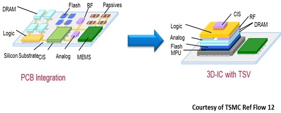
With increased gate density in 3D-IC and less open space for thermal distribution, the thermal effect gets enlarged, and that is compounded with higher drive strength devices such as FinFETs at 16nm. This mandates checks for advanced reliability and thermal impact with consideration of chip-package co-design to be accurate at 16nm; these checks are in addition to other checks such as ESD, power/signal EM, leakage, static and dynamic IR and others applicable at older nodes. The TSMC N16FF+ certified RedHawk and Totem elegantly handle complex EM and ESD rules, unique metal architecture and enhanced modeling of vertical resistance, double patterning and dummy devices. The resistance is correlated including middle-end and back-end layers.
The reliability signoff covers a large set of rules checking into Connectivity (Grid Weakness and Static IR), Reliability (EM, ESD and Thermal) and Power Noise (DvD Noise, Low Power and Impact on Timing). For each of these areas, multiple checks are performed; for example, in case of connectivity, cases such as missing vias, power/ground balance, resistance, IR drop, high power density etc. are performed.
As high temperature accelerates EM (which causes gradual displacement of metal atoms due to high current density) limiting allowable current density, the on-chip maximum temperature must be accurately estimated and controlled.
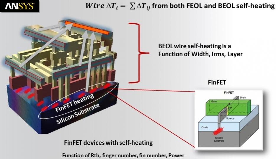
FinFET has typical structure for increased self-heating. Both, smaller gate length and higher Fin height contribute to increase in temperature. Also, narrow fin structure and lower thermal conductivity in the substrate causes trapping of heat. Both, FEOL process for devices and BEOL process for wires and their thermal coupling must be analyzed and accounted to accurately estimate the temperature.
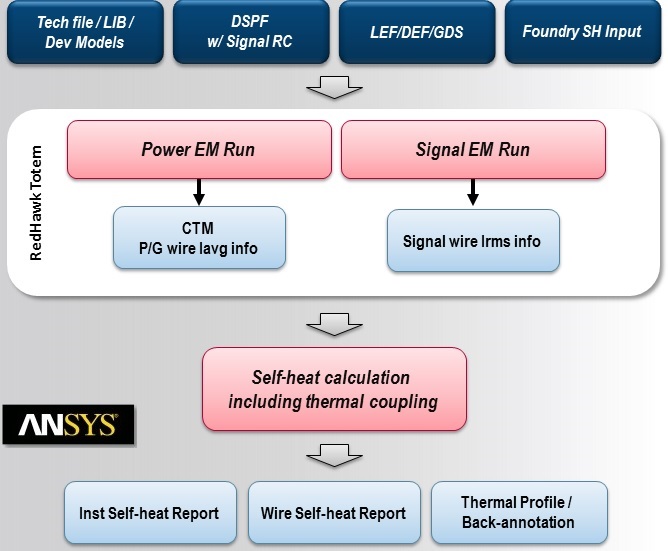
ANSYS self-heat flow using RedHawk and Totem calculates self-heat as well as thermal coupling for instances and wires including thermal profile by taking primary input from design layout (LEF/DEF, GDS), techfile, library and device models, DSPF and foundry input. The Power EM run provides CTM (Chip Thermal Model) and average current information for power/ground wires and the Signal EM run provides rms current information for signal wires which are used in the computation of self-heating and thermal coupling.
Similarly chip thermal interaction on 3D-IC is analyzed by using various other techniques such as FE (Finite Element) modeling of complex 3D-IC structure.
Read Fast & Accurate Thermal Analysis of 3D-ICs for more information.
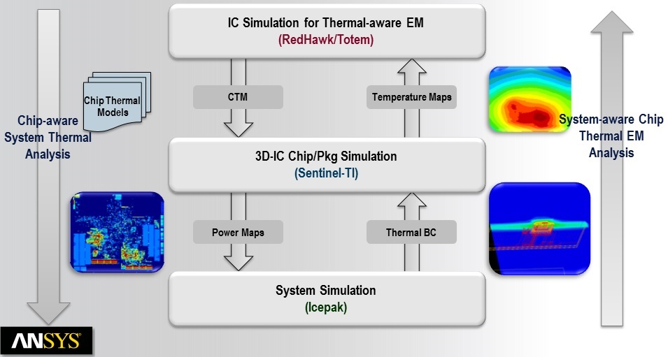
The complete Chip-Package-System solution for thermal analysis is summarized in the above picture where chip-aware system thermal analysis as well as system-aware chip thermal EM analysis can be performed.
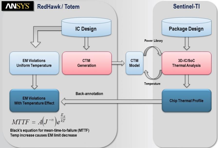
The on-chip thermal-aware EM flow is depicted in the above picture where Sentinel-TI generates the chip thermal profile from the CTM generated by RedHawk and Totem and back-annotates it to EM violations. The MTTF (Mean Time to Failure) can be computed from the available data.
The set of class tools provided by ANSYS are well knit into system-aware-chip and chip-aware-system flows that provide fast and accurate Power Integrity, EM and Thermal Reliability solutions at advanced nodes. Considering extremely low noise and EM margins at these nodes, such solutions at high accuracy levels are must.
More Articles by Pawan Fangaria…..
Share this post via:


Comments
There are no comments yet.
You must register or log in to view/post comments.