Several years ago a former EDA co-worker went to work for MathWorks, so I started paying a lot more attention to this privately held company that is well known for the MATLAB language and analysis environment. Engineers at MathWorks have created a graphical environment called Simulink for both simulation and model-based design of multi-domain dynamic and embedded systems. On the electronics side of product development you can model and simulate analog sensors and circuits at the component level using the PSpice simulator. What about modeling and simulating with both MATLAB and PSpice at the same time, instead of separately? Before this week, you had to divide and conquer, using these two popular software tools separately and then hoping that your actual system would work after a prototype was built.
What Cadence and MathWorks decided to do was connect these two simulation environments together, using the Simulink technology, and that’s good news for systems designers because you can finally model and simulate your entire system before building any prototype. So here’s how you split up your modeling efforts between the tools:
- MathWorks – mechanical, thermal, hydraulic
- PSpice – electrical

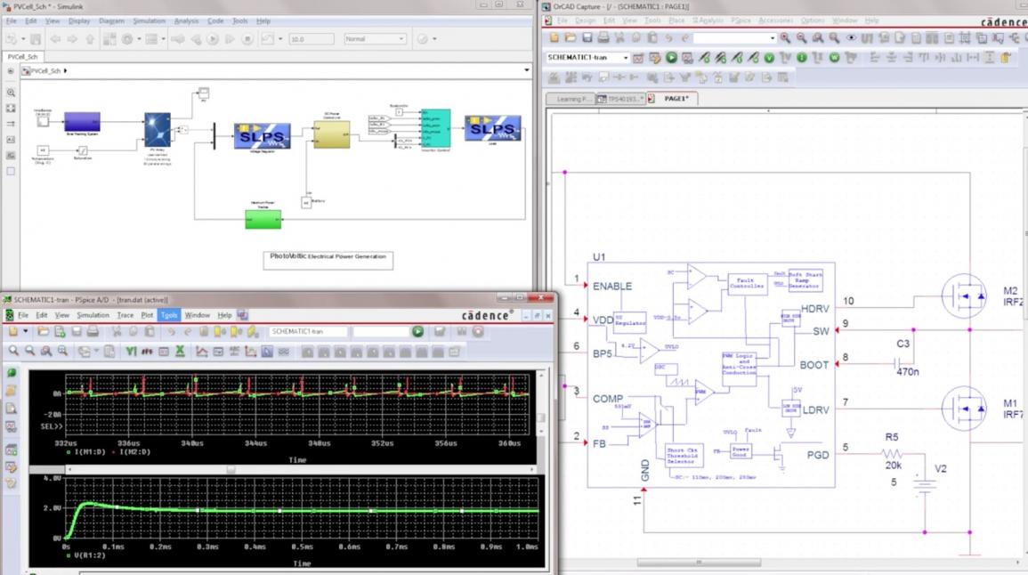
Upper left – Simulink, lower left – PSpice waveforms, right – OrCAD schematics
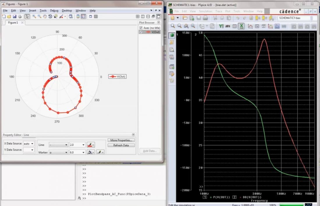
The integration is bi-directional, so you can include PSpice models for analog and AMS in your Simulink (digital models) environment, or place MATLAB models in a PSpice design. You also get to choose which analysis tool to use for visualizing results, it’s really the best of both worlds. Let’s say that you want to visualize a phase plot, then the Simulink window on the left shows you polar plot results while the PSpice window on the right shows you a frequency response:

Polar and Frequency plots
Systems designers doing IoT and automotive projects can quickly benefit from this kind of technology because it shortens the product development cycle and provides feedback and validation that requirements have been met prior to production. The old way of doing product design by building a prototype, testing, iterating and refining are just too slow in comparison to the newer method of modeling a virtual prototype. Applications for this system-level simulation in the automotive market would include[SUP]1[/SUP]:
- Engine control
- Transmission electronics
- Active safety
- Driver assistance
- Passenger comfort
- Infotainment
IoT markets are quite diverse and are characterized by the use of analog sensors and mechanical actuators all controlled by digital electronics[SUP]2[/SUP]:
- Media
- Environmental monitoring
- Infrastructure management
- Energy management
- Medical and healthcare
- Building and home automation
- Transportation
- Metropolitan scale deployments
- Consumer products
Related blog – Eight Improvements for PCB Software
PSpice has been around for decades now and has some 34,000 models ready to be simulated for your next PCB project. The integration between PSpice and Simulink gives you a single, integrated environment for system design and debug. Using the PSpice Device Model Interface (DMI) you can model using C, C++, SystemC, Verilog ADMS components, or MATLAB software-generated code and then simulate.
Simulation results from PSpice can even be visualized in the MATLAB plotting tool using all of the advanced features. Any trace or DAT file can be exported from PSpice into MATLAB by clicking a drop-down menu choice in PSpice. From PSpice you can even start to use MATLAB functions in any of your measurement expressions or behavioral modeling.
Related blog – Growing Innovation in Modern PCB Design Tools
If this approach of using a virtual prototype for system-level design looks interesting, then consider contacting Cadence and MathWorks to get more info. On the sales side of things you still buy PSpice and OrCAD through Cadence or a channel partner, and Simulink through MathWorks. The team at MathWorks has been integrating with many other companies using Simulink over the years, so this integration with Cadence makes a lot of sense.
References
1 – Wikipedia, Automotive electronics
2 – Wikipedia, Internet of things


Comments
0 Replies to “System-level Design for IoT and Automotive”
You must register or log in to view/post comments.