You are currently viewing SemiWiki as a guest which gives you limited access to the site. To view blog comments and experience other SemiWiki features you must be a registered member. Registration is fast, simple, and absolutely free so please, join our community today!
Ann Kelleher is Intel’s Executive Vice President, General Manager, Technology Development, and she gave the first plenary talk to kick off the 2022 IEDM, “Celebrating 75 Years of the Transistor A Look at the Evolution of Moore’s Law Innovation”. I am generally not a fan of plenary talks because I think they are often too broad and general without any real information, but I thought this was a good talk.
She started with the messages that Moore’s law is critical to addressing the needs of computing, that System Technology Co-Optimization (STCO) is the next major evolution of Moore’s law and that there are many challenges to overcome.
She went on to review some of the innovations in device structures and all the products they have enabled.
In her view Moore’s law has gone through four evolutions:
Evolution 1 – geometric scaling. This was the classic Denard scaling era when a geometric shrink of a transistor improved power, performance, and area.
Evolution 2 – as scaling of certain elements of a transistor began to reach limits, novel materials and device structures were introduced to continue scaling. This was innovations like strain and HKMG, and the transition to FinFETs.
Evolution 3 – Design Technology Co-Optimization – co-optimization of the device design and process. For example, shrinking cell height requires fin depopulation and that reduces performance unless the process is improved to compensate. The last several years have seen DTCO becoming increasingly important.
Evolution 4 – System Technology Co-Optimization – just optimizing the device is no longer enough and we need to optimize the entire system!
She gave an example of STCO where chiplets, IP design and validation are DTCO with process technology, and are combined with package, chiplet design and validation integrated with packaging technology, along with software and hardware architecture and validation, to produce an optimized system.
A device includes process technology, transistor & interconnect and foundational IP.
DTCO adds core & accelerator IP and chiplets.
STCO further adds advanced packaging, system architecture, software and applications and workload.
There are many opportunities for innovation:
People – highlighted as the most important, people are the drivers of innovation.
Figure 1 illustrates that Intel continues to be on track to meet their silicon roadmap. I was skeptical Intel could meet the original Intel accelerated timeline, then they pulled it in (18A moved from 2025 to the second half of 2024), and so far, they are meeting it. I am very impressed that Ann and her team are executing at such a high level after a decade of delays at Intel.
On the packaging front Intel is working on Foveros Direct for the second half of 2023, with a 10x higher bump density versus the current Foveros process, alongside higher bandwidth, lower latency, lower power and smaller die area. Intel is also working on pluggable optical interconnect.
Longer term Intel research is working on:
Enabling seamless integration of chiplets with an additional 10x improvement in density and placement flexibility.
Super thin materials to further scale beyond RibbonFET by implementing 2D materials (this is a hot topic at the conference with multiple papers from Intel, TSMC and others).
New possibilities in energy efficiency with more energy efficient memory such as FeRAM (another hot topic), magento electric devices and GaN on silicon.
In summary Ann Kelleher presented a fascinating view of the opportunities and challenges to continue Moore’s law for another decade or more. Intel is clearly back as a leading technology innovator.
Register management tools have been used mostly in a bottom-up approach. There are some documents and/or spreadsheets created by the System Architects that are delivered to the design and verification teams. They then start capturing the HW/SW interface of the peripheral IPs in their in-house or commercial register management tool working their way up to the full SoC.
Using these tools make sure that the different teams are in sync and that there is a single source of truth for the HW/SW interface. This is a great step forward from where different teams were manually maintaining their view of the SoC registers. Jade Design Automation thinks that this could be taken to the next level and register management tools can be used in a top-down approach as well, right from the moment when the first draft of the SoC is created by the System Architect.
How cross domain knowledge can help create better SoCs?
This webinar shows how we can combine tools and practices from seemingly far away domains and how simple ideas can have great impact.
As the System Architect starts capturing the system level memory map and the high level HW/SW interface of the SoC, the Tech Leads need to review the proposed changes, assess the impact on their domains and raise potential issues as early as possible.
The solution proposed in this webinar came from the Embedded SW team, from the other end of the flow. Using a code review tool and process on the design data enables the Tech Leads to review changes before they go live and creates a track record of these reviews. As long as the design data format is human readable (for visual diff) and machine parsable (to auto-generate collateral) this flow can be used on any design aspect with any toolchain.
Learn more about how code review tools and practices can help with the collaboration between the System Architect and the Tech Leads from Tamas Olaszi, Director at Jade Design Automation. Join a live discussion with him on Tue, Dec 13, 2022 10:00 AM – 11:00 AM PST. The concept will be reviewed from the HW/SW interface’s perspective but the same principles can be applied to other aspects of the design flow as well.
Jade Design Automation has a laser sharp focus on register management with a mission to address the register management challenges from system architecture to SW bring-up.
With a good understanding of the challenges that system architects, design and verification engineers, SW teams and technical writers face during complex SoC projects the company offers a tool that mixes the flexibility of the in-house solutions with the robustness of a commercial product.
With an uncompromising attention to quality, state-of-the-art technology and best in class support we can address change requests with a turnaround time that is comparable to the in-house solution.
The company was founded in 2019 by Tamas Olaszi, a long timer of the semiconductor industry. He spent a decade with an Irish EDA company that was offering a tool suite around register management and SoC integration while he lived and worked in Asia, the US and multiple countries across Europe.
After joining Arm in 2014 he worked with his team on internal register management solutions for IoT subsystems and system IP. From this he moved on to building up and managing an embedded SW team that was responsible for the SW bring-up of IoT test boards.
Having seen how difficult it is to maintain in-house solutions for a long period of time and how existing solutions are built on decade old technologies with decade old data models that are inadequate for today’s challenges he decided to start Jade Design Automation with the help of a few co-workers he previously worked together at Arm .
Jade Design Automation is registered and regulated in the European Union.
Successful ASIC providers offer top-notch infrastructure and methodologies that can accommodate varied demands from a multitude of customers. Such ASIC providers also need access to best-in-class IP portfolio, advanced packaging and test capabilities, and heterogeneous chiplet integration capability among other things. Of course, to deliver the above in a viable fashion, the provider needs to pick a focus in terms of what markets it serves. Alchip chose the high-performance markets for its dedicated focus many years ago and has stayed the course. As of last year, more than 80% of its $372M revenue was derived from high performance computing (HPC) related markets.
Prior posts on SemiWiki have spotlighted many of Alchip’s capabilities and accomplishments. Here is one of the latest achievements by Alchip for which it collaborated with Synopsys. Alchip delivered a TSMC 7nm process-based SoC capable of 2.5GHz performance, consuming less than 400 watts of dynamic power on a 480 sq.mm die. Such a performance, power, area (PPA) metric on an AI-enabled data center SoC is noteworthy, with particular attention to be paid to the 400 watts power number.
AI-enabled Data Center SoC
A high-level block diagram of the Alchip implemented SoC (see below) showcases the complexity and highlights the need for a collaborative, multi-company effort.
Of course, for the above SoC which is data center oriented, memory and I/O operations consume an even higher percentage of the total chip power consumption.
With HPC data centers handling increasingly large data sets, memory and other high-speed I/O operations reach extreme levels, leading to elevated thermal conditions inside the server rooms. In addition to the cooling mechanisms deployed within server rooms, lower thermal dissipation from data center chips will go a long way in keeping thermal levels under control. 400 watts of power dissipation is a pretty aggressive target for a data center chip, which in turn calls for aggressively reducing the power consumed by memory and other I/Os.
Alchip-Synopsys Collaboration
A number of members of the TSMC Open Innovation Platform (OIP) teamed up on the AI-Enabled Data Center SoC project, with Synopsys EDA tools, foundation IP and interface IP bringing a lot to bear.
Synopsys offers the broadest portfolio of IP across TSMC technology nodes ranging from 180nm to 3nm FinFET through its continuous innovation cycle for optimizing SoC PPA. Alchip leveraged Synopsys IP portfolio including its optimized cell set tailored for HPC market applications. Included with the IP set are memory design for testability (DFT) and power management support.
Standby Power
Synopsys memory compilers are optimized for power hungry applications: memory standby power is reduced by up to 50% in light sleep mode, by up to 70% in deep sleep mode and by up to 95% in shut down mode.
Switching Power
Clock power is a significant component of a chip’s total power. Through a fully automated multibit-mapping flow from the RTL stage, Synopsys was able to reduce clock power by more than 30%, resulting in more than 19% reduction of the total power. The optimization techniques involved mapping sequential multibits to combinational multibits through De-Banking and Re-Banking.
Optimized Cell Set
Low active power versions of the combinational cells helped reduce dynamic power significantly. Special wide muxes, compressors and adders helped minimize routing congestion and total power. Fast adders help ensured performance was met post route.
PPA Benefits
In addition to reducing power, multibit combinational cells also reduced area. The logic restructuring done as part of optimization techniques reduced congestion to achieve better timing. Flops optimized for Setup/Hold enabled faster timing closure.
Summary
Alchip met its cloud-infrastructure customer’s PPA challenge through its tight collaboration with Synopsys. For Alchip’s press release on this, visit here. With the TSMC N7 based SoC success under its belt, the partners are working together on TSMC N5 and TSMC N3 engagements. For more details contact Alchip.
I am delighted to share my technical insights into RISC-V in this article to inspire and prepare the next generation of chip designers for the future of the open era of computing. If you understand how we build complex electronic devices like desktops and smartphones using processors, you would be more interested in learning and exploring the Instruction Set Architectures.
Usually, we prefer Complex Instruction Set Computer, CISC for desktops/laptops, and Reduced Instruction Set Computer, RISC for smartphones. The OEMs like Dell and Apple have been using x86 CISC processor for their laptops. Let me explain here the laptop design approach. The motherboard has a multicore CISC processor as the main component, which is connected to GPUs, RAM, storage memory, and other subsystems and I/O interfaces. The operating system runs multiple applications in parallel on the multicore processor, managing the memory allocation and I/O operations.
This is how we can realize any electronic system using a processor. However, we prefer System-On-a-Chip using RISC processor for smartphones as it helps us reduce the motherboard’s size and power consumption. Almost the entire system with multi-core RISC CPUs, GPUs, DSPs, Wireless and interface subsystems, SRAMs, Flash memories, and IPs is implemented on an SoC. The OEM Apple is following this smartphone’s SoC design approach even for their MAC books as an OEM trendsetter. All the latest MAC books use their M-series SoCs that use ARM’s RISC processor.
So, it’s evident that the proprietary ISAs Intel’s x86 or ARM’s RISC processors have been the choice of OEMs like Apple, Dell, Samsung, and others, but now why do we need an open ISA like RISC-V beyond all these well-proven proprietary ISAs.
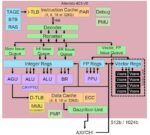
In today’s situation, everyone uses SoCs for their laptops and smartphones. This kind of complex SoC demands both general-purpose and specialized processors. To realize chips like Apple’s M-series SoCs, we need different kinds of processors like RISC CPUs, GPUs, DSPs, Security Processors, Image processors, Machine Learning accelerators, Security and Neural engines, based on various general purpose and specialized ISAs from multiple IP vendors, as shown in figure1.
Figure1: Apple M1 SoC Ref: AnandTech
In this scenario, the major challenges would be:
Choosing and working with multiple IP vendors
Different IP vendors may have different IP licensing schemes, and the engineers will not have the freedom to customize the ISAs and design as they prefer to meet their design goals.
All specialized ISAs will not last/survive for long, affecting the long-term product support plans and roadmaps.
Also, the software/application development and updates involving multiple ISAs and toolchains would be challenging.
RISC-V is a general-purpose license-free open ISA with multiple extensions. It is an ISA separated into a small base integer ISA, usable as a base for customized accelerators and optional standard extensions to support general-purpose software development.
You can add your own extensions to realize your specialized processor or customize the base ISA if needed because it’s open. No license restrictions. So, in the future, we could create all general-purpose and specialized processors using only one RISC-V ISA and realize any complex SoC.
1. What’s RISC-V, and how it’s different from other ISAs?
RISC-V is a fifth major ISA design from UC Berkeley. It’s an open ISA maintained by a non-profit organization, RISC-V international, that involves all the stakeholders’ community to implement and maintain the ISA specifications, Golden reference models, and compliance test suites.
RISC-V is not a CPU implementation. It is an open ISA for both general-purpose and specialized processors. A completely open ISA that is freely available to academia and industry
RISC-V ISA is separated into a small base integer ISA, usable by itself as a base for customized accelerators or educational purposes, and optional standard extensions to support general-purpose software development
RISC-V supports both 32-bit and 64-bit address space variants for applications, operating system kernels, and hardware implementations. So, it is suitable for all computing systems, from embedded microcontrollers to cloud servers, as mentioned below.
Simple embedded microcontrollers
Secure embedded systems that run RTOS
Desktops/Laptops/Smartphones that run operating systems
Cloud Servers that run multiple operating systems
2. RISC-V Base ISA
RISC-V is a family of related ISAs: RV32I, RV32E, RV64I, RV128I
What RV32I/ RV32E/ RV64I/RV128I means:
RV – RISC-V
32/64/128 – Defines the Register width[XLEN] and address space
I – Integer Base ISA
32 Registers for all base ISAs
E – Embedded: Base ISA with only 16 registers
2.1 RISC-V Registers:
All the base ISAs have 32 registers as shown in the figure2, except RV32E. Only RV32E base ISA has only 16 Registers for simple embedded microcontrollers, but the register width is still 32 bits.
The register X0 is hardwired to zero. The special register called Program Counter holds the address of current instruction to be fetched from the memory.
As shown in figure-2, RISC-V Application Binary Interface, ABI defines standard functions for registers. The software development tools usually use ABI names for simplicity and consistency. As per the ABI, additional registers are dedicated for saved registers, function arguments and temporaries in the range X0 to X15, mainly for RV32E base ISA which needs only the top 16 registers for realising simple embedded microcontrollers. But the RV32I base ISA will have all 32 registers X0 to X31.
Figure2: RISC-V Registers and ABI Names Ref: RISC-V Specification
2.2 RISC-V Memory:
A RISC-V hart [Hardware Thread / Core] has a single byte-addressable address space of 2^XLEN bytes for all memory accesses. XLEN to refer to the width of an integer register in bits: 32/64/128.
Word of memory is defined as 32 bits (4 bytes). Correspondingly, a halfword is 16 bits (2 bytes), a doubleword is 64 bits (8 bytes), and a quadword is 128 bits (16 bytes).
The memory address space is circular, so that the byte at address 2^XLEN −1 is adjacent to the byte at address zero. Accordingly, memory address computations done by the hardware ignore overflow and instead wrap around modulo 2^XLEN.
RISC-V base ISAs have either little-endian or big-endian memory systems, with the privileged architecture further defining big-endian operation. Instructions are stored in memory as a sequence of 16-bit little-endian parcels, regardless of memory system endianness.
2.3 RISC-V Load-Store Architecture
You can visualize the RISC-V load-store architecture that is based on RISC-V registers and memory, as shown below in figure3.
The RISC-V processor fetches/loads the instruction from main memory based on the address in PC, decodes the 32-bits instruction, and then the ALU performs Arithmetic/Logic/Memory-RW operations. The results of ALU would be stored back into its registers or memory.
Figure3: RISC-V Load-Store Architecture
2.4 RISC-V RV32 I Base ISA:
RV32I base ISA has only 40 Unique Instructions, but a simple hardware implementation needs only 38 instructions. The RV32I instructions can be classified as:
Here I would like to explain how RISC-V ISA enables us to realize an optimized Register Transfer Level design to meet the low-power and high-performance goals.
As shown in figure4, the RISC-V ISA keeps the source (rs1 and rs2) and destination (rd) registers at the same position in all formats to simplify decoding.
Immediates are always sign-extended, and are generally packed towards the leftmost available bits in the instruction and have been allocated to reduce hardware complexity. In particular,
the sign bit for all immediates is always in bit 31 of the instruction to speed sign-extension circuitry.
Sign-extension is one of the most critical operations on immediates (particularly for XLEN>32),
and in RISC-V the sign bit for all immediates is always held in bit 31 of the instruction to allow
sign-extension to proceed in parallel with instruction decoding.
To speed up decoding, the base RISC-V ISA puts the most important fields in the same place in every instruction. As you can see in the instruction formats table,
The major opcode is always in bits 0-6.
The destination register, when present, is always in bits 7-11.
The first source register, when present, is always in bits 15-19.
The second source register, when present, is always in bits 20-24.
But why are the immediate bits shuffled? Think about the physical circuit which decodes the immediate field. Since it’s a hardware implementation, the bits will be decoded in parallel; each bit in the output immediate will have a multiplexer to select which input bit it comes from. The bigger the multiplexer, the costlier and slower it is.
It’s also interesting to note that only the major opcode (bits 0-6) is needed to know how to decode the immediate, so immediate decoding can be done in parallel with decoding the rest of the instruction.
2.6 RV32I Base ISA Instructions
3. RISC-V ISA Extensions
All the RISC-V ISA extensions are listed out here:
Figure 5: RISC-V ISA Extensions
We follow the naming convention for RISC-V processors as explained below:
RISC-V Processors: RV32I, RV32IMAC, RV64GC
RV32I: Integer Base ISA implementation
RV32IMAC: Integer Base ISA + Extensions: [Multiply + Atomic + Compressed]
RV64GC: 64bit IMAFDC [G-General Purpose: IMAFD]
Integer 64 bits Base ISA + Extensions: [Multiply + Atomic + SP Floating + DP Floating + Compressed]
4. RISC-V Privileged Architecture
RISC-V privileged architecture covers all aspects of RISCV systems beyond the unprivileged ISA which I have explained so far. Privileged architecture includes privileged instructions as well as additional functionality required for running operating systems and attaching external devices.
As per the RISC-V privileged specification, we can realize different kinds of systems from simple embedded controllers to complex cloud servers, as explained below.
Application Execution Environment – AEE: “Bare metal” hardware platforms where harts are directly implemented by physical processor threads and instructions have full access to the physical address space. The hardware platform defines an execution environment that begins at power-on reset. Example: Simple and secure embedded microcontrollers
Supervisor Execution Environment – SEE: RISC-V operating systems that provide multiple user-level execution environments by multiplexing user-level harts onto available physical processor threads and by controlling access to memory via virtual memory.
Example: Systems like Desktops running Unix-like operating systems
Hypervisor Execution Environment – HEE: RISC-V hypervisors that provide multiple supervisor-level execution environments for guest operating systems.
Example: Cloud Servers running multiple guest operating systems
Also, the RISC-V privileged specification defines various Control and Status Registers [CSR] to implement various features like interrupts, debugging, and memory management facilities for any system. You may want to refer to the specification to explore more.
As explained in this article, we could efficiently realize any system, from simple IoT devices to complex smartphones and cloud servers, using a common open RISC-V ISA. With monolithic semiconductor scaling failing, specialization is the only way to increase computational performance. The open RISC-V ISA is modular and supports custom instructions making it ideal for creating a wide range of specialized processors and accelerators.
As we witnessed great success in chip verification from the emergence of IEEE standard Universal Verification Methodology, the open RISC-V ISA will also emerge as an industry-standard ISA by inheriting all good features from various proprietary ISAs and lead us to the future of an open era of computing. Are you ready with RISC-V expertise for this amazing future?
Author: P R Sivakumar, Founder and CEO, Maven Silicon
The Interface IP market has grown with 21% CAGR from 2017 to 2021 and we review the part of this market restricted to the high-end of PCIe, DDR, Ethernet and D2D IP made of PHY and controller targeting the most advanced technology nodes and latest protocol release. We will show that an IP vendor focusing investment on the high-end interconnect IP can benefit for a very healthy ROI based on a business growing with 75% CAGR for 2022 to 2026.
To keep a leading market share on this very demanding IP business, he will have to show the best time to market (TTM) and demonstrate 100% perfect execution. Taking Alphawave as an example, If the company can perfectly execute this strategy, he can grow his IP business from $90 million in 2021 to $600 million or more in 2026.
We have used market information extracted from the “Interface IP Survey & Forecast”, and we have selected the following interconnect protocols and the best technology nodes to focus on, because showing the highest ROI, 7nm, 5nm, 3nm and even lower:
PCIe 4 and above (PCIe 5, 6…)
CXL 1, CXL 2, CXL 3
UCIe
Ethernet based on 56G SerDes, 112G SerDes, 224G…
LPDDR5 memory controller
HBM3 memory controller
We can see that all these protocols support HPC, becoming the segment leader (size and growth) for TSMC in 2022.
Revenue and Growth Rate by Platform – TSMC 2022
Selected Protocol Forecast 2022-2026
IP outsourcing rate and IP market size are growing year over year (about by 20% by year for the total interface IP market since the last five years) and, as we will see, even more for the high-end protocol-based IP.
For PCIe 5 and 6, mature technology nodes don’t make sense and we split the PHY IP forecast between mainstream and advanced technology nodes, as ASP are different, but the Controller IP ASP is expected to be technology independent. We assume that a combo PCIe/CXL PHY will be proposed.
Advanced memory controller includes:
DDR5, LPDDR5 memory controller according with above technology split
GDDR6, GDDR7 targeting 7nm, 5nm and below
HBM3 targeting 7nm, 5nm and below
The picture below describes the number of VHS SerDes IP commercial design starts for the three data rate: 56Gbps, 112Gbs and 224Gbps for the next 5 years.
SerDes PHY IP Number of Sales Forecast 2021-2026
The semiconductor industry is undertaking a major strategy shift towards multi-die systems.
Multi-die systems are driving the need for standardized die-to-die interconnects. Several industry alliances have come together to define such standards, the most promising being Unified Chiplet Interconnect Express (UCIe).
D2D Design Start IP Forecast 2021-2026
Top4 High-End Interface IP by Revenue 2021-2026
The group made of the top 4 Interface IP (PCIe, DDR, Ethernet and D2D) is forecasted to grow with 27% CAGR for 2022 to 2026. If we consider the high-end only, the Global CAGR for HE Top 4 Interfaces will be 75% for 2021 to 2026:
The Top 4 Interface IP by Revenue 2021-2026
The weight of the HE Top 4 protocols IP was $370 million in 2021, the value forecasted in 2026 will be $2115 million, or CAGR of 75%, compared with 27% for the overall IP sales for these Top 4 protocols IP.
We will look at Alphawave IP vendor case study. Created in 2017, the company has focused on high-end IP since the beginning with PAM 4 DSP based 112G SerDes, supporting Ethernet and PCIe segments. The strategy was successful as 2021 IP revenues was $89.9 million. In the meantime, Alphawave IP has acquired an Ethernet controller IP vendor and propose PCIe controller validated by the PCI-SIG for PCIe 5 complete solution.
Moreover, in June 2022, they acquired OpenFive. The first result was to enlarge Alphawave IP portfolio and address two more segments: high-end DDR memory controller (HBM3 and LPDDR5) and D2D. The second result was to bring design services capability to create a potential emerging chiplet business.
That’s why Alphawave is a good candidate for a case study “What can be the potential business development for an IP vendor focusing primarily on high-end Interface IP (PCIe, DDR memory controller, Ethernet and D2D)”.
2022-2026 Market Share Evolution When Focusing on
High-End Interface IP
Starting with 24% market share of HE Interface ($370 million in 2021), we evaluate the revenues generated when keeping deploying this strategy, with three scenarios: flat market share, growing by 1% per year and by 10% by year. The real case may be inserted between these two scenarios, calling for Alphawave revenues from IP only on HE interfaces market to be between $500 million and $800 million in 2026.
In 2020, we have seen the emergence of Alphawave IP building strong position on the high-end interface IP segment (thanks to PAM4 DSP SerDes), creating “Stop-for-Top” strategy, by opposition with Synopsys “One-Stop-Shop”. If we consider that this high-end segment, strongly driven by HPC (including datacenter, IA, storage, etc.), is expected to considerably grow on the 2020 decade, Alphawave IP could enjoy major market share on this $2 billion interface IP sub-segment by 2026, a revenue between $500 and $800 million being realistic.
** This white paper has been sponsored by Alphawave IP, nevertheless the content reflects the author’s positioning about the IP market and the way it expected to evolve in the future, during the 2020 decade.
Extreme ultraviolet (EUV) lithography targets patterning pitches below 50 nm, which is beyond the resolution of an immersion lithography system without multiple patterning. In the process of exposing smaller pitches, stochastic patterning effects, i.e., random local pattern errors from unwanted resist removal or lack of exposure, have been uncovered due to the smaller effective pixel size and the smaller number of photons absorbed per pixel. In this article, I present a way to visualize the defective pixel rate and how it may be tied to stochastic defect density.
Here, for the most straightforward analysis we will consider an idealized image: a 1:1 duty cycle line grating, with binary amplitude. Also, we will focus on the pitch range of 50 nm and below for a 0.33 NA EUV system. Consequently, the normalized image can be represented mathematically as 0.25+(1/pi)^2+1/pi*cos(2*pi*x/pitch). The absorbed dose profile in the resist will therefore be proportional to this expression, basically multiplied by the absorbed average dose. Again, for keeping things simple, we ignore the polarization and angle-based 3D-mask effects which are actually present, as well as electron blur, which would become much more significant for the 0.55 NA EUV systems [1].
This absorbed dose profile is plotted on a preset grid. I used a 99 x 101 nm pixel grid, where the pixel is normalized to 1/100th of the pitch. Poisson statistics is used to obtain the random absorbed dose at each pixel. The pixel is considered defective if it falls below a certain threshold for exposure, producing an unexposed defect, or if it exceeds the same threshold, producing a potential bridge defect. By changing the dose, improperly unexposed or exposed pixels can be visualized (Figure 1).
Figure 1. Stochastic defects at lower doses (left) tend to be unexposed pixels (blue in central orange area), while at higher doses (right) tend to be improperly exposed pixels (orange in top/bottom blue area).
By scanning the dose, the defective pixel rate may be plotted as a function of absorbed dose. Unexposed pixels decrease with increasing dose, while beyond some dose, improperly exposed pixels leading to bridging start increasing (Figures 2,3). The smallest defective pixel rate that can be detected for this small grid is 1e-4. The defective pixel rate is not a direct measure of predicted defect density. Instead, we rely on a formula from de Bisschop [2] used for inspection image pixels: defects/cm2 = 1e14 pixNOK/(NPR), where pixNOK is the defective pixel rate, N is the average number of pixels per defect, P is the pitch, and R is the pixel size in nm. For the 50 nm pitch case, a 3e-10 defective pixel rate with 0.5 nm/pixel and 100 pixels/defect gives 12 defects/cm2. For the 40 nm pitch case, a 1e-9 defective pixel rate with 0.4 nm/pixel and 125 pixels/defect gives 50 defects/cm2. These values are comparable to recently published values [3].
Figure 2. Defective pixel rate (out of 99 x 101 0.5 nm pixels) for 25 nm half-pitch vs. absorbed dose.
Figure 3. Defective pixel rate (out of 99 x 101 0.4 nm pixels) for 20 nm half-pitch vs. absorbed dose. Optimum absorbed dose and minimum defective rate are higher for the reduced pitch.
At the same average absorbed dose, the smaller pitch shows larger variations due to the smaller pixel size. It is therefore to be expected that larger doses are preferred to maintain a given defective pixel rate. The standard deviation is also smaller for the smaller pitch (due to fewer photons within the grid area), within a given dose range, which would also lead to a higher minimum defect rate.
The immensely greater photon density of ArF immersion systems has allowed them to avoid seeing stochastic effects down to the 80 nm pitch (Figure 4), even with relatively low absorbed mJ/cm2.
Figure 4. Negligible stochastic effects show at 80 nm pitch for ArF immersion lithography, even with only 3 mJ/cm2 absorbed.
References
[1] T. Allenet et al., “EUV resist screening update: progress towards High-NA lithography,” Proc. SPIE 12055, 120550F (2022).
[2] P. de Bisschop, “Stochastic printing failures in extreme ultraviolet lithography,” J. Microlith/Nanolith. MEMS MOEMS 17, 041011 (2018).
[3] S. Kang et al., “Massive e-beam metrology and inspection for analysis of EUV stochastic defect,” Proc. SPIE 11611, 1161129 (2021).
Dan is joined by Hassan Triqui who has over 20 years of experience in the technology sector. Prior to spearheading Secure-IC’s development into a major player in embedded cybersecurity solutions, Hassan was a former senior executive at Thales (Talles) and Thomson.
Dan explores Secure-IC’s vision and strategy to deploy integrated cybersecurity capability across many products and markets. The Company’s chip to cloud vision is discussed as well as its recent acquisition of Silex Insight. The impact of the complete portfolio is examined.
The views, thoughts, and opinions expressed in these podcasts belong solely to the speaker, and not to the speaker’s employer, organization, committee or any other group or individual.
After attending the TSMC and Samsung foundry conferences I wanted to share some quick opinions about the foundry business. Nothing earth shattering but interesting just the same. Both conferences were well attended. If we are not back to the pre pandemic numbers we are very close to it.
TSMC and Samsung both acknowledged that there could be a correction in the first half of 2023 but over the next 5 years semiconductors and the foundry business will see very healthy growth rates. Very good news and I agree completely. The strength and criticality of semiconductors has never been more defined and the foundry ecosystem has never been stronger, absolutely.
At their recent Foundry Forum Samsung forecasted (citing Gartner) that by 2027 the semiconductor industry will approach $800B at a 9% Compound Annual Growth Rate and the foundry industry will experience a 12% CAGR. Samsung Foundry predicts advanced nodes (< 7nm) to outgrow the foundry industry at a 21% CAGR over the next five years and predicts its business will grow to approximately $26B by 2027 with a 20% CAGR.
It will be interesting to see what TSMC guides for 2023 during the Q4 2022 earnings call. Any guesses? Double digits (10-20%) growth is my guess. N3 will be in full production and it will be the biggest node in the history of TSMC, my opinion.
According to the World Semiconductor Trade Statistics (WSTS) the semiconductor industry is now expected to grow 4% in 2022 and drop 4% in 2023. After a 26% gain in 2021 this should not be a surprise. TSMC still expects 35% growth in 2022 and based on their monthly numbers that sounds reasonable.
For Samsung the FinFET era has come to an end with the R&D focus being on GAA. Samsung had a good run at 14nm even getting a piece of the Apple iPhone 6s business. And let’s not forget that Globalfoundries licensed Samsung 14nm so that success belongs to Samsung as well as GF.
Unfortunately, Samsung 10nm was an utter failure in both yield and PPAC (performance, power, area, cost). TSMC 10nm did not fair well either with the exception of Apple. The ROI between 14/16nm and 10nm just was not enough for most customers and the promise of 7nm was worth the wait.
7nm did much better and Samsung again came back to the competitive table. Samsung 14nm was still a stronger node but 8/7nm is doing very well. This can be seen with the current TSMC 7nm slump as Samsung is a cheaper alternative. Unfortunately, Samsung 5/4nm had serious PDK and yield problems so the lion’s share of the leading edge FinFET market went back to TSMC and will stay there, my opinion.
This leaves the door wide open for Intel Foundry Services to get back in the foundry game. IFS will be spending time with us at IEDM this coming week so we can talk more after that. If Intel executes on their process roadmap down to 18A this could get really interesting.
All three foundries are talking about GAA and Samsung is even in very limited production at 3nm GAA but personally I think the FinFET era will continue on for a few more years as we get the kinks worked out of GAA. In talking to the ecosystem at the conferences, HVM GAA is still years away and the PPAC (power/performance/area and cost) is still a big question. Based on the papers I have seen we should get a pretty good GAA update next week at IEDM. Scott Jones and I will be there amongst the media masses.
One of the more interesting battles between Samsung and TSMC became clear at the conferences and that is RF. I fully expect IFS to hit this market hard as well. Based on the talk inside the ecosystem, Samsung 8nm RF is a cheaper non EUV version of TSMC N6F and it seems to be experiencing a surge in popularity. TSMC N6F however is set to fill the N7 fabs so we should see a big push from TSMC in that direction. At the recent TSMC OIP analog automation, optimization, and migration were popular topics( TSMC OIP – Enabling System Innovation , TSMC Expands the OIP Ecosystem! ). But again, RF chips are very price sensitive so if the design specs can be met at Samsung 8RF and the ecosystem is willing then that is where the chips will go, my opinion.
Source: Samsung
Capacity plans were discussed in detail at both conferences. If you look at TSMC, Samsung, and Intel fab plans you will wonder how they will be filled. TSMC builds fabs based on customer demand which now includes pre payments so I have no worries there. Samsung and Intel however seem to be following the Field of Dreams strategy as in “build it and they will come”. I have no worries there either. If all of the fab expansion and build plans that I have seen announced do actually happen we will have oversupply in the next five years which is a good thing for the ecosystem and customers. TSMC, Samsung, and IFS can certainly weather a pricing storm but the 2nd, 3rd, and 4th tier foundries may be in for rougher times.
Just my opinion of course but since I actively work inside the semiconductor ecosystem I am more than just a pretty face.
Current owners of a wide range of Hyundai connected cars encompassing multiple model years are receiving or have received notification of the availability (i.e. eligibility) for a software upgrade that will connect their in-vehicle radio to the Internet. For those owners who receive and have this update installed they may not realize they are experiencing a first-of-its-kind experience – a connected or hybrid radio experience in a mass market vehicle.
Notably, the experience is enabled in the Hyundai Ioniq 5 – an electric vehicle. I write “notably” because we just learned this week that Ford Motor Company’s F-150 Lightning comes with no AM radio. The Hyundai Ioniq 5 proudly preserves AM radio along with Internet access that allows the system to display station ID and logo, streaming promos for the station and its Website, music track and artist, and streaming elements of broadcast advertising.
All of this extra information related to the broadcast is referred to as “metadata” and broadcasters have struggled to deliver the information in a consistent manner – while automakers have struggled to render the information consistently. Working with Xperi, Hyundai is delivering all of it – now – in millions of dashboard systems.
The integration of this metadata – what Xperi calls DTS AutoStage – is only the first step in the transformation of broadcast radio. The availability of the Internet connection and the data ultimately means that future software updates could add content search capability to the radio experience or even alerts and links to further information, Internet content, or e-commerce opportunities.
It was just three years ago that NextRadio gave up on trying to deliver a hybrid radio experience via activated FM chips in Android phones with cellular service from Sprint – now part of T-Mobile. It was a valiant effort and a clever solution leveraging HD Radio technology to create a searchable broadcast solution. The complexity of the NextRadio solution and Apple’s refusal to activate the FM chips in its own phones doomed this ambitious effort.
Audi was next with its own concept of a hybrid radio with a system developed entirely in house and originally deployed only in the most expensive Audi, the A8, and originally only in Europe. Parent Volkswagen has since indicated its plans to bring its hybrid radio platform to all Volkswagen’s brand – and that rollout is steadily proceeding.
The focal point of the Audi hybrid solution – connecting the radio to the Internet – was the ability of the in-car radio to grab a radio station’s Internet stream more or less seamlessly when the terrestrial signal was lost due to a car driving out of range. The idea was as clever as the NextRadio solution, but it was not scalable beyond Volkswagen vehicles and it, too, was and is a bit of a Rube Goldberg proposition with inconsistent execution across platforms.
Mercedes Benz arrived on the hybrid radio scene last year with its own hybrid radio enabled by Xperi’s DTS AutoStage technology. The Mercedes offering added unique HMI elements such as a kind of carousel of radio station logos that made manual searching for a station in a car a truly unique experience and potentially less distracting than turning a knob – though maybe more distracting than pressing a button.
To be clear, Mercedes was first to deploy the DTS AutoStage solution. Hyundai is the first to bring DTS AutoStage to the masses. In fact, Hyundai is simultaneously bringing DTS AutoStage to multiiple Kia and Genesis models as well. Tesla owners may also soon discover their vehicles infused with DTS AutoStage.
The onset of electric vehicles has thrust the in-car experience of radio into the spotlight. Lucid Motors announced this week that its full line-up of vehicles will be equipped with SiriusXM satellite radio technology. The announcement cut through the growing suspicion that emerging EV makers – like Tesla – were somewhat ambivalent about including SiriusXM reception in all their vehicles.
TuneIn has lately been pointing the way to an exclusively Internet-based in-vehicle radio experience. TuneIn recently added Rivian to its existing roster of automotive partners which already includes Tesla, Mercedes, Polestar, and Jaguar Land Rover. TuneIn is also available via Amazon’s Alexa digital assistant wherever it is available in an embedded system.
Mercedes, Hyundai, and Tesla are all pointing the way toward a digital, searchable, delightful embedded radio experience that includes FM AND AM. Hyundai is first to bring the DTS AutoStage hybrid radio technology to the masses, but it won’t be the last.
No doubt that the design success of nowadays system on chips (SoCs) is directly linked to the success of cost control. More market opportunities are open for less expensive system on chips and electronic systems.
Both the design cost prediction and the resource tracking during the design process, are key to such a success
Predicting design cost need to cover all aspects: design (EDA) tools, computing servers, human resources, external IP cores, etc. All these aspects need to be tracked automatically by reporting any problem like a resource that is no longer available and measuring the impact on the subsequent design steps. Otherwise, the financial impact is significant especially in correlation with tight tape-out schedules.
INNOVA Advanced Technologies through its PDM (Project & Design Management) tool is the first software solution in the market which consider all the above aspects, simultaneously and automatically.
INNOVA Advanced Technologies has been founded in 2020 by seasoned from the semiconductor industry. Its solution is intended for designers as well as design managers of complex and multi-domain projects, ranging from microelectronics to computer science. It helps them to manage projects and resources in one unique place.
INNOVA Project and Design Management (PDM) software Platform offers a single portal that links areas that were, until now, considered separately. This includes all management of resources of a complex design project: design flows and tools, computing servers, and also human resources.
Being fully compatible with design and IT systems in place, this disruptive and non-intrusive solution serves as a single portal. It helps reduce the complexity of using design tools and dedicated design environments. Thanks to its rich reports including alarms and dashboards, optimal decisions can be made in terms of design resource planning, monitoring and resource adjustment through a complete design live cycle.
For each design step, traditionally dozens of software tools are required and often several hundred design engineers are involved throughout a project such as designing a communication chip or a microprocessor.
There are also significant intangible resources involved: predesigned blocks, various software and design flows, computer resources (server farms, etc.), and libraries in connection with companies manufacturing electronic components.
PDM as an open and secured platform correlates design projects directly with the involved design resources. The tool is fully customizable and both graphical and script-based APIs are open to the users.
Thanks to the INNOVA PDM Platform, it is possible to consult information related to current projects: progress, rate of occupation of human resources, the anticipation of possible delays, and the effects they may have on the rest of the design chain, etc. This multidimensional tracking of EDA tool licenses, servers either local or cloud-based is real time.
Capitalization on past experiences is made possible through consultation and a deep reporting of past projects. PDM provides a clear prediction (ML-based) & tracking answers the fundamental question of how much design resources I need to start my design project and how may I track real-time design task execution and report any problem. In addition to easy tracking, PDM provides scheduling capabilities to automatically manage design tasks and jobs based on resource availability.
Compared to traditional and ad-hoc internal solutions, INNOVA claims up to 30% cost reduction with PDM in place within a corporation.
A webinar is planned by INNOVA where INNOVA experts will be presenting typical cases of how to reduce the cost of EDA licenses and computing servers and also how to plan the most optimal and cost-effective package of tool licenses for a design project. You can register for this webinar here: Reduce design cost by better managing EDA tool licenses and servers