Often it is considered safer to be pessimistic in estimating IR-drop to maintain power integrity of semiconductor designs; however that leads to the use of extra buffering and routing resources which may not be necessary. In modern high speed, high density SoCs having multiple blocks, memories, analog IPs with different functionalities and IO cells integrated together on the same chip, space is a costly real estate and that must be used carefully. While keeping electromagnetic interference within acceptable limits, it is important that power and signal integrity must be addressed with accuracy for best possible performance and reliability.
So, how do we estimate the actual IR-drop in order to design a right sized power delivery network (PDN) and address these concerns? I was delighted to see this research paperpresented jointly by ST Microelectronicsand Apachein last PATMOS(International Workshop on Power and Timing Modeling, Optimization and Simulation). ST actually evaluated the impact of substrate on IR-drop reduction by extending the standard cell electrical characterization with the substrate characterization and noise analysis capabilities of Apache’s tools RedHawk and CSE (Chip Substrate Extension) and implemented this methodology in designing their complex microcontrollers for automotive applications that has severe area constraints. The methodology for accounting substrate parasitics in the design of PDN has been successfully implemented in ST’s digital design flow.

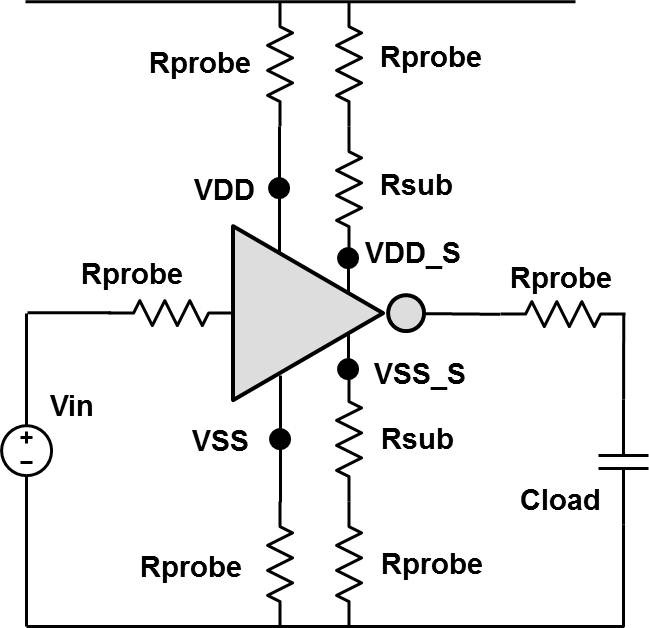
Main sources of current injection into the substrate by the digital core are the simultaneous switching noise (i.e. power supply fluctuation and ground bounce) and capacitive coupling of transistor sources and drains. To model the cell for noise injected into the substrate, the transistor bulk terminals have been separated from the P/G network, and a resistance extracted from the substrate technology parameters representing the path between the well P/G contacts and the transistor bulk has been inserted to probe the noise injected into the substrate network by each transistor. The cell netlist has a dedicated pin to bias the transistor bulk, which can be used to probe the substrate currents. Well resistance must be modeled from the transistor body to the well contacts, and a series resistor has been inserted between the probing pin and the substrate biasing contact of the standard cell.

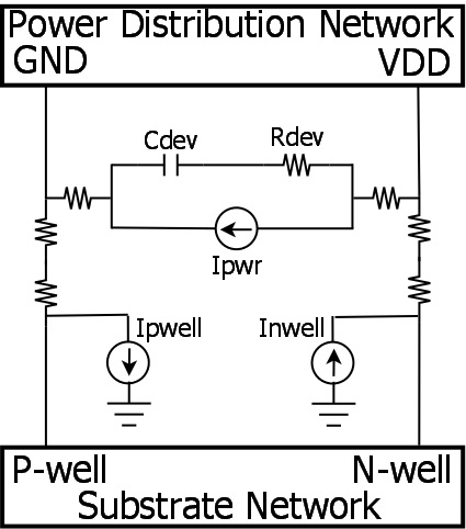
The extended cell macro model includes well resistances and two additional current sources, Ipwell and Inwell that represent the substrate current injection as shown in the figure. The substrate passive network parasitics are represented by a lumped RC mesh.
The IR-drop simulation based on this model is performed by characterizing the library of standard cells and IPs to obtain their current profiles, estimating the power consumption, extracting the RC mesh for the top level PDN and the substrate and performing power integrity analysis.

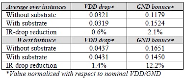
The power integrity analysis done with this approach on ST’s leading edge industrial microcontroller, STXX with embedded Non Volatile Memory (eNVM) and integrated with digital core, analog blocks and IO cells on the same die, shows interesting results. The static IR-drop analysis shows a reduction of voltage drop when the substrate contribution is taken into account.

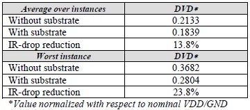
In case of dynamic IR-drop analysis, capacitive coupling between VDD and GND networks due to the decoupling capacitances (intrinsic, extrinsic and substrate parasitic capacitances) is also taken into account. The reduction in dynamic voltage drop (DVD) due to the substrate is more significant than that in static case. This is due to the fact that the substrate contributes significantly in the overall on-chip decoupling capacitance.
Hence, by taking the substrate into account, a more accurate and less pessimistic IR-drop analysis is performed that guides the designers not to add unnecessary extra routing resources and extrinsic decaps on-chip while guaranteeing the power integrity targets. This method through the use of RedHawk and CSE provides more accurate estimations for power integrity as well as saves costly area on the chip. An icing on the cake is that this flow for substrate noise analysis can also be used to explore different technologies such as highly doped vs. lightly doped, with or without deep n-well to improve the power integrity.
This was an interesting paper to study and discover that the substrate can be a blessing in disguise as opposed to its nature of impacting the noise integrity of analog and IO cells. However, in order to make the best use of it, careful modeling of substrate parasitics must be done at the top level PDN. Interested designers can go through the actual paper to study many details and references to know the actual physics behind these models and technology.

More Articles by Pawan Fangaria…..
lang: en_US
Share this post via:


Comments
There are no comments yet.
You must register or log in to view/post comments.