You are currently viewing SemiWiki as a guest which gives you limited access to the site. To view blog comments and experience other SemiWiki features you must be a registered member. Registration is fast, simple, and absolutely free so please, join our community today!
Nonvolatile memory capacity reached 64 Gb levels when NAND Flash half-pitch reached 20 nm [1]. Having reached 14 nm [2], NAND Flash half-pitch is no longer being reduced, now that it has entered the 3D era. However, recently, 3D XPoint has found applications within the Optane platform [3]. The lithography for patterning 20 nm half-pitch lines that make up these memories is another opportunity to look at basic aspects and limitations of currently known lithographic approaches in the industry.
The method for patterning 20 nm half-pitch lines is self-aligned double patterning (SADP). This approach starts with 80 nm pitch lines which actually only serve to support sidewall layers known as spacers (Figure 1). Etching the spacers vertically leaves only the sidewall portions. The original lines are then removed, and the spacers form a 40 nm pitch line pattern.
Figure 1. With SADP (self-aligned double patterning), sidewall spacers define twice as many lines as the starting photoresist.
With SADP, the feature dimension is determined by the spacer width, which, in turn, is controlled by deposition. The lithography does not affect the feature dimension, but an error could produce alternate spacing errors (“pitch walking”); this may be compensated by having the lithography synchronized with subsequent spacer deposition and etching [4].
40 nm line pitch lithography considerations
The 80 nm pitch lines can be formed by immersion lithography using a scanner with 1.35 numerical aperture and 193 nm wavelength [5]. While this resolution is achievable on this tool, the illumination must be restricted (Figure 2). The distance of the illumination source from the center in the y-direction affects the phase difference between the 0th and 1st diffraction orders of the 80 nm pitch, which is also proportional to the defocus distance. Moreover, the polarization should be restricted, for best results [6].
Figure 2. 80 nm pitch with immersion lithography requires very restricted illumination. Excluding the orange portion of the dipole would improve the defocus window.
EUV tools can also achieve 40 nm pitch directly [7], without using SADP. However, the illumination is still restricted to a leaf-shaped dipole region (Figure 3).
Figure 3. 40 nm pitch with EUV lithography is directly impacted by rotation. The labels indicate the range of phase differences between 0th and 1st orders in degrees. The red hollow circles indicate the rotation of the originally targeted source points (edge compared to center). Some are rotated to locations where they can no longer produce any image; others suffer larger defocus effect.
The main difficulty here is the rotation of the EUV illumination (since EUV projection systems must use off-axis mirrors), going from the center of the arc-shaped slit (i.e., the exposure field) to the edge. On the NXE:3400, it amounts to a little over 18 degrees [8]. As shown in Figure 3, at 30 nm defocus, the rotation can expand the phase difference range between the 0th and 1st orders from 30 degrees for the selected source point set, to over 60 degrees. This is to be expected as rotation naturally travels some distance in the y-direction Such a large range will result in a further degraded image, and also photon division into more phase difference bins, leading to worse stochastics [9]. Furthermore, some points are even rotated to where they cannot produce an image anymore, since the 1st order is pushed out of the numerical aperture.
The options for 40 nm line pitch are summarized below:
Crosspoint considerations
The 3D XPoint has a new component, a selector-memory stack on a 40 nm pitch in both x and y. Given that 40 nm pitch lines are patterned by SADP, the patterning of the stack has three options. First, the stacks may be patterned as 2D array, using a 2D SADP approach [10]. Alternatively, the stacks may emerge automatically from two crossed 1D SADP steps, one for x-lines and one for y-lines as shown in this Intel video: [11]. This requires an extra mask, of course. Finally, the stacks may not even be patterned separately. However, this option has some risk for crosspoint stack lower portions merging due to profiles not being straight [12] (Figure 4). This can be avoided of course, if the dielectric between stacks is selected to be etched along with the stacks rather than selected to remain.
Figure 4. After etching for the first direction, dielectric is backfilled before cutting in the other direction. However, with a sloped stack profile, the lower portion of the stack is shielded from cutting by the upper portion of the dielectric.
The crosspoint stack fabrication options are summarized below:
Assuming 3D XPoint uses the X-SADP + Y-SADP option, a two-tier structure would require 7 instances of SADP: Bottom lines, Bottom crosspoint X, Bottom crosspoint Y, Middle lines, Top Crosspoint X, Top Crosspoint Y, Top lines. Going to four tiers, this would increase to 13 (5 sets of lines + 4 SADP pairs for the crosspoint layers in between). However, integrating with the line SADP could presumably use SADP only 5 times to get four tiers.
SADP in 3D NAND
3D NAND also eventually used SADP, due to 20 nm bit line half-pitch [13]. If bit line half-pitch needs to be reduced below 20 nm, self-aligned quadruple patterning (SAQP) could become necessary.
Reuters reports that Uber has quietly launched a service to give public health officials quick access to data on drivers and riders presumed to have come into contact with someone infected with COVID-19. Now Uber, one of the primary vectors spreading the disease with hundreds of thousands of masked drivers worldwide guiding shared rides without passenger-protecting partitions, is going to facilitate contact tracing for health officials worldwide.
This can be seen as Uber being super helpful to public health officials trying to track down exposures. It might reflect Uber’s awareness of its own complicity in the spread of the virus having yet to provide adequate safety measures. Or it can be seen simply as Uber automating – via a Web portal – a process of information sharing which was becoming onerous to support on a one-at-a-time basis. It can also be seen as Uber trying to score points with public officials even as it continues to operate in an unsafe manner.
One can only assume that Uber is on firm legal grounds in sharing this passenger and driver data, but Uber’s privacy policy makes limited mention of data sharing and assures users of complete control. Exactly how a consumer can control access to their personal information on a ride-by-ride basis is unclear.
I am reminded of the virus testing that was offered in my mother’s assisted living facility. All residents and staff were tested, but my mother said she was not given the option of not being tested, nor was she availed of the potential consequences of a positive test – i.e. a relocation to another distant facility.
What if, next time a passenger hails an Uber, he or she is informed that their access to Uber services is subject to data sharing with public health authorities and law enforcement? Should that disclosure appear on the screen before requesting a ride or maybe on a sign in the backseat or on the inside of the window?
By now, millions of Americans have had their temperature and personal information taken before entering a facility, such as a gym or restaurant. Clearly these measures are in place for contact tracing in the event of an infection.
There is no overt disclosure currently being made to users of Uber, Lyft, or any other ride hailing service, which means any such data sharing is taking place under the broad and potentially ambiguous guidelines of an unread privacy statement. If Uber or any other operator is going to share ride information with health officials, a more overt disclosure of these actions – and not just a phone call to Reuters – is in order.
In a time and place where privacy is a precious but deteriorating commodity, it’s time to restore some integrity to the process of controlling our personal information. Uber, above all other operators, ought to be cognizant of the value of privacy and the cost of violating it. In the recent past the has seen multi-million-dollar fines paid and employees fired.
At a time when Uber is operating in an unsafe manner without proper driver and passenger protections, the company can hardly be seen as a paragon of coronavirus mitigation measures. Everything about Uber is unsafe from is business ethos of hacking all norms and convetions to its use of contract workers driving their own or rented cars.
The COVID-19 pandemic has only accentuated the danger of the ride hailing experience by introducing unsafe operating conditions with no in-vehicle physical barrier to viral transmission. Who is Uber to be sharing driver and passenger data? Is Uber going to test its drivers? No. Is Uber going to take the temperature of passengers? No.
According to accounts in “Super Pumped,” there was a time when former CEO Travis Kalanick’s Uber gathered data on passengers long after they had left their Uber rides. Kalanick wanted to see what he could learn about his customers and their behavior beyond the drives. This privacy invasion was detected and terminated – but it was just one of many violations of privacy engaged in by Uber.
The report from Reuters reveals a broader range of ongoing information sharing with U.S. law enforcement officials in emergencies or criminal investigations. Uber, Lyft, and other ride hailing operators have presumably been fielding and processing information requests for assistance for more than a year – leading to the creation of supportive information sharing infrastructures and, now, a COVID-19 targeted portal.
The day can’t be far away when the forward facing cameras in ride hailing vehicles, limousines, and taxis are broadly shared in real time to combat traffic scofflaws and crime or maybe just to forecast the weather. For now, though, let’s just consider this Uber incursion.
An NBC report notes: “In the first half of the year, Uber received a total of some 560 coronavirus-related requests from public health departments in 29 countries, most of which were processed by the company within two hours, company officials said. That compares to only 10 requests from health departments globally in 2019.”
Uber is now offering a portal for public health departments to make data requests based on trip receipts or passenger names. Health officials are prompted to specify what actions they want Uber to take, notes NBC. Uber told NBC that “customers with a confirmed infection are automatically blocked from the platform for at least 14 days.”
I am already envisoining the stricken COVID-19 sufferer getting his or her positive test results and hailing an Uber to get to the hospital – only to be rejected by the platform now that the data sharing has kicked in. Crazy, right?
Contact tracing is an important and essential element to reversing the resurgence of the coronavirus. What is most remarkable about the Uber initiative is that it appears to single out one transportation service provider rather than reflecting a wholistic approach encompassing all transportation resources. Might this lead to a new sort of COVID-free transit credential usable for all modes of transportation?
Uber is a viral vector, so its cooperation in sharing this information makes sense. It is practically an admission of guilt or responsibility for potentially helping to spread the virus. That being said, a more overt disclosure to Uber drivers and passengers regarding this data sharing initiative is essential.
Perhaps even more important, we need a reconception of privacy in a post-COVID-19 world. European countries that embraced contact tracing software from Google have only just come to the realization that the code will capture and share location information with Google. Nothing less than a process of re-educating consumers regarding proper privacy etiquette and hygiene is necessary. With COVID-19 looming the pressure is on to rethink our naive notions of privacy in the context of beating back a pandemic.
KLA reports excellent June & Better Sept Guide-
Orbotech Diversification Helps provide growth-
Mix is perfect-China working fine-
Foundry is solid-
Solid execution and Financials
KLAC reported $1.46B in revenues and $2.73 Non GAAP with gross margins of 60.3%. That is versus expectations of $1.42B and EPS of $2.41…a handy beat. Guide is for September revenues of $1.48B +-$75M and EPS of $2.42 to $3.06, this is versus street of $1.4B and $2.29 in EPS.
Perhaps most important, management feels that the second half will be up versus the first half with a chance of more memory in the December quarter.
Diversification works
Perhaps the only negative in the quarter was that the core “process control” business (the old KLA) was down slightly, 2%, quarter over quarter. The new business segments of semiconductor process and PCB & Component were up sharply, 18% and 26% respectively.
Quarters like this are one of the key reasons for KLA’s diversification and it worked like it should. Wafer inspection was down 9% with patterning up 3% Q/Q. Overall business was up 3% Q/Q
Given that ASML saw a very sharp drop in orders for litho tools we are not surprised to see a bit of softness in wafer inspection. The fact that patterning was up is likely a bit better as it could have been soft as well. We would expect patterning sales at KLA to trail litho sales at ASML by a bit.
China sales continue unabated and un touched
Much as we saw with Lam, KLA’s China sales seemed to have seen near zero impact. China business with KLA is neck and neck with Taiwan (TSMC) business at 26% each. Korea is not far behind at 21% (Samsung), with the US at 11% (Intel and a smidge of Micron?).
From management’s perspective there seems to be no expectation of China slowing. You certainly wouldn’t know there were any restrictions whatsoever on China ales of US semiconductor technology.
Financials remain the best in the business
With gross margins of 60.3% and operating margin at 35% and an expectation of further improvement its hard to complain. The dividend was increased again to $0.90 per quarter and the free cash flow was great at $411M for the quarter.
Customer demand remains strong
Management commented at several instances that end user demand remained very strong with no expectation of anything other than getting better. Covid 19 seems to almost be a distant memory as most all supply chain issues seem long since resolved. Even though the country and the world seem pre-occupied with Covid and political instability you wouldn’t know it from KLA’s report which seems much like any other up cycle in the industry.
Intel’s recent admission of its 7NM stumble does’t look to have impact on KLA as Intel if anything should likely be spending more with KLA to try to find and fix the yield busting problems.
We also continue to hear that Samsung still has yield issues with the only company that seems to be flying along is TSMC….perhaps they buy a lot of KLA tools to keep things running so smoothly.
China domestic chip producers are obviously spending big time to get up the steep learning curve. There seems to be no shortage of money to spend on the semiconductor industry in China. KLA tools are likely at the top of their wish list as they accelerate learning.
The Stock
The stock was off slightly in the after market likely due to the fact that the core business was flattish coupled with the fact that the stock was up big today in advance of earnings. We would not be surprised to see some profit taking given the strong ride that KLA stock has been on.
The sector as a whole has been on fire as semiconductors seem to continue to be a way to play the anti-Covid investment strategy due to demand for work at home and remote learning etc;. The ongoing strength of this seems to be lasting longer than expected especially if it goes all the way through the second half of the year unabated.
KLA remains one of our favorite all time holdings in the group
Tortuga Logic is hosting a webinar on Tuesday, August 18th from 12 to 1PM PDT, in which Xilinx will present their experiences in using the Tortuga Logic Radix-S and Radix-M products for security verification of root of trust in their advanced SoC FPGAs. REGISTER HERE to attend the webinar.
SECURITY CHALLENGES
In general security verification is problematic for several reasons:
Traditional dynamic methods, even with constrained random, struggle to find the “abuse” type of problems that are common in security attacks. Even the best of directed+random tests still explore around nominal expected behaviors.
Directed (+random) tests only exercise specific behavior instances, lacking the completeness you want for robust security signoff.
Security problems often span between hardware and software. Formal would be helpful for completeness in the hardware but cannot help with the software part of the problem.
By their nature, Xilinx products are highly configurable, which makes security verification an even more challenging problem. That Xilinx considers the Radix products an effective way to address these challenges is a pretty hefty endorsement.
XILINX USE TO VERIFY ROT SECURITY
From an advanced viewing I know that Nathan will be talking about application to security testing in several key areas:
To zeroize key material so that confidential information cannot be leaked. Previous methods depended on sampling which was necessarily incomplete.
To verify that flows of key material will be restricted within the root of trust
To verify that the integrity of key information will be controlled through access controls, so that for example key data cannot be modified from the outside.
I also know he will address the bitstream security question, always a concern for FPGA-based logic.
A key point Nathan will discuss in all of this is the importance of the Tortuga Logic information flow verification in this security testing, a capability which goes right to the heart of the completeness challenge I mentioned earlier.
SUMMARY
Xilinx products are popular in a wide range of applications where hardware-enabled system security is a requirement. Security for Xilinx platforms is provided by a root of trust subsystem, for which a large number of security requirements must be verified to provide a sufficient level of assurance. Pre-silicon security verification is a difficult problem due to design complexity, the fact that security issues often span hardware and software, and that existing tools target functional verification and not security verification. This presentation will cover how Xilinx uses Tortuga Logic’s Radix to verify several root of trust security requirements more efficiently throughout the development lifecycle. Radix extends existing simulation and emulation flows to efficiently verify confidentiality and integrity requirements enabling an effective secure development lifecycle for hardware.
SPEAKERS: Dr. Nicole Fern is a Senior Hardware Security Engineer at Tortuga Logic. Her primary role is providing security expertise and defining future features and applications for the product line. Before joining Tortuga Logic in 2018 she was a postdoc at UC Santa Barbara. Her research focused on the topics of hardware verification and security.
Nathan Bolger is a Senior Verification Engineer at Xilinx Inc. He has been with Xilinx for 8 years as part of the front-end verification team. He is responsible for the processor subsystem of Xilinx’s SoC devices. Primarily responsible for verification of our security and configuration center for two generations of products; focusing on verification of cryptographic algorithm accelerators and device root of trust.
HCL is an interesting organization. You may know them as an Indian company that provides software and hardware services. At about $10B US and over 110,000 employees working around the world, they are indeed a force in the industry. They’ve also created a software company called HCL Software that develops tools and technologies that are of interest to IC designers. The webinar discussed here presents VersionVault. HCL VersionVault delivers version control and more to the designer.
HCL Software is doing a series of webinars on their DevOps offerings. For the uninitiated, the term refers to the combination of software development (Dev) and IT operations (Ops). It’s all about improving the system development lifecycle and the quality of the delivered product. On July 22, they conducted a webinar on VersionVault. The format of the webinar included live video of the presenters interacting with each other with some slides only at the beginning. I found the format and style of this delivery to be quite engaging.
The webinar was presented by Steve Boone, head of product management at HCL Software DevOps, Howie Bernstein, product manager for HCL Compass and HCL VersionVault and John Kohl, chief architect for VersionVault (for 27 years).
Webinar Content
Steve began by providing on overview of the DevOps portfolio from HCL Software. Steve presented an eye-popping statistic – by 2022 80% of revenue growth will depend on digital offerings and operations. Makes you think long and hard about what’s important. Steve presented a compelling overview of the acceleration of digital transformation and what it means to all of us and business health in general.
Howie then weighed in on just what VersionVault is. It turns out there are a lot of descriptions for this product. Paraphrasing, here are a few:
Version control software
Enterprise class (unlimited scalability and the ability to handle very complex structures)
Easy to use with a built-in configuration management process
Good for regulated industries thanks to built-in authoritative auditing capabilities
Reduces time for embedded system development
Can synchronize design among a globally disparate development team
Bottom line: HCL VersionVault delivers version control and more. So, the leading question posed by Howie was: “OK, if it’s so great, how come I never heard of it?” The response is quite interesting – you have heard of it, but as another name. VersionVault is functionally equivalent to ClearCase, except it is fully 64-bit on all platforms. I’m willing to bet most folks have heard of ClearCase, so this was starting to get really interesting.
What followed was a detailed discussion from John about the unique and powerful capabilities of VersionVault. The VersionVault virtual file system delivers some significant advantages. To learn more, you’ll need to watch the webinar. The rest of the webinar consisted of a back-and-forth conversation between Howie and John as they discussed the product and fielded questions from the audience. I felt like I was eavesdropping on a planning meeting – very engaging and informative. The chemistry between these two folks made the whole thing work really well.
I’ll conclude with a short description of VersionVault from the VersionVault web page:
HCL VersionVault can help organizations by balancing flexibility with the organization’s need for control. It provides controlled access to soft assets, including code, requirements, design documents, models, schematics, test plans, and test results. User authentication and authoritative audit trails help your organization meet compliance requirements with the minimal administrative hassle for you. With access virtually anytime, anywhere, HCL VersionVault gives you the freedom to work efficiently where and when you need.
As CDN Live is approaching, you can visit HCL’s virtual booth there as well. They will have a broad range of staff at the booth to answer questions and interact with visitors in real-time via online chat. There will be lots of downloadable content to explain how they can help your design process. It’s definitely worth a look.
They’ve even provided a code for instant approval for those who choose to register: SilSP6
Last week, Intel announced its second-quarter financial results which easily beat the analysts’ consensus expectations by a handsome margin. Yet the stock price plummeted by over 16% right after the earnings call with management. Seven analysts downgraded the stock to a sell and the common theme on all the downgrades was that their 7-nanometer process was delayed again which meant that Intel had fallen behind in its process technology, and was lagging TSMC by a wide margin.
On its earnings call, Intel posted $19.7BN in revenues vs. the street at $18.54BN and generated EPS of $1.23 vs. $1.12 but it also delivered more bad news on its manufacturing process technology. In a note from Jefferies analyst, Jared Weisfeld, after the earnings call:
But the 7nm commentary is a thesis changer for many as the Company pushed out its roadmap and outsourcing CPU manufacturing to a 3rd party foundry is officially part of the conversation. The company is seeing a 6 month shift in 7nm product timing vs. prior expectations with yields as the primary culprit, which are 12 months behind target. The Company identified a defect which has caused the delay and they claim to have have root caused the issue and believe there are no fundamental roadblocks.
There’s a lot to unpack in that paragraph, but the key question it raises is how could it be that Intel, which was for decades the undisputed leader in manufacturing process technology which allowed it to deliver to market the highest performance and highest margin CPUs for PCs and servers, lost its lead so dramatically?
I believe that Intel is in the middle of what Andy Grove called a “Strategic Inflection Point” (SIP) that goes to the heart of its business. The last time Intel faced such an existential SIP was in 1984 when it was losing market share in memory chips, which was its core business, and it pivoted to become a microprocessor company. In Grove’s book, Only the Paranoid Survive, he described how Intel made that transition and, as a result, by 1995 became the world’s largest and most influential semiconductor company. Clearly Grove made the right decision to pivot into microprocessors as that got the company out of a highly competitive low-margin commodity business and into a ridiculously high margin business of providing a highly differentiated and proprietary product with well over 90% market share.
Intel continued to hold its position as the world’s largest semiconductor company until 2017 when Samsung overtook it by revenues, and TSMC caught up on manufacturing process technology. To understand how Intel became the dominant semiconductor company and hold that position for over 20 years and then lose it, one has to go back in time to 1985 when Intel’s 386 chip was its lead product in the then-nascent PC market.
What Grove could not have fully appreciated at the time he was navigating the memory to microprocessor pivot was how significant that move would later turn out to be. At the time, PCs were still a relatively small market and ran MS-DOS from Microsoft which had a clunky text-based user interface. PCs were underpowered compared with the mainframes, and relegated to simple tasks such as word processing and spreadsheets, while mainframes, minicomputers, and workstations continued to be used for “real” computer work. Nobody back then could have imagined that microprocessors from Intel would become the brains behind the entire computer industry for decades to come. When I joined Intel in 1983, nobody even at Intel used PCs for their work. As a software developer, I was coding for a Digital Equipment Corporation (DEC) VAX minicomputer and Apollo workstations. Neither of these two companies exists anymore.
What Intel was able to accomplish was harnessing the advanced manufacturing expertise that it had honed through manufacturing memory chips in volume, and create an engine of innovation that leveraged the tight coupling of Intel’s microprocessor design and a manufacturing capability that was able to give the CPU designers more and more transistors to build each generation of microprocessor, making it faster and cheaper. Moore’s law was less of a law than a mandate to the manufacturing side of Intel to keep refining the process technology and shrink the size of transistors so as to pack more on to a single chip of silicon while also clocking the processors at faster speeds. To put it in perspective, the 386 had 275,000 transistors and the next generation the 486, which I worked on, had over one million transistors. Today’s Core i7 has around 3 billion transistors.
I remember going to meetings with engineers working in the mainframe and minicomputer companies to get their feedback on the 486, because we, of course, wanted them to use that chip in their next-generation systems, and they laughed at us for even being so presumptions as to assume they would ever use what they considered a toy. However, the were very generous with their suggestions and explained to us how their advanced designs worked and why we would never meet their requirements, but what they failed to take into account, was that as transistor budgets grew, Intel engineers were able to add all these kinds of advanced capabilities, and more, to its CPUs to eventually overtake their proprietary systems in performance, and at far lower costs.
The result of Intel’s rapid innovations and improvements in the price-performance of the x86 CPUs was that it created a Strategic Inflection Point for the entire computer industry. To explain this, I’ll refer back to Grove’s Only the Paranoid Survive book where he wrote:
The computer industry used to be vertically aligned. As shown in the diagram that follows, this means that an old-style computer company would have its own semiconductor chip implementation, build its own computer around these chips according to its own design and in its own factories, develop its own operating system software (the software that is fundamental to the workings of all computers) and market its own applications software (the software that does things like accounts payable or airline ticketing or department store inventory control). This combination of a company’s own chips, own computers, own operating systems and own applications software would then be sold as a package by the company’s own salespeople. This is what we mean by a vertical alignment. Note how often the word “own” occurs in this description. In fact, we might as well say “proprietary,” which, in fact, was the byword of the old computer industry.
This vertically integrated approach had its pros and cons. The advantage is that when a company develops every piece themselves, the parts work better together as a whole. The disadvantage is that customers got locked into one vendor and it limited choice. The other disadvantages, which are more important, is that the rate of innovation was only as fast as the slowest link in the chain and that the market was more fragmented, which prevented any one company from reaching economies of scale. The end result was that the computer industry was made up of independent islands with no interoperability or scale. Once a customer chose one solution, they were stuck with it for a very long time and paid a lot more.
Then the microprocessor came along and as it became the basic building block for the industry. Economies of scale kicked in, which greatly accelerated the rate of improvement, and which also vastly expanded the market for PCs, then later servers, eventually replacing the proprietary systems. Back to Grove:
Over time, this changed the entire structure of the industry and a new horizontal industry emerged. In this new model, no one company had its own stack. A consumer could pick a chip from the horizontal chip bar, pick a computer manufacturer from the computer bar, choose an operating system out of the operating system bar, grab one of several ready-to-use applications off the shelf at a retail store or at a computer superstore and take the collection of these things home. Then he or she fired them up and hoped that they would all work together. He might have trouble making them work but he put up with that trouble and worked a bit harder because for $2,000 he had just bought a computer system that the old way couldn’t deliver for less than ten times the cost. This was such a compelling proposition that he put up with the weaknesses in order to avail himself of the power of this new way of doing business. Over time, this changed the entire structure of the computer industry, and a new horizontal industry, depicted below, emerged.
As a result of the reorientation of the industry from vertical to horizontal, many computer companies did not survive their Strategic Inflection Point. DEC, Unisys, Apollo, Data General, Prime, Wang, and many others, went out of business or got acquired by PC companies such as Compaq’s acquiring of DEC. One of the key lessons of this massive change in the computer industry as explained by Grove:
By virtue of the functional specialization that prevails, horizontal industries tend to be more cost-effective than their vertical equivalents. Simply put, it’s harder to be the best of class in several fields than in just one.
As industries shift from the vertical to the horizontal model, each participant will have to work its way through a strategic inflection point. Consequently, operating by these rules will be necessary for a larger and larger class of companies as time goes on.
Modularity has a profound impact on industry structure because it enables independent, nonintegrated organizations to sell, buy, and assemble components and subsystems. Whereas in the interdependent world you had to make all of the key elements of the system in order to make any of them, in a modular world you can prosper by outsourcing or by supplying just one element. Ultimately, the specifications for modular interfaces will coalesce as industry standards. When that happens, companies can mix and match components from best-of-breed suppliers in order to respond conveniently to the specific needs of individual customers.
By 1995, this transformation was in full swing and the transition from the “Old Computer Industry” to the “New Computer Industry” was complete, Intel had won. However Intel missed the next inflection point, and by missing that, laid the seeds of the problems that it is facing today.
The strategic inflection point that Intel missed was mobile, more specifically Apple’s iPhone which was launched in January 2007. Since the Intel x86 CPUs used too much energy, Apple chose to go with chips based on the much more power-efficient ARM architecture. As it happened, Intel acquired StrongARM from Digital Equipment Corporation which then went into the XScale processor and was a low-power chip designed for mobile (subsequently sold to Marvell in 2006). Intel certainly had the engineering and manufacturing capabilities to design and supply the kind of chips that Apple needed in the new iPhone. Apple had already switched from the IBM PowerPC chips to the x86 chips in its Macs and Steve Jobs had a very good relationship with Andy Grove and later Paul Otellini who had become the CEO at the time the iPhone was being designed. As Otellini described it in a 2013 interview in the Atlantic to Alexis Madrigal:
We ended up not winning it or passing on it, depending on how you want to view it. And the world would have been a lot different if we’d done it,” Otellini told me in a two-hour conversation during his last month at Intel. “The thing you have to remember is that this was before the iPhone was introduced and no one knew what the iPhone would do… At the end of the day, there was a chip that they were interested in that they wanted to pay a certain price for and not a nickel more and that price was below our forecasted cost. I couldn’t see it. It wasn’t one of these things you can make up on volume. And in hindsight, the forecasted cost was wrong and the volume was 100x what anyone thought.
Not being willing to win over Apple meant that Intel was shut out of participating in the mobile phone market, but more importantly, it gave TSMC an opening to become the manufacturer of choice for the chips going into the Apple iPhone and then all the other Android-based mobile devices. It took the horizontal layer that Intel controlled in semiconductors, and split it into two narrower layers: One was the ARM-based CPU architecture which ended up dominating the mobile phone market and the other layer below it was the manufacturing of these devices which TSMC ended up with the lion’s share of. Since ARM licenses its design to other so-called “fab-less” chip design companies, such as Qualcomm, it vastly increased the number of companies innovating around the ARM architecture at a magnitude that Intel couldn’t dream of matching which accelerated the rate of innovation and variety, yet all still compatible with the ARM architecture, so the software designed for mobile phones had a larger market. In addition, TSMC, as the chip fab of choice, was able to scale up and enjoy massive economies of scale which then allowed it to push its process technology forward at an even faster rate and eventually surpass Intel as it recently did. Even Samsung was able to catch up with Intel, first as a supplier of the memory chips and later more advanced logic chips. The result is that the leadership of the mobile era has shifted from Intel and Microsoft, sometimes referred to as Wintel, to ARM and TSMC.
This trend was very thoroughly analyzed in Chips and Geopolitics and Intel and the Danger of Integration by Ben Thompson in his Stratechery blog which is an excellent analysis of how TSMC was able to get ahead of Intel in manufacturing of advanced semiconductor products.
Exacerbating these external events, Intel also had the misfortune of poor leadership under Brian Krzanic, which resulted in an increased pace of senior management turnover. Even more recently, Apple has successfully lured many of Intel’s top VLSI chip designers in Israel and Oregon to work on designing Apple’s processors for its next-generation iPhones and iPads and soon, even Macbooks.
Intel is potentially facing as big of a strategic inflection point today as it was in 1984, but the major difference is that its core data center business is highly profitable and still growing due to the continued strength of cloud computing and Intel still dominates as a supplier CPUs used in cloud data centers. That sector requires very high-performance CPUs and power consumption, although a factor, is not as important as it is in a battery-powered mobile device. However, there are a growing number of fabless chip design groups, including Amazon, Google, Huawei, as well as startups such as Ampere that are working on ARM-based high-performance CPUs for data centers, and that market will get even bigger with the future growth of edge-computing in 5G networks. Since TSMC will be manufacturing these ARM server chips, and the new ARM-based chips in the Macbooks are rumored to be faster than Intel’s CPUs (and lower power), Intel’s advantage will erode even in its core data center business.
In a January research report from Marc Lipacis, an equity analyst from Jefferies, he makes a strong case that Intel should spin off its manufacturing business which could then directly compete with TSMC. His analysis was that Intel would add $19 to its share price by going fab-less.
By not playing a leading role in the growth of the mobile phone market Intel has lost more than just market share and revenues, but its leadership role in the next era of computing and communications. Intel’s role in the PC era went beyond supplying the CPUs, as it controlled the ecosystem which allowed it to influence the direction of technology to its benefit. In the mobile computing era, Intel is absent and it left the role of the mobile ecosystem leadership to ARM and TSMC.
As mentioned earlier, Intel also lost a large number of senior managers and has recruited new management from fab-less companies who may be more receptive to spin off the manufacturing part of Intel. The new CEO Bob Swan was brought in from outside the company, first as CFO, and later promoted to CEO, so he may have less attachment to the old ways and have the courage to do something bold. The board, on the other hand, still has a lot of legacy directors, who may not be receptive to such a bold but necessary move. The market certainly has made its position clear as the stock price reflects. History is against Intel’s chances of catching up on the process technology side and the external 10x force of TSMC and ARM. As Grove referred to these types of changes in his book Only the Paranoid Survive, cannot be wished away. Even if Intel has enough inertia to continue on its current path, the macro trends will eventually catch up with it and if it does not manage its way through this strategic inflection point, it will lose its preeminent position in the technology industry.
An exceptional customer experience starts before the sale. Successful companies realize it never ends. Dedicated post-sales support and a robust ecosystem for aftermarket product extensions are ingredients that tend to delight the customer. These comments are relevant in the consumer sector, but they apply to high tech as well.
In my last post about Samtec, I discussed the company’s commitment to customer service. I’d like to review a couple of recent examples that illustrate how the company puts a “customer first” philosophy into action.
It’s Easy to Integrate Samtec Products
Samtec recently published an overview of their expanded signal integrity (SI) evaluation kit portfolio that drives the point home about the importance of “try before you buy” as an element of customer delight. The company even has a trademarked term for their commitment to customer service, Sudden Service®. Samtec has a broad portfolio of products to support high-speed data communication at the system level. They back that up with a broad portfolio of SI eval kits that allow you to test their products in your target system to ensure they meet performance requirements in a real setting. Here are some highlights of recent additions to the portfolio.
NovaRay® SI Evaluation Kit
Samtec NovaRay® 112 Gbps PAM4 Extreme Density Arrays combine fully shielded differential pair design and two reliable points of contact. NovaRay is ideally suited for high-performance, dense systems found in the data center. The kit provides system designers and SI engineers an easy- to-use solution for testing NovaRay connectors. It delivers a high-quality system with robust mechanical design.
NovaRay Flyover® SI Evaluation Kit
As data rates increase, trace length on PCBs decrease. Samtec’s high-speed, Flyover® cable assemblies simplify PCB design and limit signal degradation in high data rate applications. Samtec’s NovaRay Extreme Density & Performance Socket Cable Assembly uses 34 AWG Eye Speed® twinax cables. The NovaRay Cable Terminal includes rugged metal latching for mating with the NovaRay cable assembly. The NovaRay Flyover® SI Evaluation Kit offers engineers an easy to use platform to testing this bleeding edge solution.
FQSFP-DD to NovaRay Flyover SI Evaluation Kit
Samtec’s Flyover QSFP Systems provide improved signal integrity and architectural flexibility by routing critical high-speed signals through low-loss, ultra low skew twinax cables, instead of through expensive, lossy PCBs. The ultra-high-density design includes sideband signaling via press-fit contacts to help increase airflow, and a multitude of “End 2” options that allow for maximum design flexibility. The FQSFP-DD to NovaRay Flyover SI Evaluation Kit offers an off-the-shelf option for testing Double Density Flyover QSFP Cable Systems with a NovaRay End 2 option.
AcceleRate® HD SI Evaluation Kit
Samtec AcceleRate® HD Ultra-Dense Multi-Row Mezzanine Strips support high- speed, high-cycle applications with maximum routing and grounding flexibility. AcceleRate HD features milled Edge Rate® contacts with smooth mating surfaces to reduce wear and increase durability. The AcceleRate HD SI Evaluation Kit offers an off-the-shelf, easy to-use system for testing AcceleRate HD. Test engineers benefit from the high-quality system targeted at lab use.
UEC5-2 SI Evaluation Kit
The Samtec 20+ Gbps FireFly™ Edge Card Socket Assembly is one part of a two- piece system within the FireFly Micro Flyover System™. It offers both a tiny footprint on the PCB and flexibility for both FireFly copper and optical cable assemblies. The UEC5-2 SI Evaluation Kit gives engineers an easy-to-use solution for testing UEC5- 2 and edge card connectors. UEC5-2 connectors are popular on FPGA/SoC evaluation and development kits, embedded computing boards and many other applications.
It’s Easy to Design with Samtec Products
In a recent press release, Samtec announced over 200,000 symbols & footprints for its interconnect products. It turns out that engineers spend days creating digital models for each component on their circuit boards, such as symbols and footprints. Samtec and a company called SnapEDA teamed up to make these models readily available to engineers, because both companies believe that engineers deserve the best in terms of ease-of-use, quality, and convenience.
In the second quarter of 2020, SnapEDA created over 120,000 new Samtec connector models, including high-speed and micro-pitch board-to-board, edge card, and rugged connectors. With these new connector models, engineers can now easily discover and design-in Samtec products.
“Samtec is an inspiration when it comes to their dedication to the customer experience. Whether it’s their 24-hour free sample program, or their endless pursuit to expand the availability of design resources for their products, Samtec is truly world-class. These new models are yet another example of that dedication to their customers,” said Natasha Baker, CEO and Founder of SnapEDA, based in San Francisco, CA.
All models can be downloaded from Samtec’s website. They are also available on SnapEDA, as well as through over a dozen of its collaborators including Digi-Key and Mouser. Formats supported include Cadence OrCad, Allegro, Altium, Autodesk Eagle, Mentor PADS, KiCad, PCB123, and Proteus.
Does your system level cable/connector vendor do all this for you? If not, you may want to give Samtec a call.
Talking not so long ago to a friend from my Atrenta days, I learned that the great majority of design teams still run purely structural CDC analysis. You should sure asynchronous clock domains are suitably represented in the SDC, find all places where data crosses between those domains that require a synchronizer, gray-coded FIFO or similar approved macro at those boundaries. But purely structural CDC analysis (and for that matter RDC analysis also) isn’t good enough.
Why not? Some people still don’t see why they shouldn’t handle the whole business in STA, throwing in an extra bit of Tcl programming. The reason that doesn’t work is that purely structural analyses generate gigabytes of potential problems, almost all of them spurious. Whether you use a commercial tool or you can custom craft your own tool in STA, no human reviewer can sensibly process that output, so they either discard it (“yeah I ran CDC, but I didn’t have time to review the results”) or they subjectively filter a big chunk at a time, not knowing what they might miss in that process.
The answer is to filter more intelligently, and that’s where this gets tricky. Some automation is part of the answer, carefully clustering results (which can get pretty sophisticated using ML methods). But it doesn’t reduce those gigabytes enough and it may miss important considerations in power domain crossings and AMS crossings. Getting this right requires adding more intelligence beyond a simple structural analysis, adding more functional and implementation awareness.
Why structural checks aren’t enough
Take the example in the picture above: A REQ/ACK handshake between two asynchronous clock domains in different power domains. Synchronizer cells don’t help. You can check the REQ and ACK signals go through sync cells, but it is wrong to synchronize bits of a data bus individually. It is important to check the data bus crossing functionally. And since these two side of the handshake sit in two distinct power domains, there are additional crossing checks to be considered on power-down and wake-up. Certainly, you must sequence clocks and resets correctly across these domains under different shut-down/power-up or voltage scaling conditions. But you also need to remember that under voltage scaling timing behaviors will change.
Some filtering must be based on a system-level understanding of intent. Quasi-static signals assignments are one such example. Quasi statics are nominal domain crossings for signals which only rarely change; configuration signals are a very common example. Quasi-static signals are the biggest contributor to false positive violations in domain crossing analysis. Correctly constraining these signals alone can massively reduce noise in analysis. But then you have to check to ensure those signals truly are quasi-static. That demands assertion check on those signals in all your formal or dynamic verification environments.
Cadence/TI CDC/RDC tutorial
Cadence participated in a tutorial at (virtual) DAC 2020, “Prevent Domain Crossings from Breaking Your Chip”, which discussed the importance of CDC/RDC analysis beyond structural analyses. Bijitendra Mittra from Cadence India, Venkataraman Ramakrishnan from TI and Sudhakar Surendran from TI India each presented their perspectives. Venkat gave a good general overview of the increasing challenges and the requirements for comprehensive CDC/RDC signoff. Bijitendra drilled down into the analysis details, emphasizing the importance of connecting the structural with functional and implementation. He made the point that these need to be closely coupled, so that, for example, assumptions/constraints set in CDC/RDC analysis become an intrinsic part of the verification plan for formal/dynamic verification.
Folding coverage metrics for CDC/RDC into a comprehensive metrics-driven plan is equally important. Sudhakar gave a design perspective, real life issues he has run into in both RTL and implementation stages. These included re-convergence, initialization sequences, cascaded asynchronous events, glitch verification, performance analysis and handling hard IP integration, where CDC/RDC issues are not typically understood in .lib or STA models. The tutorial presented a very comprehensive front-to-back view of true CDC/RDC sign-off achieved using Cadence verification solutions.
To learn more about the Cadence JasperGold Clock Domain Crossing App, an app that lets users to perform comprehensive CDC signoff, please visit the Cadence product page.
What do you do next when you’ve already introduced an all-in-one extreme edge device, supporting AI and capable of running at ultra-low power, even harvested power? You add a software flow to support solution development and connectivity to the major clouds. For Eta Compute, their TENSAI flow.
The vision of a trillion IoT devices only works if the great majority of those devices can operate at ultra-low power, even harvested power. Any higher, and the added power generation burden and field maintenance make the economics of the whole enterprise questionable. Alternatively, reduce the number of devices we expect to need and the economics of supplying these devices looks shaky. The vision depends on devices that are be close to self-sufficient in power.
Adding to the challenge, we increasingly need AI at the extreme edge. This is in part to manage the sensors, to detect locally and communicate only when needed. When we do most of what we need locally, there’s no need to worry about privacy and security. Further, we often need to provide real-time response without the latency of a roundtrip to a gateway or the cloud. And operating expenses go up when we must leverage network or cloud operator services (such as AI).
All-in-one extreme edge
Eta Compute has already been leading the charge on ultra-low power (ULP) compute. They do this building on their proprietary self-timed logic and continuous voltage and frequency scaling technology. In partnerships with Arm for Cortex-M and NXP for CoolDSP, they already have established a multi-core IP platform for ULP AI at the extreme edge. This runs typically below 1mW when operating and below 1uA in standby. It can handle a wide range of use cases – image, voice and gesture recognition, sensing and sensor fusion among other applications. They can run any neural networks and support the flexible quantization now commonly seen in many inference applications.
TENSAI Flow
Semir Haddad (Sr Dir Product Marketing) told me that Eta Compute’s next step along this path is to provide a full-featured software solution to complement their hardware. This is designed to maximize ease of adoption, requiring little to no embedded programming. They will supply reference designs in support of this goal.
The software flow (in development) is called TENSAI. Networks are developed and trained in the cloud in the usual way, eg through TensorFlow, reduced then through TensorFlowLite. The TENSAI compiler takes the handoff to optimize the network to the embedded Eta Compute platform. It also provides all the middleware: the AI Kernel, FreeRTOS, hardware abstraction layer and sensor drivers. With the goal, as I said before, that not a single line of new embedded code should be needed to bring up a reference design.
Azure, AWS, Google cloud support
Data collection connects back to the cloud through a partnership with Edge Impulse (who I mentioned in an earlier blog). They support cloud connections with all the standard clouds – Azure, AWS and Google Cloud (he said they see a lot of activity on Azure). Semir stressed there is opportunity here to update training for edge devices, harvesting data from the edge to improve accuracy of abnormality detection for example. I asked how this would work, since sending a lot of data back from the edge would kill power efficiency. He told me that this would be more common in an early pilot phase, when you’re refining training and not so worried about power. Makes sense.
Semir also said that their goal is to provide a platform which is as close to turnkey as possible, except for the AI training data. They even provide example trained networks in the NN Zoo. I doubt they could make this much easier.
TENSAI flow is now available. Check HERE for more details.
One of the Designer Track at this year’s DAC focused on the popular topic of automotive electronics. The title was particularly on-point, The Modern Automobile: A Safety and Security “Hot Zone”. The session was chaired by Debdeep Mukhopadhyay, a Professor at the Indian Institute of Technology in Kharagpur.
This special, invited session can be summarized as follows:
The advent of the Automotive 2.0 era has driven increased integration of electronics and networking into the conventional automobile. The modern electrified automobile can be simply viewed as a connected, embedded system on wheels. Not surprisingly, safety and security concerns are coming increasingly to the forefront. This special session will focus on answers to multiple questions related to automotive safety and security – what are the issues at the system level, what are the standards available today, how do safety and security co-exist (or collide!), and what does it mean to build and verify security in our chips.
Presenters included:
Chuck Brokish, Director of Transportation Business Development, Green Hills Software LLC
David Foley, Semiconductor Architect, Texas Instruments, Inc.
Steve Carlson, Director, Cadence Design Systems
While all the presentations were relevant and on-point, I’d like to focus on the presentation from Steve Carlson at Cadence. I’ve known Steve for a long time. His career began at LSI Logic, arguably the birthplace of ASIC. Steve began by pointing out the magnitude of the cyber security problem. The attacks are ubiquitous, everything from shipping vessels to pacemakers. Governments are getting involved and we can expect lots more compliance requirements.
If one looks at the attack vectors for this problem, a lot of it is at the hardware or hardware/software interface level. So, EDA should be able to help. Said another way, after all the time and money invested in software security, it’s time for hardware to take center stage.
Steve pointed out that we’ve seen a lot of work in the functional safety area regarding standards compliance and certification. These techniques will transfer now to the security domain. Steve talked about pre-silicon attack verification – basically a way to validate the robustness of security layers with simulated attacks on the design before tapeout. Formal methods hold great promise for this activity as they are not dependent on input vectors and the associated “blind spots” they can bring. More on this in a moment.
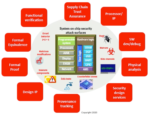
A comprehensive overview of the various attack vectors and the countermeasures EDA offers was presented. This diagram really drove home the breadth of the problem. It’s included at the top of this post. Rather than spend an hour on this chart (DAC presentations are short) Steve chose to focus on formal methods. It turns out there are a number of specialized formal security applications that can prove things like data integrity, so this is a promising approach to verify compliance. The breadth of this technology is summarized in the diagram below.
Steve ended his discussion with a vision of top-down verification of hardware security. Similar to approaches used for early hardware/software verification, he advocated a top-down approach to model the entire system in package, including the chip, interposer, package and board. This will allow the development of attack tests at a high level that can be used later in the design flow to verify the robustness of the system.
There are industry-level efforts to advance the cause as well. Cadence is working with several organizations to advance the state of testing and compliance, including Accellera. Security is a daunting task; it was good to hear about some positive momentum from Cadence.
If you have a DAC pass, I encourage you to watch this entire designer track session. I believe the material will be available online for an extended period of time. You can find this session on The Modern Automobile: A Safety and Security “Hot Zone” here.