
Today’s Market Requirements
Complex electronic devices and (sub)systems work for us in important applications, such as aircrafts, trains, trucks, passenger vehicles as well as building infrastructure, manufacturing equipment, medical systems and more. Very high reliability (the ability of a product to meet all requirements in the customer environment over the desired lifetime) is becoming increasingly important. Big Data and AI (Artificial Intelligence) are making humans even more reliant on electronic systems and will make insufficient reliability more painful, costly, even deadly. At the recent DesignCon 2020 I had the opportunity to learn how ANSYS is enabling engineers to design highly reliable products.
Brief ANSYS history, focus and key acquisitions
ANSYS, based near Pittsburgh, Pennsylvania, was founded in 1970 and employs now about 4,000 experts in finite element analysis, computational fluid dynamics, electronics, semiconductors, embedded software and design optimization work. ANSYS is well known as partner for very demanding customers in space and aircraft applications. ANSYS grew rapidly, also by acquiring other EDA suppliers. They bought and integrated Ansoft Corp. in 2008 and Apache Design Solutions in 2011. In May 2019 ANSYS acquired DfR Solutions to deepen their capabilities in electronics reliability, including simulation of semiconductor packaging and PCBAs as well as a physical laboratory capable of characterization and library generation as well as analysis and testing of a broad range of electronic parts (semiconductors, displays, batteries, etc.). DfR’s best known product is Sherlock, a powerful pre- and post-processor for reliability prediction of dice, packages, and PCBs subjected to thermal, thermo-mechanical, and mechanical environments.
The value of FEA tools and accurate inputs (libraries)
Analyzing the reliability of prototypes and/or pre-production units with a test-fail-fix approach is costly, time consuming and provides results very late in a product’s life cycle. ANSYS’ Sherlock applies finite element analysis (FEA) and enables engineers to easily assess a hardware design’s reliability, accurately and at the beginning of a design cycle. This also allows designers to evaluate trade-offs (e.g. different architectures, geometries and materials) early and across a wide range of conditions, to achieve optimal results.
Summary of the ANSYS Design for Reliability presentation at DesignCon 2020
In a fully-packed conference room, ANSYS’ Kelly Morgan, Lead Application Engineer, presented three examples for failure mechanisms, where Sherlock can add significant value. Sherlock and ANSYS Mechanical apply physics of failure principles to predict hardware reliability for: 1) Low-k cracking, 2) Solder joint fatigue and 3) Micro-via separation. The pointers lead to much more information than the paragraphs below can provide.
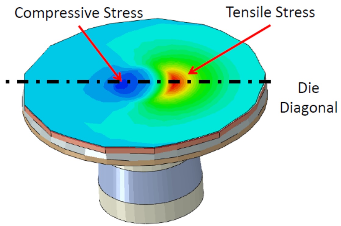
To 1) Low-k cracking: Dielectric material with low dielectric constant (k) reduces parasitic capacitance, enabling higher circuit performance and lower power dissipation. However, its low mechanical strength leads sometimes to cracks in the dielectric, due to thermal-mechanical forces from differences in coefficient of thermal expansion (CTE) that occur during reflow or thermal cycling. Acoustic inspection can reveal these cracks. If the low-k material is found to be cracked at this late stage of product’s introduction, it can trigger a dreaded redesign cycle. In contrast, Sherlock and ANSYS Mechanical allow an IC designer – at the beginning of a project – to predict such failures, take corrective actions right away and pre-empt such problems from occurring.

Figure 1: CTE differences between a copper pillar and a die lead to both compressive and tensile stress — and impact adjacent transistors’ performance as well as reliability Courtesy: ANSYS
To 2) Solder joint fatigue: Many integrated circuits (ICs) have traditionally used lead (Pb) free solder bumps as connections to other dice, the package, and even the printed circuit board (PCB). Different CTEs and temperatures in adjacent layers make the materials expand and contract differently. These thermal-mechanical forces, as well as vibrations, mechanical shock, etc., cause strain on the solder bumps and may lead to cracks within the solder bumps and/or at the interconnect surfaces. More recently, copper pillars have become popular because they allow much tighter spacing than solder bumps. However, these interconnects are more rigid and can fail faster, depending on the strain being applied. Sherlock’s and ANSYS Mechanical’s multi-physics capabilities allow users to easily and accurately predict the reliability of such interconnects and, if needed, drive needed changes early in the design cycle.

Figure 2: Cross section of a solder joint and how different CTEs cause materials to shrink or expand Courtesy: ANSYS
To 3) Micro-via separation: As spacings in electronics get smaller and smaller, the use of micro-via technology in PCBs has exploded. Micro-vias stacked as much as three or four high have become very common. However, if these designs do not use the right materials and geometries, the micro-vias can experience unexpected cracking and delamination.
Thermal-mechanical stress, moisture, vibration and other forces, can lead to separation of micro-vias, as well as delamination from copper traces at the top or bottom of plated through-hole vias (PTHs). Sherlock analyzes these problem areas, considers overstress conditions during reflow and/or operation and can predict when fatigue will lead to interconnect failures between vias, PTHs and routing layers and/or under bump metal (UBM) contact points.

Figure 3: Likely reliability risks in electronic products during manufacturing and operation Courtesy: ANSYS
Design flow integration of Sherlock
Even a best-in-class point tool, like Sherlock, needs to be integrated into a user-friendly and high productivity design flow, to provide its full value in a customer’s design environment. Only smooth data exchanges with up- and down-stream tools enable engineers to utilize Sherlock’s many capabilities quickly and efficiently. Flow integration minimizes scripting, data format translations as well as error-prone and time-consuming manual interventions. Sherlock interacts with ANSYS’ Icepak and ANSYS Mechanical to combine these tools into a high productivity and very reliable design flow for reaching the “ZERO DEFECTS” goal more and more applications require. Learn more about ANSYS Sherlock HERE.

Figure 4: Important stages where, in a hardware design process, Sherlock can avoid surprises Courtesy: ANSYS
Share this post via:


Comments
There are no comments yet.
You must register or log in to view/post comments.