

Electronic design automation has evolved to an extent that the complex chips with tens of billions of transistors frequently produce first pass functional prototypes from the manufacturer. What makes this so incredible is that such a small portion of the possible states of electronic operation are actually tested in the simulation of the chip. Figure 1 takes the example of a very simple electronic function, a 32 bit comparator, that compares two thirty-two bit numbers and determines whether one of them is equal to, less than or greater than the other. One might naively assume that this requires 2^32 comparisons of the two numbers. It doesn’t. If it did, then a caveman who was given one of today’s state of the art computer servers 565,000 years ago would just have completed the calculation. EDA history is made up of innovations that preempt the need to check every possible state of an electronic circuit, or 100% of the state space as design practitioners would say.
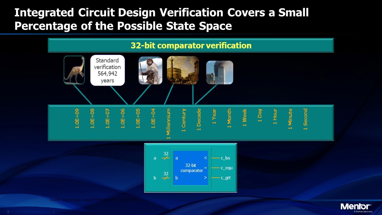
Figure 1. Simple comparison of two 32-bit numbers would require 565,000 years with a state-of-the-art computer if each possible pair of numbers had to be compared
The question then arises, “if we can reliably simulate the behavior of chips with billions of transistors, can we extend the technology to more complex systems like cars, planes and trains?” Or, if we can do this for the electronic behavior of a chip, could we extend it to the mechanical, thermal, aerodynamic or other simulated behavior of a complex system? Inverse reasoning suggests that the answer is “yes”. The reason is that the electronics of systems like cars and planes are becoming so complex that, if we can’t automate the design and simulation, there is no other known solution. Humans certainly can’t analyze the complexity of such a system (Figure 2).
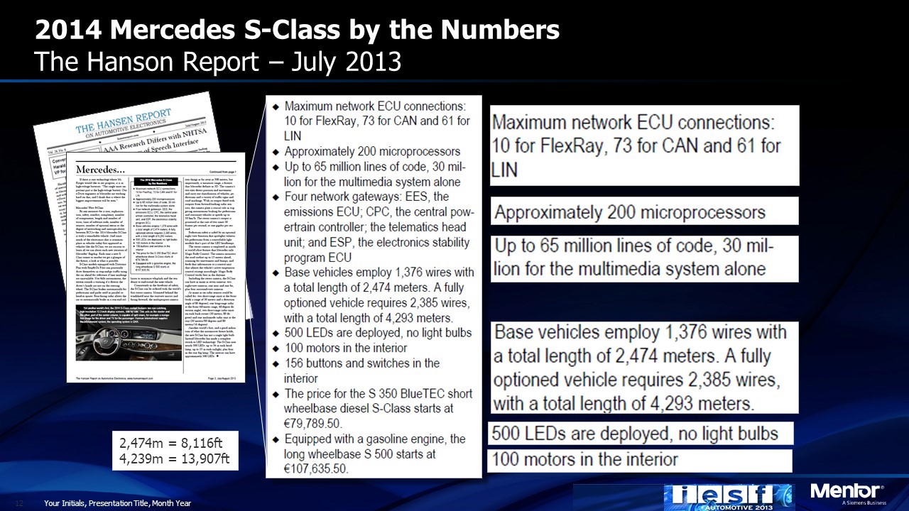
Figure 2. Electronic and wiring complexity of a 2014 S-Class Mercedes
It has taken sixty years to evolve the software to accurately simulate the electrical behavior of chips. How long will it be before we can do the same for an entire car or plane? And how will cars and planes be designed in the meantime?
For the automotive and aerospace industries, mechanical design simulation and verification evolved long before electronic simulation. Dozens of mechanical computer automated design, or CAD, companies emerged in the last thirty years. Today simulators that model most of the mechanical design, as well as the manufacturing processes to produce them, are available from companies like Siemens, Dassault and Parametric Technologies. These simulators also analyze aerodynamics and thermal effects.
It’s just in the last three decades that the electronics in cars and planes have increased in complexity to such a level that humans can no longer manage the data required to create an optimized, cost effective design without errors (not to mention protections against hacking).
It’s easy to assume that the design of a car you buy has been verified by driving prototype cars for thousands of miles in all types of weather conditions. It probably has. Before a manufacturer can build that prototype, extensive verification must be performed. How is that done? It all comes down to a methodology called “abstraction”. Requirements for the design of a vehicle are described at a high level and then refined to provide greater detail. Each level of abstraction of the data is analyzed on a computer or with a physical prototype of a subsystem.
The same is true of integrated circuits. Figure 3 shows the various abstractions used to describe, simulate and verify the performance of a chip.
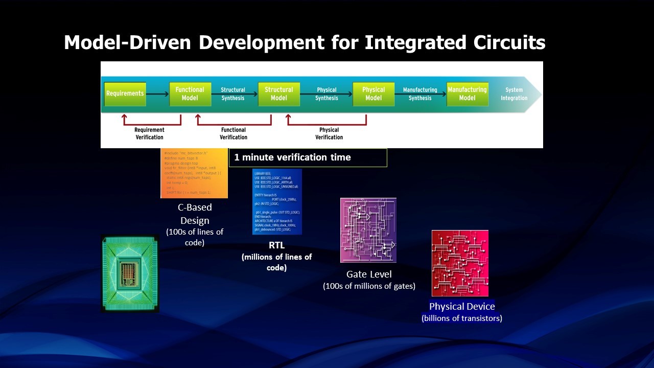
Figure 3. Four “abstractions” used in the design of integrated circuits
Although relatively new, ICs are increasingly being described in a high level language like C++. This description is relatively compact so simulations of the entire chip, or the critical performance portions of it, can be run quickly. That description is automatically “synthesized” into the next level of abstraction called “RTL” or register transfer logic that is described by a language such as Verilog, VHDL or System Verilog. This level of abstraction is much more detailed, describing logical operations of the chip. Simulations of the full chip typically take up to twenty-four hours so the building blocks of the chip are rigorously simulated before integrating them step by step until the whole chip that can be simulated. Once the designer is satisfied with the RTL simulation, the database is synthesized into a description of the actual logic gates creating what is called a “net list”. The design is synthesized into a description of the physical layout of the transistor on the silicon and then transformed into a language (GDS2) that the photomask generator can understand and can convert into the actual photographic negative that is used to manufacture the chip.
System design has evolved a similar design approach but systems engineers refer to it as the “V Diagram” (Figure 4). A difference between the “V” approach and that used
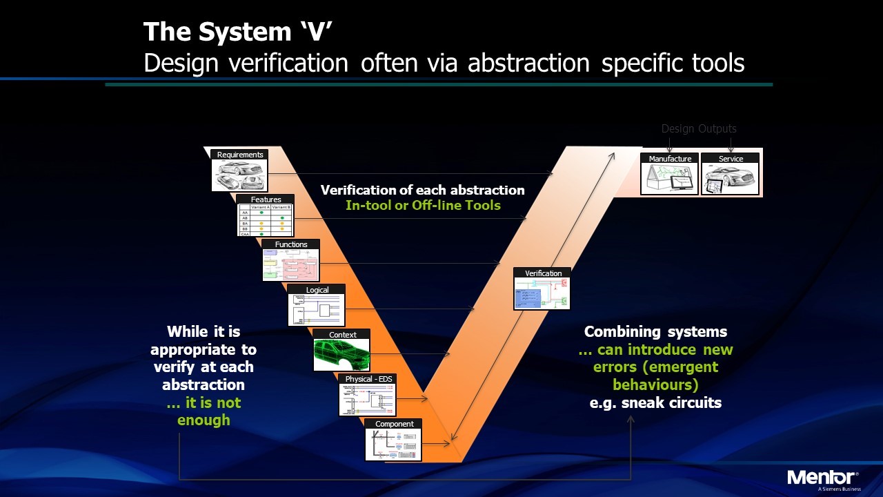
Figure 4. System “V” diagram showing the path from high level abstraction to greater detail followed by integration and verification at each level of abstraction
by IC designers is that the system designer is likely to build a physical prototype of each subsystem once the design is refined to the level of a physical description. That prototype can then be tested by inserting it into a laboratory mockup of the entire vehicle using what is referred to as “hardware in the loop” testing. Integration testing can also be performed with hardware in the loop but increasingly those subsystems are tested in a “virtual” environment where the parts of the vehicle that are connected to it provide inputs and react to its outputs in a simulated virtual environment.
This whole methodology is being disrupted because of growing complexity. Once we begin to develop truly autonomous vehicles, the approach will become totally inadequate because the number of tests that must be performed exceed the capability of physical testing (Figure 5). To test an autonomous drive vehicle would require more than eight billion miles of driving, according to Akio Toyoda, CEO of Toyota.
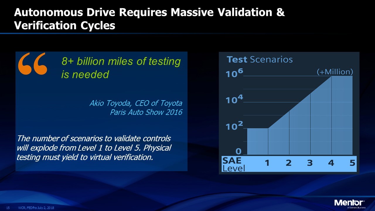
Figure 5. More than 8 billion miles of driving would be required to physically test an autonomous vehicle. Instead “virtual” verification must be adopted
A manufacturer would have to send out a fleet of 300 cars, driving at 60 mph for fifty years. Not very practical for introducing a new model each year.
Another reason that automotive and aerospace design must become virtual is that optimization has become too complex. Consider the wiring alone. With more than 1.5 miles of wiring in a car, forty miles in a small business jet and over one hundred in a commercial aircraft, there is a critical need to analyze tradeoffs among variables like weight, cost, performance, signal integrity, etc. Finding an optimum combination is far beyond the ability of the human brain. The same can be said for optimizations of the electrical subsystems, called electronic control units or ECUs in a car, or line replaceable units or LRUs, in an airplane. These ECUs contain multiple chips and embedded software to handle processing such as control of brakes, transmission or engine ignition. They are complex enough to require simulation to assure that the inputs and outputs perform as specified. The additional opportunities for problems arise when the ECUs are tested in a system environment. Even if an automotive OEM were lucky enough to produce a functioning car without a virtual simulation, debug of future problems would be difficult or impossible without a simulation.
Modern cars contain up to one hundred million lines of software code. It’s safe to assume that this code will contain bugs. The challenge for the automotive OEM is to find a way to react quickly and update the software in every similar vehicle on the road when a bug is discovered. Otherwise, the OEM could be liable for all accidents that occur once the bug is known. Tesla has developed an infrastructure to make this possible. The other challenge is to design the car in such a way that mission critical systems can be isolated. Many of the most publicized hacks of vehicles have come from intrusion of the vehicle through the infotainment system that is tied to the CAN bus, giving access to more critical systems like the brakes, transmission and engine.
How long will it take until automotive OEMs design the entire vehicle, as well as the assembly line for building it, in a totally virtual environment on a computer. The industry is farther along than you might think. Most of the mechanical design and manufacturing operations are already done that way. The remaining challenges include much of the electronics. That’s why Siemens, who provided software for all aspects of mechanical, aerodynamic, thermal and manufacturing simulation, decided to acquire an EDA company, Mentor Graphics.
System simulation of the electronics, as well as testing and optimization that involves “cross domain” testing among electrical and mechanical systems, remains very challenging. Wiring architectural tradeoffs and automatic generation of the design of the wire harness is essentially automated today. Automation of design and verification of other vehicle electronics will require development of abstractions that can be used to analyze multiple ECUs operating in concert with one another as embedded software is executed in the vehicle. The abstractions must be at a high enough level that they can be simulated at something like 100X the real time execution but be detailed enough that an engineer can analyze the inner workings of an ECU to find a design bug or test an optimization alternative.
How long will this take? Not that long. It has to happen over the next decade or two or we won’t be able to design the next generation of cars and planes.
Share this post via:


Consolidation and Competition: Who is Winning the $4.5 Billion Interface IP Race?