You can only design and optimize for low-power SoC designs if you can actually simulate the entire Chip, Package and System together. The engineers at ANSYS-Apachehave figured out how to do that and talked about their design for power methodology in a webinar today. I listened to Arvind Shanmugavel present a few dozen slides and answer questions in just about 33 minutes of time. In a week or so you can view and listen the recorded webinar here.

Arvind Shanmugavel
Here’s what I learned:
A few large markets are driving the need for low power design. The market sizes are:
- Mobile, > $30B
- HPC and Networking, > $35B
The top four challenges to achieve this low power SoC design are:
- Power Efficiency (power-aware, thermal-aware design)
- Ultra-low supply voltages
- Complexity (Semi IP re-use, 20nm node, 3D IC)
- Costs
EDA tools that can help:
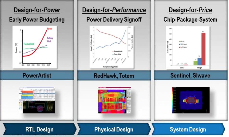
- RTL Design – Design for Power with PowerArtist
- Physical Design – Design for Performance with RedHawk, Totem
- System Design – Design for Price with Sentinel, SIwave

How do I get RTL Power Convergence? The old method is to do gate-level power analysis, while the new method is RTL power analysis instead.
Power reduction and debug is possible at the RTL level. If you can find clocks that are toggling, but not needed in a block, then you can change your code and save power.
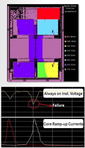
How would I measure my semiconductor IP power integrity and reliability? Analyze, view coverage and create modeling for IP blocks using tools like: Totem and RedHawk. Here’s an example where a four-core SoC had an IR drop failure with one of the cores during power-up.

To performa SoC Power integrity and reliability, what is needed?
- Capacity (full-chip, hierarchical)
- Accuracy (compared to silicon)
- Analysis (with and without vectors, EM, ESD).
Electromigration should have a sign-off to ensure reliability. Checks include:
- Grid prototype
- Driver checks
- Signal EM analysis
- Power EM
- Pad currents
- Sign off
To ensure ESD integrity coverage requires analysis at all three stages of development:
- Floorplan
- IP Level with I/O Ring
- Full-Chip sign-off
System integrity requirements (Analyze with Sentinel)
- Accurate (using 3D full-wave, Chip+Package+System)
- Power Integrity (PI) / Signal Integrity (SI)
- Thermal integrity
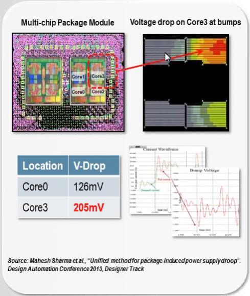
Example: Multi-chip Package Module with 8 cores, shows a failure due to IR drop on one of the cores.

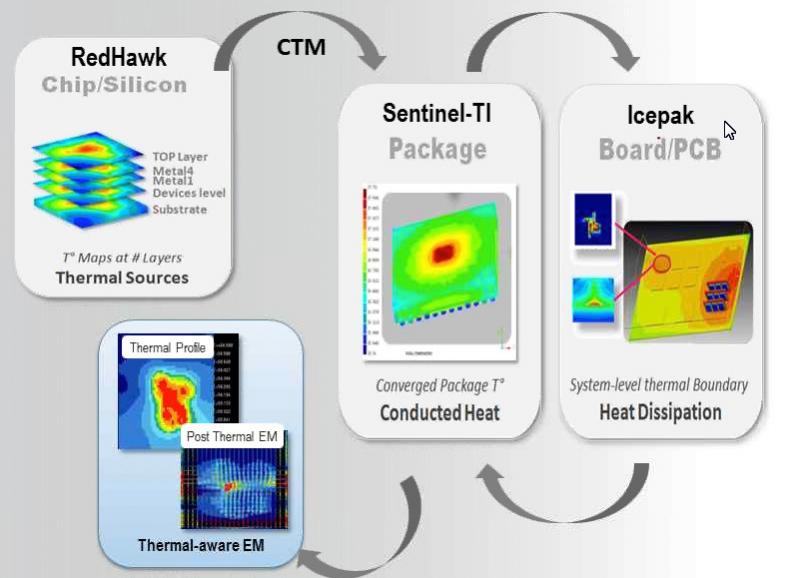
CPS Thermal Integrity is achieved by using a flow of three EDA tools:
- Create a Chip Termal Model (CTM) using RedHawk
- Use the CTM when simulating a Package (Sentinel-TI) or Board (Icepak)
- Die thermal profile can be used to visualize effects of EM

For ESD analysis the tool used is called PathFinder.
Q&A
Q: Which of these tools are transistor level?
Totem is transistor-level simulation for power, noise and reliability.
Q: Why is it necessary to model the package for on-die IR drops?
There are three aspects: Source of noise, media of noise propagation, and the victim characteristics?
Q: What type of package models does RedHawk accept?
RLC parasitic is the most popular model. Package designers also create S-parameter models, which are accepted by RedHawk.
Q: Are their any industry standards for the types of analysis that you offer?
Totem and RedHawk have different standards. For IR drop analysis you need on-state analysis. Leakage uses an off-state analysis.
Q: What types of on-die models are available for the complete switching of the chip?
RedHawk can analyze the complete die behavior and create a CPM – Chip Power Model, has both impedance and transient current characteristics.
Q: Do we need to supply VCD files to RedHawk?
Yes, you can use VCD stimulus as an input to RedHawk for vector-based analysis, or in a mode without any input vectors based on statistical activity.
Q: Who has validated these results versus silicon?
Several of our customers have published their silicon correlated results.
Further Reading
- An EDA Acquisition that Worked
- RTL Design For Power
- Robust Design <- Robust Flow <- Robust Tools
- Power and Reliability Sign-off – A must, but how?
- Efficient Power Analysis and Reduction at RTL Level
- Full Chip IR Drop Analysis using Distributed Multi Processing
- Today’s Program is Brought To You by the Letter A
lang: en_US
Share this post via:


Comments
There are no comments yet.
You must register or log in to view/post comments.