In this previous article, I was suggesting that certain chip makers may take a serious look at a disruptive way to look at Moore’s law, as they may get better ROI, profit and even better revenue. The idea is to select technology node and packaging technique in order to optimize the Price, Performance, Power triptych and manage chip development lead time to optimize Time To Market (TTM) and cost. Only a complete business plan would confirm the validity of this assumption, but we think it could be a new direction to be explored, so we propose some tracks.
The goal for a chip maker supporting “Less Than Moore” is not to displace the Qualcomm or Samsung, following Moore’s law and getting back more than enough revenue to invest and develop IC ever more integrated, targeting smaller technology node, supporting the type of Roadmap you can see below. This roadmap from Samsung shows Discrete Application Processor and Baseband Processor paths, as well as in parallel a roadmap for cost sensitive systems with Integrated (Application + BB) processor.
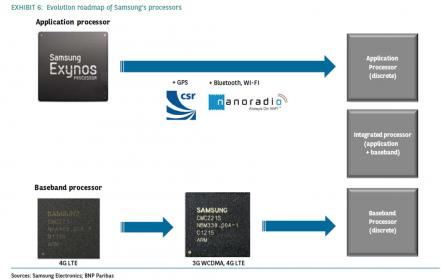
Following Less Than Moore (LTM) could be beneficial for some of the (many) followers of the two above mentioned leaders: the AP market is so competitive that only a few could be successful if they all play Moore’s law. As previously discussed, developing IC in a more mature technology node (say 28 nm instead of 14 or even 20 nm) will certainly offer lower development schedule: EDA tools have been stabilized, as well as technology related models, the technology node require less “weird techniques” at the layout stage, so finally the design cycle is expected to be shorter: better TTM and lower development cost. On the process side, when a technology node is more mature, processing the wafer requires less operation and less mask steps, so the wafer fab cycle is faster and the mask cost lower: again better TTM and lower development cost. But what kind of approach could keep development cost lower than following Moore’s law, still allowing being successful on the Mobile market? Which means trying to offer the best (Price/ TTM / MIPS per Watt) compromise. Let’s have a look at various approaches like FDSOI, Multi Chip Package (MCP) and 3D Chip Processing & Packaging, and verify the technical and economic feasibility.
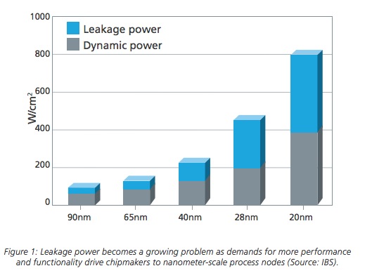
FDSOI stands for Fully Depleted Silicon On Insulator, and recently ST and ST-Ericsson have fabricated a smartphone chip based on 28nm FD-SOI in which the ARM dual Cortex-A9 CPU can reach 800MHz at a mere 0.6V and over 1.5GHz at just 0.85V. The benefits better performance and energy efficiency across the full range of power supply, exceptional performance at very low Vdd (e.g., 0.6V-0.7V), enhanced efficiency of DVFS (Dynamic Voltage and Frequency Scaling) and significant boosts in performance and leakage control through the optional use of a back-bias.
If we look at the above picture, we see that leakage power is becoming the more important part of power dissipation for traditional CMOS technologies, at 28 and 20 nm nodes. It sounds quite cleaver to target FDSOI and minimize leakage. But does it really work? The picture below shows the evolution of leakage power of Cortex ARM9 in function of the performances (Frequency axis) for 28LP (VDD=1V), 28G (VDD=0.85V) and 28FDSOI (VDD=0.9V). If we consider an Application Processor for Wireless Application, we should compare 28LP and 28FDSOI. That we can see is:
- For the same leakage power budget (20 mW), FDSOI provides 30% increase in frequency, or 1,32 GHz
- Or, at the same frequency (1 GHz), one order of magnitude difference in leakage power, with 10 mW for 28FDSOI compared with 100 mW for 28LP
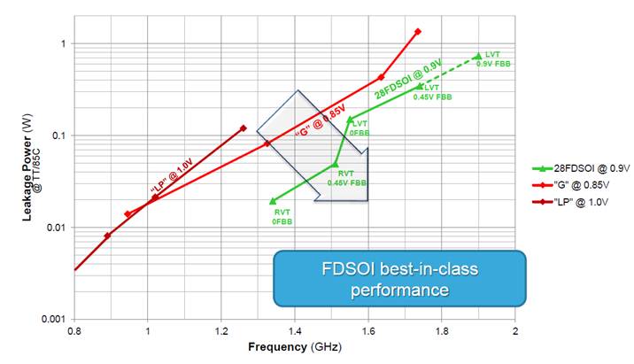
So, a rough approximation could be to consider that using 28nm CMOS transistor on FDSOI wafer provide the same performance than using 20nm CMOS transistor on Bulk Silicon wafer, and this for the same power budget. Using FDSOI also provide another optimization path, with substrate biasing usable as a powerful way to get very high performance when needed: on the above picture you will note (green curve) that, when applying 0.45V Forward Body Bias (FBB), you increase ARM9 frequency from 1.55 GHz to 1.75 GHZ, at the same power adding cost than when you increase ARM9 frequency on Bulk 28G. The below picture illustrates the principle of the FBB, as well as showing a MEB view of the Silicon structure.

FDSOI looks attractive, but it could be wise to check if there are any drawbacks…
Design Flow and EDA tools: FD-SOI is fully compatible with traditional planar technology, it does not disrupt the design methodology, meaning designers keep the same flows and tools as what they would use with conventional CMOS design.
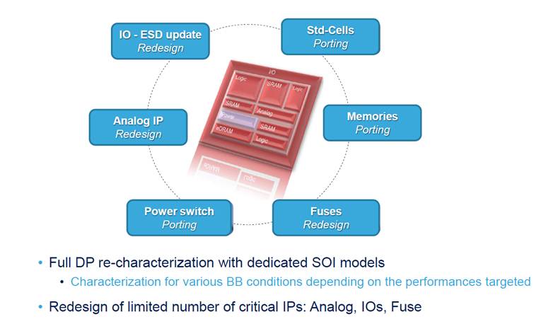
Design IP and Libraries: at this stage, you realize that you need to do at least the porting of Std-cells libraries, memories or power switches. But you need to redesign critical IP: IOs, ESD structures, Fuses and Analog IP. This can be a serious drawback if the chip maker does not usually develop his owns critical IP like PLL or SerDes. If we take the example of the Application Processor, you must find an IP vendor who develop and sell: USB 2.0 & USB 3.0 PHY, MIPI D-PHY & M-PHY, HDMI PHY, LPDDR2 or 3 PHY and probably a couple of PLL…
This can be a chicken and egg problem, if FDSOI adoption is high enough, IP vendors will redesign these IP, but if it’s not the case, the chip maker will have to rely on design service third party to develop it. The problem here will be a cost adder, compared with off-the-shelves IP, and even more critical a higher risk compared when using a Silicon proven IP from an IP vendor (which is not necessarily the case when you use the most advanced technology node, then the Analog IP is not yet Silicon proven…).
So, FDSOI is clearly an attractive technology, especially for wireless AP, as it allows minimizing drastically the power budget (by almost an order of magnitude for the leakage power), or increasing the processor core frequency. Using FDSOI is equivalent to design on one technology node back (28nm instead of 20nm), and benefit from lower mask cost and process complexity. This benefit should be balanced with extra cost and risk link to the redesign of all critical Analog IP, such cost and risk being minimized when/if FDSOI will see enough adoption level.
In fact, studying Less Than Moore techniques require more than two posts, you will have to stay tuned for a next post dealing with Multi Chip Packaging or 3D Chip integration, as these technologies could be promising too!
From Eric Esteve from IPNEST
Qualcomm Roadmap Clarification (about the previous article)
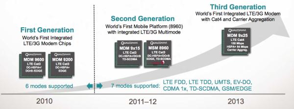
Remark: when I have shown this picture from Qualcomm in the previous “Less Than Moore” article , I was under the impression that it was their Mobile product roadmap. In fact, it’s not, and the meaning of this slide is to show the evolution of the Modem IC (MDM products) supporting more modes at every generation, or being integrated with the AP (MSM products = Single die Modem + AP). I thanks Edgar Auslander for providing this meaningful information (the key message being that Qualcomm is offering today their 3[SUP]rd[/SUP] generation of LTE Modem, far ahead of the competition) and invite him to share the part of Qualcomm roadmap missing here in Semiwiki… if possible!
Share this post via:


Comments
0 Replies to “Can “Less than Moore” FDSOI provides better ROI for Mobile IC?”
You must register or log in to view/post comments.