Banner 800x100 0810

The Lost Opportunity for 450mm

The Lost Opportunity for 450mm
by Scotten Jones on 04-15-2022 at 6:00 am

450mm Wafer SemiWiki


I spent several days this week at the SEMI International Strategy Symposium (ISS). One of the talks was “Can the Semiconductor Industry Reach $1T by 2030” given by Bob Johnson of Gartner. His conclusion was, that $1 trillion dollars is an aggressive forecast for 2030 but certainly we should reach $1 trillion dollars in the next 10 to 12 years. He also noted that the industry would need to nearly double to achieve this forecast (a 73% increase in wafer output). He further forecast ~25 new memory fabs at 100K wafers per month (wpm) and 100 new logic or other fabs at 50K wpm (300mm). It immediately struck me, where are we going to build all these fabs, where will the people come from to run them, and where would we get the resources required. Wafer fabs are incredibly energy and water intensive and produce large quantities of greenhouse gases.

At the same conference there was a lot of discussion of environmental impact. Across the entire semiconductor ecosystem there is growing awareness and actions to reduce our environmental impact – reuse, reduce, recycle.

What does this have to do with 450mm wafers you ask.

A 450mm wafer has 2.25 times the area of a 300mm wafer. If you build 450mm wafer fabs with the same wpm output as 300mm fabs you need approximately 2.25 times fewer fabs (even less due lower edge die losses), 25 memory fabs becomes 11 memory fabs and 100 logic or other fabs becomes 44 fabs. These are much more manageable numbers of fabs to build.

If you look at people required to run a fab, the number of people required is largely based on the number of wafers, by running fewer-bigger wafers the number of people required is reduced.

When 450mm was being actively worked on, the goals where the same tool footprint for the same wafer throughput (likely not achievable), the same chemical and gas, and utility usage per wafer, a 2.25x reduction in usage per unit area. There was a recognition that beam tools such as exposure, implant, and some metrology tools where the wafer surface was scanned would have lower throughput but even accounting for this my simulations projected a net cost reduction per die for 450mm of 20 to 25%.

Unfortunately, the efforts to develop 450mm have ended and the only 450mm wafer fab has been decommissioned. The 450mm effort was different than past wafer size conversions, at 150mm Intel was the company that led the transition and paid for a lot of the work and at 200mm it was IBM. At 300mm a lot of the cost was pushed onto the equipment companies, and they were left with a long time to recover their investments. At 450mm once again the costs were being pushed onto the equipment companies and they were very reluctant to accept this situation. In 2014 Intel (one of the main drivers of 450mm) had low utilization rates and an empty fab 42 shell and they pulled their resources off 450mm, TSMC backed off, equipment companies put their development efforts on hold and 450mm died.

At this point it is likely too late to revive 450mm, ASML have their hands just trying to produce enough EUV systems and getting high-NA into production. High-NA EUV systems for 300mm are already enormous – difficult to transport systems, making much bigger 450mm versions would be an unprecedented engineering challenge. I do think there is important lesson for the semiconductor industry here. The semiconductor companies have a long history of short-sighted squeezing of their suppliers on price often to their own long term detriment. Starting wafers are an excellent example, prices have been driven down so low that it isn’t economical for the wafer manufacturers to invest in new capacity and now the industry is facing shortages. It is only shortage driven price increases that are now finally making new investment economical.

Over the next decade, as we potentially double our industry while trying to reduce our environmental footprint our task would be much easier with 450mm wafer, but unfortunately our inability to work together and unwillingness to take a long term view has left us without this enhancement in our tool kit.

Also Read:

Intel and the EUV Shortage

Can Intel Catch TSMC in 2025?

The EUV Divide and Intel Foundry Services


5G Core – Building An Open, Multi-Vendor Ecosystem

5G Core – Building An Open, Multi-Vendor Ecosystem
by Kalar Rajendiran on 04-14-2022 at 10:00 am

5G Potential for Businesses

For those not familiar with Fierce Technology, this firm offers a one stop place for news, analysis and education in the areas of telecom, wireless, sensors and all related electronics markets. They organize popular events such as the 5G Blitz Week, Sensors Innovation Week series, Sensors Converge and many more. These events facilitate the exchange of critical information among industry professionals, with the intended goal of accelerating the advancement of the industry as a whole.

Fierce Technology hosted their annual “5G Blitz Week: Spring Edition” as a virtual event in March. The topics covered included fixed wireless access (FWA), Open RAN, Private Networks, open core and more and related opportunities, applications and deployment challenges. The 4-day event was packed with interesting talks and panel discussions on 5G evolution and the roadmap to 6G. One such discussion was a panel session titled “5G Core – Building An Open, Multi-Vendor Ecosystem,” with participants representing Achronix, Google, HCL, Meta and Red Hat.

The discussion was moderated by Dave Bolan, Research Director at the Dell’Oro Group. The session started with an opening keynote by Ersilia Manzo, Director, Global 5G Solutions at Google. The panelists were Nick Ilyadis, senior director of product planning at Achronix, Parviz Yegani, VP CTO, Office Industry Software Division at HCL, Xinli Hou, Connectivity Technology & Ecosystem Manager at Meta and Fatih Nar, Chief Architect Telco Solutions at Red Hat. Fatih also delivered a closing keynote.

It is appropriate to present a couple of slides from Fatih’s closing keynote before synthesizing the panel discussion.

In the age of open-source, open architecture, open ASIC, etc., organizations such as the Telecom Infra Project (TIP) have been working toward accelerating the development and deployment of open standards. The question is, will an open core ecosystem become a reality for communications service providers (CSPs)? What is needed from the different players within the ecosystem? These are some of the questions that this panel session addressed. The following are excerpts from that panel session. You can listen to the entire panel session on-demand, by registering at Fierce Technology. 

Google – Ersilia Manzo (opening keynote)

Over the last decade or so, the relationship between telcos and vendors has changed. The focus has shifted from “what to build” to “how to build.” The telco industry has been moving toward a cloud-native deployment and evolving to a service delivery platform, eliminating the boundaries between network and services. Elements that were shipped with the network functions such as the orchestrator and operating systems are no longer integrated but are delegated to the cloud-native platform. Cloud-native networking offers the benefits of agility, flexibility and cost-efficiencies to CSPs and is expected to become the dominant approach in the future.

With the open-standard based approach and the resulting disaggregation, more parties have to get involved to build the network. In the past, the industry relied on interoperability of finished products. Now, the industry needs co-development and cooperation between the parties that are building the networks.

Google believes there are three main elements that are critical to the success of the cloud-native, multi-vendor 5G network.

  • Standards: These are no longer just documents that are produced over months or years by industry organizations. Now, standards include code releases such as Kubernetes and PDKs that help accelerate services deployment and shorten validation cycles.
  • Contributions: Process of fixing and contributing code back as a community is key.
  • Partnerships: Must truly involve cooperation and co-development.

Achronix – Nick Ilyadis

The demand for high performance at low latencies without compromising on power has led to the use of heterogenous compute platforms to support many of today’s applications. A heterogeneous compute platform is a data processing unit (DPU) that may include a combination of CPUs, GPUs, ASICs, and FPGAs. The DPU is essentially an offload engine for the main CPU, to do hardware acceleration of data processing. As the 5G Core is deployed, and the standards evolve, there is going to be the need to offload the CPU and accelerate 5G Core. These offload engines will allow 5G Core to scale to higher capacities without the cost and burden of building more and more server installations.

Achronix’s products are data accelerators with their current high-end FPGAs supporting multiple 400G ports, PCI-e Gen5, 4 Terabits of memory bandwidth, Machine Learning Inference and more. These capabilities enable field-level adaptability and extensibility for the 5G Core as the standards and customization requirements evolve. Incorporating reprogrammable hardware within a 5G Core implementation is a great way to accelerate deployment of open core, 5G infrastructure in a multi-vendor ecosystem. For more details, you can download a recently published whitepaper titled “Enabling the Next Generation of 5G Platforms.”

HCL – Parviz Yegani

There are many use cases/scenarios to handle in a multi-vendor, multi-technology, multi-domain 5G environment. The domains include the Radio Access Network, the Transport Network and the 5G Core Network. A good solution should be able to support this requirement and allow any vendor to be able to plug-in their offering into the platform.

HCL is working on Augmented Network Automation (ANA), which is an evolution of the next generation of Self Organized Network (SON). This network management platform enables proactive network management which is key to the success of 5G Core adoption and deployment. ANA facilitates and allows for inclusion of various software solutions from 5G Radio vendors, RAN vendors, and network management vendors. A key feature of the ANA platform is its unified management console and is centered around comprehensive data visibility.

Meta – Xinli Hou

While Meta is not a 5G vendor or service provider, they do drive the advancement of connectivity through their involvement in projects such as the Telecom Infra Project (TIP). Compared to the wireless market of the past, the 5G market place is attractive to many varied use cases, thereby fragmenting the market. This necessitates customizing the solutions as per the use case.  The Open Core Network initiative within the TIP effort is focusing on what can be done to enable faster adoption of Open Core, Cloud Native, 5G by more service providers serving these fragmented market segments.

Red Hat – Fatih Nar

Zero touch provisioning is a hot topic these days. A key aspect of zero touch provisioning is ensuring security and trust. A Zero Trust architecture should be foundational to 5G. Red Hat is deeply involved in how Zero Trust can be implemented with Open Core, 5G solutions in a multi-vendor environment.

The 3rd Generation Partnership Project (3GPP) as a telecom body, focuses on standards that dictate how mobile applications work with each other. But defining applications’ scalability and maintainability falls on the shoulders of the vendors. Red Hat works with vendors on implementing scalability, to manage costs depending on the traffic demands.

Also Read:

Benefits of a 2D Network On Chip for FPGAs

5G Requires Rethinking Deployment Strategies

Integrated 2D NoC vs a Soft Implemented 2D NoC


WEBINAR: How to Improve IP Quality for Compliance

WEBINAR: How to Improve IP Quality for Compliance
by Daniel Nenni on 04-14-2022 at 6:00 am

webinar semiwiki improving ip quality

Establishing traceability is critical for many organizations — and a must for those who need to prove compliance. Too often, the compliance process is manual, leading to errors and even delays. A simple clerical mistake can invalidate results and lead to larger issues throughout the product’s lifecycle. Developing a unified, IP-centric platform can help organizations improve overall quality while meeting compliance standards, like ISO 26262.

Compliance standards, such as ISO26262, require the SoC developer to collect and document evidence of compliance during the design process. These documents need to prove that requirements have been met by tracing tests and test results back to requirements on an IP. They need to show that “defensive” design techniques have been used.

Save your seat >>

The Perforce/Methodics IPLM platform is designed to have IP at the center of a compliance workflow. So, what is an IP? An IP is an abstract model that combines the design data files (that define its implementation) and metadata (that defines its state). Although this model is well-known in the semiconductor industry, it can revolutionize a business by creating full transparency into how IP objects evolve across projects and teams.

By centralizing IP management, designers and developers can collaborate inside their tools while creating a traceable flow from requirements, through design, to verification. This is because all software, firmware, and hardware IP metadata is stored in a single layer on top of a data management system. This metadata is comprised of information such as dependencies, permissions, hierarchy, properties, usage, and more. With IPLM, organizations can automate processes by using metadata that was collected and stored through the design and verification steps to automatically build FuSa compliance documentation.

There are other advantages when moving to an IP-centric workflow besides meeting compliance. By attaching relevant metadata to each IP, organizations can have a single source of truth that enables reuse across projects and teams. Making the design transparent allows individual blocks to evolve at their own pace, boosting innovation and cutting down on development costs. Because all the information around an IP is managed with Perforce IPLM Software, organizations can retain the context and connection back to the rest of the design, as well as the requirements. This improves overall quality while meeting regulatory standards.

Furthermore, since everything inside of IPLM is treated as an IP, this enables the creation of a full system level hierarchical Bill of Materials.  This facilitates the generation of correct-by-construction full system configurations, including the desired versions of all hardware, software, and firmware design IPs as specified by the project level IP hierarchy. This enables traceability from the silicon back to the exact IP BoM used for tape-out. This also helps to eliminate costly errors introduced by manual and outdated methods of configuration management, such as spreadsheets or simple text files. These errors could lead to delayed tape-outs, improperly functioning silicon, ECOs, and mask re-spins.

Learn more about IP quality and compliance from Wayne Kohler — Senior Solutions Engineer at Perforce. Join a live discussion with him on Wednesday, April 27, 2022, at 12:00 PM – 1:00 PM CDT. He’ll review how to build a platform to improve traceability and what you need to consider when complying with ISO 26262.

Save your seat >>

Also read:

Future of Semiconductor Design: 2022 Predictions and Trends

Webinar – SoC Planning for a Modern, Component-Based Approach

You Get What You Measure – How to Design Impossible SoCs with Perforce


Intel and the EUV Shortage

Intel and the EUV Shortage
by Scotten Jones on 04-13-2022 at 10:00 am

Slide1

In my “The EUV Divide and Intel Foundry Services” article available here, I discussed the looming EUV shortage. Two days ago, Intel announced their first EUV tool installed at their new Fab 34 in Ireland is a tool they moved from Oregon. This is another indication of the scarcity of EUV tools.

I have been tracking EUV system production at ASML to-date and forecasted output looking forward. I have also been looking at fabs that have been built and equipped and fab announcements to estimate the future requirement for EUV tools.

My approach is as follows:
  • List out each EUV capable fab by company with process type/node and capacity by year. I estimate how many EUV exposures are required for each process and convert this to an EUV layer count forecast by year (exposures x capacity).
  • For each year I look at the type(s) of EUV tools ASML produces and estimate the throughput by tool type for logic and memory processes.
  • Outset the required tools by time to account for the time between a tool delivery and the tool being in production.
Some notes about demand:
  • Intel currently has 3 development fabs phases that are EUV capable and 1 EUV capable production fab although only the development fab has EUV tools installed. Intel is building 8 more EUV capable production fabs.
  • Micron Technology has announced they are pulling in EUV from the one delta node to one gamma. Micron’s Fab 16-A3 in Taiwan is under construction to support EUV.
  • Nanya has talked about implementing EUV.
  • SK Hynix is in production of one alpha DRAM using EUV for approximately 5 layers and have placed a large EUV tool order with ASML.
  • Samsung is using EUV for 7nm and 5nm logic and ramping up 3nm. Samsung also has 1z DRAM in production with 1 EUV layer and 1 alpha ramping up with 5 EUV layers. Fabs in Hwaseong and Pyeongtaek have EUV tools with significant expansion in Pyeongtaek underway and the planned Austin logic fab will be EUV.
  • TSMC has fab 15 phases 5, 6, and 7 running 7nm EUV processes. Fab 18 phase 1, 2, and 3, are running 5nm with EUV. 5nm capacity ended 2021 at 120k wpm and has been projected to reach 240k wpm by 2024. Fab 21 in Arizona will add an additional 20k wpm of 5nm capacity. 3nm is ramping in Fab 18 phases 4, 5, and 6 and is projected to be a bigger node than 5nm. Fab 20 phases 1, 2, 3, and 4, are in the planning stages for 2nm and another 2nm site is being discussed.

Based on all of these fabs and our estimated timing and capacity we get figure 1.

Figure 1. EUV Supply and Demand.

 Figure 1 leads to a couple of key observations:

  • There will be more demand for EUV tools than supply in 2022, 2023, and 2024. Our latest forecast is a shortage of 18 tools in 2022, 12 tools in 2023 and 20 tools in 2024.
  • Looking at the logic companies where the bulk of EUV demand is, TSMC has the most EUV systems with roughly one half of the systems in the world, Samsung is next and then Intel. Of the three companies Intel will likely be the most constrained by the supply of EUV tools. It wasn’t that long ago that Intel was pushing out EUV tool orders, likely a mistake they wish they could take back.

In summary, over at least the next three years, leading edge EUV based capacity will be constrained by the scarcity of EUV tools with Intel likely to be hardest hit.

Also read:

Can Intel Catch TSMC in 2025?

The EUV Divide and Intel Foundry Services

Samsung Keynote at IEDM


Python in Verification. Veriest MeetUp

Python in Verification. Veriest MeetUp
by Bernard Murphy on 04-13-2022 at 6:00 am

Python

Veriest held a recent meetup on a topic that has always made me curious – use of Python in verification. The event, moderated by Dusica Glisic (technical marketing manager at Veriest), started with an intro from Moshe Zalcberg (CEO of Veriest) and talks by Avidan Efody (Apple verification) and Tamás Kállay (Team leader, Veriest). I know Moshe is a fan of this concept as an example of extending gains in SW development to the HW world. This meetup digs deeper into Python in Verification.

Flows and stupid verification tasks

Avidan has background as a verification expert from Amazon, Intel and Apple, which makes him a serious authority in my view. He was careful to stress that none of what he talked here should be interpreted as methodologies at his current employer. Here, he was simply synthesizing his know-how gained over many years in using Python in his day-to-day verification activities. He also stressed that he is a verification expert using Python, not a Python expert drafted into verification.

This talk was an excellent introduction to “Why Python?” in verification. Consider Python’s assets. Many of us, not just in hardware design, already know and use the language., Python supports version control systems access and readers and writers for virtually any formats. It has increasing support from EDA companies and is already used in many production CAD flows. It has support for databases, CI/CD flows, etc etc. and is widely understood and supported for questions on e.g. StackOverflow.

From an applications point of view, Avidan cited 5 (the last one a stretch). First for building production flows such as tool wrappers and regression runners. Second for what he called stupid verification tasks: connectivity checks, clock/power gating, register checks. He made the point that tests of this type require design knowledge and spreadsheets but really don’t need SystemVerilog testbenches or randomization. Python can drive all of this. He pointed to the fact that Python can read RTL directly. There is a nice package called cocotb for testbenches, good enough for these purposes. And Python can read waveform files.

Python for designers who hate the verification team!

I really liked his next point – “Python for designers who hate us”. His point here is that a couple of decades ago, designers were doing verification themselves but stopped because verification split off into a separate team and became very complicated. Designers stopped verifying, not because they wanted to but because the whole process with UVM etc became too complicated and too slow to respond. Python provides them a way to return to unit/block testing, again using coctb etc, without having to wait on the verification team.

Avidan mentioned using Python to boost UVM flows by isolating stuff that can change quickly – sequences, configuration, assertion, checkers, etc, minimizing recompile requirements. The final application he mentioned is the “one language to rule them all” concept – that Python could replace UVM. He’s not a believer but he does know smart people who are pushing this direction 😎.

Developing bringup tests

Tamás described another interesting application – developing bringup tests before silicon arrives. In this context he needs to be able to support multiple platforms such as simulation, emulation, FPGA prototyping and of course silicon when available. What is important here is a unified development interface, supporting communication over standard hardware interfaces such as PCIe, JTAG and UART. In the early stages of development this supports development and debug of the tests, and later I would guess in support of post-silicon debug.

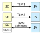
UVM obviously plays a role in test development but needs to sit under a superstructure which can span all these platforms. And which especially will work equally well with first silicon. For this reason the team built a client-server structure in which the servers are the various simulation platforms or silicon. These communicate through sockets with a client written in Python and running Python tests. The rationale for using Python was that the low-level SW team were already using Python to write tests in pytest. Also they found that many HW engineers already have at least some Python expertise. Which made adoption quite painless across both teams.

Tamás includes more detail on how they architected this system. He wrapped up by saying the approach worked well for them with some limitations. Perhaps not surprising for an in-house development to serve a custom purpose.

My takeaway

A few dreamers aside, production verification engineers are not aiming to replace UVM with Python. There will always be many clever things that UVM can do that Python cannot (easily). The purpose of Python development and usage around verification is to plug the holes in mainstream verification methodologies. For stupid tests and to support designers running their own verification. To speed up standard verification flows and to support silicon bringup test development. Could you do all that in standard UVM (or PSS) flows? Perhaps as an exercise, but would it have the flexibility of Python for these often-custom applications. With minimal learning across diverse HW and SW teams? That would be a stretch too, I think.

You can watch the meetup replay HERE.

Also read:

5 Talks on RISC-V

Ramping Up Software Ideas for Hardware Design

Verification Completion: When is Enough Enough?  Part II


Benefits of a 2D Network On Chip for FPGAs

Benefits of a 2D Network On Chip for FPGAs
by Tom Simon on 04-12-2022 at 10:00 am

Achronix FPGA 2D NoC

The reason people love FPGAs for networking and communications applications is because they offer state of the art high speed interfaces and impressive parallel processing power. The problem is that typically a lot of the FPGA fabric resources are used simply to move the data on or off and across the chip. Achronix has cleverly employed a two-dimensional (2D) Network on Chip (NoC) to offload this task from the FPGA fabric, freeing up significant area and offering better throughput and speed for all data transfers.

NoC Configuration

With claims like theirs it can be useful to see actual benchmark results that show the tangible benefits. First let’s start by describing their 2D NoC. In the Speedster7t FPGA, Achronix has implemented the NoC as 8 rows and 8 columns evenly spaced across the chip, each with two sets of unidirectional AXI compatible data paths that are 256 bits wide – all operating at 512 Gbps.

The 2D NoC can transfer data to and from the chip’s external interfaces, which include PCIe Gen5, GDDR6 DDR4/5 and Ethernet. The NoC not only supports a packet-based, master/slave transaction model, it also supports Ethernet data streams. In fact, the 2D NoC can move data from the Ethernet interface to the DDR memory without requiring any resources in the FPGA Fabric. This enables the Speedster7t with the 2D NoC to support 400 Gbps Ethernet with ease.

NoC vs FPGA Fabric Data Routing

To demonstrate several important aspects of the 2D NoC, Achronix has posted a video that goes through a stress test to see how the NoC performs in the real world. The test uses a data generator on one end of a NoC row/column and also has loopback logic on the other end. At the end of the loop there is a transaction checker. Each row and each column are fitted with this bi-directional configuration. The data generator, loopback logic and transaction checker are implemented in the FPGA fabric, which accesses the NoC through a Network Access Point (NAP).

The same set up was done for comparison using the FPGA fabric to route the data across the chip for each row and column. Without the NoC 40% more FPGA resources were needed to perform the routing across the chip. Even though the performance was equal at ~4.6 Tbps, the compile time for the design was 40% less for the NoC versus the FPGA data routing.

Visualizing FPGA Performance

The video highlights the two chips operating with monitoring attached to show data rates. Also, the loading of the entire NoC is shown visually in the Achronix tools. All the columns and rows showed green, meaning that they are well under full capacity in this particular test. The data rate in this test is determined by the data generator in each row/column.

Achronix FPGA 2D NoC Performance

Achronix has other examples in their latest white paper and 2021 webinar on their website of the efficiency and speed of using a NoC. For instance, in a case with internal congestion due to the addition of processing elements such as encryption/decryption, etc. a design with FPGA based routing may have to detour data routes around the congested areas. This can only add to timing closure headaches.

Conclusion

A high speed NoC offers a painless method of moving data at high speed, helping to fulfill the promise of FPGAs in data intensive applications. The 2D NoC on Achronix FPGAs offers high capacity and bandwidth combined with ease of implementation and rapid design closure. Seeing a heavily loaded stress test makes clear what is possible with the Achronix Speedster7t FPGA. The video is available on the Achronix website. Achronix also has several blogs that go into the specifics of their 2D NoC and how it can be used for 400 Gpbs Ethernet or other applications that perform compute intensive operations on data streams.

Also read:

5G Requires Rethinking Deployment Strategies

Integrated 2D NoC vs a Soft Implemented 2D NoC

2D NoC Based FPGAs Valuable for SmartNIC Implementation


Spatial Audio: Overcoming Its Unique Challenges to Provide A Complete Solution

Spatial Audio: Overcoming Its Unique Challenges to Provide A Complete Solution
by Kalar Rajendiran on 04-12-2022 at 6:00 am

20 Cones of Confusion

“If a tree falls in a forest and no one is around to hear it, does it make a sound?” is a philosophical thought experiment that raises questions regarding observation and perception [Source: Wikipedia]. Setting aside the philosophical aspects, if one wasn’t present where a sound was generated, the sound was lost forever. That’s until the advent of audio related technologies, starting with the microphones and loudspeakers. One could be seated in a far corner of a very large auditorium and still be able to hear a speech being delivered from the podium. Audio technology has advanced a lot since its early days. Loudspeakers have progressed through stereo, quad, 5.1, 7.1, large speaker arrays, Ambisonics, and Dolby Atmos. Headphones have advanced through stereo and multi-driver to binaural.

While audio technologies have progressively brought the listener closer to an aural immersion experience, they do not fully mimic the natural world experience. There is more to that experience than just hearing a sound. The phrase “you had to be there” to experience it has truth to it. This experience is termed 3D or Spatial Audio experience. The rendering audio technology should also sense the listener’s movement relative to the assumed location of sound source and continuously provide a realistic experience. Gaming, augmented reality and virtual reality have introduced more challenges to overcome for achieving a realistic aural experience.

So, how to mimic the aural experience of the natural world and the virtual world with audio electronics?

Recently, CEVA and VisiSonics co-hosted a webinar titled “Spatial Audio: How to Overcome Its Unique Challenges to Provide A Complete Solution.” The presenters were Bryan Cook, Senior Team Leader, Algorithm Software, CEVA, Inc. and Ramani Duraiswami, CEO and Founder, VisiSonics, Inc. Bryan and Ramani explained spatial audio, how it works, the importance of head tracking, challenges faced and their company’s respective offerings for a complete solution.

The following are some excerpts based on what I gathered from the webinar.

Spatial/3D Audio

While surround sound technology renders a good listening experience, the sound itself is mixed for a given sweet spot. The listener looking in a direction other than perfectly forward breaks the immersion of surround sound. Audiovisual media lose realism. Video games miss crucial location information pertinent to virtual survival.

Sound in a real world scenario comes from all directions: up, down, left, right, rear and front. And the sound source typically stays fixed while the listener may be moving. Spatial/3D audio experience is one that reproduces a realistic aural experience of the real world and the virtual world as the case may be. Spatial audio technology is being deployed in music, gaming, audio/visual presentations, automotive and defense applications. The technology is delivered primarily via headphones/TWS earbuds, but also through smart speakers/sound bars, and AR/VR/XR devices.

How does Spatial Audio Work?

Experiencing spatial sound relies on some primary and secondary cues.

The primary cues are based off of interaural time difference (ITD) and interaural level difference (ILD) relative to the distance between the source and each ear. ITD is the difference in arrival time of a sound at each ear. ILD is the difference in volume of a sound at each ear.

The secondary cues are the position dependent frequency changes to the sound. The shape of the listener’s head, ears and shoulders amplify or attenuate sounds at different frequencies. While low frequency sounds are either not affected or affected consistently, high frequency sound transformations are dependent on ear shape. But mid-frequency sound transformations are dependent upon the head and body shape. The overall effects of these transformations can be in the order of tens of dB.

As such, head-tracking and capturing the impact on primary and secondary cues becomes essential for delivering a realistic spatial audio experience. These effects are captured and modeled as Head Related Transfer Functions (HRTF). Without head tracking, the sound source will move with the head motion, causing the spatial audio cues to remain unchanged. With head tracking, the sound sources will be held stationary in the digital world. This recreates the real world situation and improves the effectiveness of the spatial audio experience that is rendered. Head tracking also helps with disambiguating the location of a sound source when multiple locations can produce the same primary spatial audio cues. This is referred to as the cones of confusion effect.


Technical Challenges to Implementing an Effective Spatial Audio system

There are two latencies that come in the way of delivering effective spatial audio experience. The first is the audio latency. This relates to the time it takes for the audio playback to be sent to the headphones. For pre-recorded music, audio output latency doesn’t matter. For movies and games, a large audio output latency can lead to lip-sync issues. The second is the head tracking latency. This relates to the time that passes from the point of moving the head to when the audio changes to reflect this change.

When head tracking is not processed locally on the headphone device itself, a large latency can be introduced. For example, Apple AirPods Pro head tracking latency is more than 200 ms because sensor information is transferred to the phone for processing. For this 200 ms latency, the head motion information doesn’t even get processed for correcting the perceived source direction. This makes it hard to localize perceived source direction leading to over 60 degrees of error. The result is an erratic spatial audio experience, particularly during large or frequent head movements.

Addressing the Technical Challenges For a Robust, Complete Solution

A better spatial audio experience can be delivered with a low head tracking latency. Low latencies can be achieved with local audio processing on the headphones. This approach eliminates wireless transmissions in the head tracking processing path. CEVA’s reference design delivers less than 27 ms of head tracking latency through the effective use of CEVA-X2 DSP for local spatial processing.

With a 27 ms latency, less than a ten degree error in perceived source direction is achievable. A low latency also helps with disambiguating the location of the sound source with respect to the cones of confusion discussed earlier.

The Figure below shows the inertial measurement unit (IMU) sensors useful for head tracking purposes and the corresponding reasons.

Complete Solution from CEVA and VisiSonics

A spatial audio system takes in the audio input, head tracking input, and the head related transfer function (HRTF) for processing into spatial audio output.

CEVA’s MotionEngine® software enables high accuracy head tracking. The CEVA-X2 DSP core enables low latency head tracking. The head tracking sensing itself is enabled by CEVA’s IMU sensors, sensor fusion software and algorithms and activity detectors.

VisiSonics’ RealSpace® 3D Spatial Audio technology easily integrates into headphones for personalizing HRTFs for mobile devices and VR/AR/XR applications.

For all the details from the webinar, you can listen to it in its entirety. If you are looking to add spatial audio capabilities to your audio electronics products, you may want to have deeper discussions with CEVA and VisiSonics.

Also read:

CEVA PentaG2 5G NR IP Platform

CEVA Fortrix™ SecureD2D IP: Securing Communications between Heterogeneous Chiplets

AI at the Edge No Longer Means Dumbed-Down AI


ISO 26262: Feeling Safe in Your Self-Driving Car

ISO 26262: Feeling Safe in Your Self-Driving Car
by Daniel Nenni on 04-11-2022 at 10:00 am

ISO 26262

The word “safety” can mean a lot of different things to different people, but it’s a word we hear frequently when the topic involves automobiles. In contrast, “functional safety” has a long-established meaning in the design of electrical and mechanical systems: an automatic protection mechanism with a predictable response to failure. When a critical component fails, a functionally safe car either compensates and continues to operate properly or shuts down in a safe manner (such as slowing down and pulling off the road).

The ISO 26262 standard lays out a bunch of functional safety requirements for anyone designing an electrical or electronic system for use in road vehicles. I’ve been seeing many more references to ISO 26262 in the last few years, partly driven by the intense interest in self-driving cars. If some part of a traditional steering system has problems, in many cases the driver can take corrective action. But if the car is driving autonomously and the electronic steering system fails, there may not be time for a human to react. In some vehicles, there won’t even be manual controls available at all.

The latest news I saw on ISO 26262 was an announcement that the IDesignSpec Suite of software products from Agnisys has been certified to meet this standard. I wasn’t quite sure what this means and why it matters to chip designers, so I had one of my periodic chats with Agnisys CEO and founder Anupam Bakshi. He started by noting that ISO 26262 is not specific to self-driving cars, or even to cars in general, because it also applies to trucks, buses, heavy equipment, and more. It spans quite a wide range of vehicles and is important to several industries. Of course, the more safety-critical the application, the more the standard matters.

Anupam explained that the ISO 26262 document is huge, with many sections covering diverse topics related to the way that vehicular electronic systems and subsystems are designed and verified. One of these topics involves the electronic design automation (EDA) tools used by engineers to develop the arrays of sensors, chips distributed throughout the frame, complex wiring harnesses, and sophisticated central processors in modern automobiles. The standard mandates that these tools be qualified to ensure that that they don’t introduce errors in the design or fail to catch errors during verification.

This sounds like a significant burden on car companies, and Anupam noted that it indeed can be. However, it turns out that an EDA vendor has the option to qualify its own tools and minimize the effort required by its customers. The car designers don’t just take the vendor’s word for it; there’s an entire ecosystem of testing organizations that do extensive investigation of tools, tool flows, and the processes and people used to develop them. One of the most highly regarded such organizations is TÜV SÜD, which provides testing, inspection, and certification solutions worldwide for a number of important standards.

That’s what this announcement is all about. TÜV SÜD has certified that the Agnisys software products and development flow have achieved the stringent tool qualification criteria defined by ISO 26262. Anupam filled in some more details for me. Agnisys is certified to meet any Automotive Safety Integrity Level (ASIL) in the standard. Agnisys is also certified as meeting IEC 61508, a fundamental industrial functional safety standard that underlies ISO 26262 for vehicles and corresponding safety standards for several other industries.

Anupam read me the wording on the certificate, which includes the statements “qualified to be used in safety-related software development according to ISO 26262” and “suitable to be used in safety-related development according to IEC 61508.” I asked him how much effort it took to achieve this level of qualification, and he said that it was quite an involved procedure. The process of certification by TÜV SÜD included a series of audits of the Agnisys organization and tool development processes in addition to the assessment of the tools themselves. The evaluation spanned such topics as:

  • Software development process
  • Quality assurance (QA) measures
  • Configuration and release management
  • Product verification and validation
  • Customer support
  • Bug reporting procedures
  • Company “safety culture”

So why is this important for the users of Agnisys tools? The certification means that developers of intellectual property (IP) and complex system-on-chip (SoC) devices using application-specific integrated circuit (ASIC) or field-programmable gate array (FPGA) technology do not have to take any additional steps to qualify or certify the Agnisys products in their flow. Agnisys provides the IDesignSpec Tool Qualification Kit (TQK) that users can apply directly to the tool evaluation step required by ISO 26262. This saves a big chunk of time and effort in the IP or chip development process. Using pre-qualified tools makes it easier to satisfy automotive system designers who insist that their silicon suppliers meet the standard.

I asked Anupam whether he already has customers designing automotive chips, and he said yes, including huge supercomputer-class artificial intelligence (AI) processors for autonomous vehicles. He noted that the qualification covers the full IDesignSpec Suite, with twelve products specifically called out on the certificate. He closed by saying that he was really proud of his team for delivering such high-quality products and successfully completing the rigorous inspection and assessment process. I encourage everyone doing safety-critical designs to find out more at https://www.agnisys.com/iso-26262-compliance/.

Also read:

DAC 2021 – What’s Up with Agnisys and Spec-driven IC Development

AI for EDA for AI

What the Heck is Collaborative Specification?


Can Intel Catch TSMC in 2025?

Can Intel Catch TSMC in 2025?
by Scotten Jones on 04-11-2022 at 6:00 am

Slide6

At the ISS conference held from April 4th through 6th I presented on who I thought would have the leading logic technology in 2025. The following is a write up of that presentation.

ISS was a virtual conference in 2021 and I presented on who currently had logic leadership and declared TSMC the clear leader. Following that conference, I did a lot of calls for investment firms, and I was often asked when Intel would catch TSMC, my answer was unless TSMC stumbled, never.

A year later the foundries are stumbling, and Intel is accelerated, can Intel catch up?

I reviewed some Intel history, discussed their leadership throughout the 2000s and then how in the 2010s they began to fall behind, I discussed why I thought this happened.

I have previously published on Intel’s issues here.

The bottom line is 2014 through 2019 Samsung and TSMC each introduced 4 nodes while Intel introduced 2, the Intel nodes were bigger individual density jumps but when you chain together the 4 foundry jumps, they increased density more than Intel and took the lead. Figure 1. summarizes this.

Figure 1. Foundries Versus Intel in the 2010s.

Figure 1 only illustrates the “nodes” from Intel, they weren’t standing still, for 14nm they released 5 versions all with the same density but with progressively improving performance and for 10nm they released 4 versions, once again with the same density but improving performance (note the last version has now been renamed 7nm).

By 2020 Samsung and TSMC both had 5nm in production and compared to Intel 10nm they are denser processes. TSMC had taken a lager jump from 7nm to 5nm then Samsung and was the clear leader with the densest process, smallest SRAM cell size and the industries first silicon germanium FinFET. Figure 2. summarizes this.

Figure 2. 2020 Comparison.

In 2021 the foundries have slowed down.

Samsung 3nm has encountered yield issues and we believe in 2022 their 3GAE (early) process will be used almost exclusively for internal products with 3GAP (performance) being released to external customers in 2023. Samsung chose to go to Horizontal Nanosheets (HNS) for 3nm (a type of gate all around process Samsung calls Multibridge). I believe HNS production issues are still being worked out and Samsung’s interest in being first to HNS has led to delays and poor yields.

TSMC did risk starts of their FinFET based 3nm process in 2021 but production is now pushed to late 2022 with products in the industry in 2023. In 2019 TSMC had risk starts of 5nm and by late 2020 iPhones were shipping with TSMC 5nm parts, for 3nm we won’t see iPhones until 2023. TSMC has also reduced the density for this process from an original 1.7x target to ~1.6X with reduced performance targets.

While Samsung and TSMC were experiencing delays, Intel announced, “Intel Accelerated”, an aggressive roadmap of 4 nodes in 4 years. This is truly accelerated when you consider 14nm took 3 years and 10nm took 5 years. I was frankly skeptical of this when it was announced but at the recent investors event Intel is pulling in the most advanced 18A process from 2025 to 2024!

Our view from now to 2025 is as follows:

2022 – Intel 4nm process, Intel’s first EUV use with a 20% performance improvement over 7nm. Intel had formerly talked about a 2X density improvement for this generation but is now just saying a “significant density improvement”, we are estimating 1.8X. Samsung 3nm will likely be for internal use only with a 1.35X density improvement, 35% better performance at the same power and 50% lower power at the same performance. The density improvement is not very impressive but the performance and power improvements are, likely due to adoption HNS. TSMC 3nm is FinFET based and will provide an ~1.6X density improvement with 10% better performance at the same power and 25% lower power at the same performance.

2023 – Intel 3nm process with 18% better performance, denser libraries and more EUV use. We estimate a 1.09X density improvement making this more of a half node. Samsung 3GAP should be available to external customers and TSMC 3nm parts should appear in iPhones.

2024 – in the first half Intel 20A (20 angstrom = 2nm) process is due with a 15% performance improvement. This will be Intel’s first HNS (they call it RibbonFET) and they will also introduce back side power delivery (they call this PowerVia). The backside power delivery addresses IR power drops while making front side interconnect easier. We are estimating a 1.6X density improvement. In the second half of 2024 Intel’s 18A process is due with a 10% performance improvement. We are estimating a 1.06X density improvement making this another half node. This process has been pulled in from 2025 and Intel says they have delivered test devices to customers.

2025 – Samsung 2nm is due in late 2025, we expect it to be a HNS and because it will be Samsung’s third generation HNS (counting 3GAE as the 1st generation and GAP as the 2nd generation) and their previous generations have been relatively less dense we are forecasting a 1.9X density jump. TSMC has not announced their 2nm process yet other than to say they expect to have the best process in 2025. We may see 2nm in 2024 but for now we have it placed in 2025, we expect a HNS process and are estimating a 1.33X density improvement. We believe the density improvement will be modest because it is TSMC’s first HNS and because the 3nm process is so dense that further improvements will be more difficult.

Figure 3 illustrates how Intel may “flip the script” on the foundries by doing 4 nodes while the foundries do 2.

Figure 3. Density jumps.

We can now look at how Intel, Samsung, and TSMC will compare in density out to 2025. We also added IBM’s 2nm research device based on their 2nm announcement. Figure 4. presents both density versus year and node.

Figure 4. Transistor Density Trends.

 From figure 4 we expect TSMC to maintain the density lead through 2025.

The most complex part of our analysis is illustrated in figure 5 where we compare performance. It is very difficult to compare processes to each other for performance without having the same design run on different processes and this rarely happens. The way we generated this plot is as follows:

  • The Apple A9 process was run in both Samsung 14nm and TSMC 16nm and Tom’s hardware found the same performance for both versions, we have normalized performance at this node to 1 for both Samsung and TSMC.
  • From the 14/16nm node through 3nm we have used the companies announced performance improvements to plot relative performance. For 2nm we have used our own projections.
  • We don’t have any designs that ran on Intel processes and either Samsung or TSMC. However, AMD and Intel both make X86 microprocessors and AMD microprocessors on TSMC 7nm process have competed with Intel 10nm Superfin processors with similar performance and we have set Intel 10SF to the same performance as TSMC 7nm. This is not ideal and assumes that both companies have done an equally good job on design but is the best available comparison. We have then scaled all the other Intel nodes from the 10SF based on Intel’s announcements.
  • Once again, we have place IBM’s 2nm on this chart based on their 2nm announcement.

Figure 5. Relative Performance Trends.

 Our analysis leads us to believe Intel may take the performance lead both on a year basis and a node basis. This is consistent with Intel’s stated goal of taking the “performance per watt lead”. Assuming TSMC is referring to density their statement that they will have the best process in 2025 could also be true.

In conclusion we believe Intel has been able to significantly accelerate their process development at a time when the foundries are struggling. Although we don’t expect Intel to regain the density lead over the time period studied, we do believe they could retake the performance lead. We should get another good read on progress by the end of 2022 when we see whether Intel 4nm comes out on time.

Also Read:

TSMC’s Reliability Ecosystem

The EUV Divide and Intel Foundry Services

Intel Discusses Scaling Innovations at IEDM

Samsung Keynote at IEDM


The ESD Alliance CEO Outlook is Coming April 28 –– Live!

The ESD Alliance CEO Outlook is Coming April 28 –– Live!
by Bob Smith on 04-10-2022 at 10:00 am

CEO Outlook Image

It’s not often our community is able to attend an in-person discussion where executives share their insights on industry trends, especially over the past two years as the pandemic swept across the globe.

Well, that’s about to change and I suggest you start jotting down questions as the ESD Alliance plans its first in-person CEO Outlook in three years. We’re featuring five experienced executives –– Dr. Anirudh Devgan of Cadence Design Systems, Niels Fache from Keysight Technologies, Aki Fujimura of D2S, Siemens EDA’s Joe Sawicki and Simon Segars of Arm. Ed Sperling of Semiconductor Engineering leads the discussion. Audience participation will be encouraged via a Q&A session.

Keysight is our co-host Thursday, April 28, at Agilent Building 5 at 5301 Stevens Creek Blvd. in Santa Clara, Calif., beginning at 5:30pm with a networking reception with food and beverages. The CEO Outlook panel begins at 6:30pm. It is free for ESD Alliance and SEMI members. Pricing for non-members is $49 per person. Click here for registration information.

The ESD Alliance Annual Membership meeting will be held prior to the start of the CEO Outlook beginning at 5pm at the same location. Non-members are welcome to attend if they purchase a ticket for the CEO Outlook.

The CEO executive panel is a long-standing yearly tradition that started with the EDA Consortium (EDAC) before our charter was expanded to include the entire system design ecosystem and we changed our name to the Electronic System Design (ESD) Alliance.

The wait is over and I look forward to seeing you again in person, and recommend you register today. Our CEO Outlook is a popular event and we’re expecting a big crowd. Registration details can be found here.

About the ESD Alliance
The ESD Alliance serves as the central voice to communicate and promote the value of the semiconductor design ecosystem as a vital component of the global electronics industry. We have an ongoing series of networking and educational events like the CEO Outlook, programs and initiatives. Additionally, as a SEMI Technology Community, ESD Alliance companies can join SEMI at no extra cost.

To learn more about the ESD Alliance, visit the ESD Alliance website. Or contact me at bsmith@semi.org if you have questions or need more information.

Engage with the ESD Alliance at:
Website: www.esd-alliance.org
ESD Alliance Bridging the Frontier blog
Twitter: @ESDAlliance
LinkedIn
Facebook

Also read:

Key Executive to Discuss Latest Chip Industry Design Trends at SEMI ESD Alliance 2022 CEO Outlook April 28

Nominations Open for Phil Kaufman Hall of Fame Sponsored by ESD Alliance and IEEE CEDA

Cadence’s Dr. Anirudh Devgan to be Honored with the 2021 Phil Kaufman Award on May 12