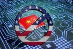
SNPS1670747138 DAC 2025 800x100px HRes

CEVA Accelerates 5G Infrastructure Rollout with Industry’s First Baseband Platform IP for 5G RAN ASICs

CEVA Accelerates 5G Infrastructure Rollout with Industry’s First Baseband Platform IP for 5G RAN ASICs
by Kalar Rajendiran on 10-04-2022 at 6:00 am

PentaG RAN Massive MIMO Radio Platform

The 5G technology market is huge with incredible growth opportunities for various players within the ecosystem. As a leading cellular IP provider, CEVA has been staying on top of the opportunity by offering solutions that enable customers to bring differentiated products to the marketplace. Earlier this year, SemiWiki posted a blog about CEVA’s PentaG2 5G NR IP Platform, the PentaG2 being a follow-on offering to CEVA’s successful first generation PentaG IP Platform. The PentaG2 platform’s target is the 5G user equipment segment of the 5G market and PentaG2 has been enabling customers to develop products rapidly and cost effectively.

But what about the infrastructure segment of the 5G market opportunity? This segment is also huge and lucrative and is attracting a slew of established and new players seeking a slice of the opportunity pie. CEVA recently launched their PentaG-RAN Platform IP to address the infrastructure segment of the 5G market. This industry-first scalable and flexible platform combines powerful DSPs, 5G hardware accelerators and other specialized components required for optimizing modem processing chains. The PentaG-RAN platform also lowers the barriers for entry for new players who want to serve the Open-RAN base station and equipment markets.

If system companies had their druthers, they would implement an ASIC for optimal differentiation of their solutions. Of course, developing an ASIC has gotten challenging in many ways due to design complexities, supply chain disaggregation, costs, availability of technical talent, etc., And, if you are a new player, you may not have in-house seasoned ASIC implementation teams to count on.

What if the PentaG-RAN Platform IP would help overcome the above challenges? Would system companies take the ASIC route and get freedom from the captivity of chipset suppliers? Would chiplet suppliers take advantage of the platform to quickly implement product variants for different segments/customers? What if along with the Platform IP, integration services are available to implement the ASIC? This is the backdrop and context for this blog about the PentaG-RAN announcement from CEVA.

5G RAN Market Opportunity and the Challenge

The infrastructure market covers base stations and radio configurations from small cells to Massive MIMO deployments. According to Gartner, the RAN semiconductor market is expected to grow from $5.5B in 2022 to $7.4B in 2026. Significant Open-RAN architecture penetration is expected around 2025 with Massive MIMO radio being the biggest volume opportunity. New OEMs being attracted by the Open-RAN architecture are desiring to replace cost and power inefficient FPGA-based and COTS platform based implementations. At the same time, they get intimidated just thinking of the ASIC development challenges, given the PHY and radio domains are highly complex to begin with. The scarcity of design and architecture expertise for 5G baseband processing justifiably adds to this apprehension. To top these concerns, the diverse workloads in 5G physical layer require complex and heterogeneous L1 subsystems and optimal hardware/software partitioning.

CEVA’s PentaG-RAN Offering

PentaG-RAN is a heterogeneous baseband compute platform that provides a complete licensable L1 PHY solution with optimal hardware/software partitioning. It addresses the requirements of both the Radio end and the DU/baseband end of the 5G market. The PentaG-RAN platform can also be used as an add-on to COTS CPU-based solutions to run vRAN inline acceleration tasks.

The platform includes high-performance DSPs and 5G hardware accelerators and delivers up to 10x reduction in power and area compared to FPGA and COTS CPU-based alternative solutions.

The Figure below highlights the various CEVA IP blocks that make up a Massive MIMO Beamformer Tile.

The PentaG-RAN platform makes it easier for customers to implement a MIMO beamformer SoC by integrating the included baseband beamformer tile with their own front-haul design.

The Figure below shows how the platform supports the DU end for Small Cell and vRAN designs.

Productivity Tool/Virtual Platform Simulator

As with the PentaG2 platform, the PentaG-RAN deliverables include a System-C simulation environment for architecture definition, modeling, debugging and fast prototyping. The PentaG-RAN SoC simulator supports all CEVA IP and interfaces with MATLAB platform for algorithmic development. A PentaG-RAN based system can also be emulated on a FPGA platform for final verification.

To learn more details, visit the PentaG-RAN product page.

CEVA’s 5G Co-Creation Offering

Through its Intrinsix team, CEVA offers SoC design services for those customers who would like to customize the platform IP to build a highly differentiated SoC. The Intrinsix team is well versed in mapping customer use cases to the PentaG-RAN platform. The team can work on hardware architecture spec, solution dimensioning, interconnect definition, process node selection, and software architecture. In essence, customers can engage CEVA for full-service ASIC engagement from architecture to GDS.

PentaG-RAN Availability

PentaG-RAN will be available for general licensing in 4Q 2022.

Also Read:

5G for IoT Gets Closer

LIDAR-based SLAM, What’s New in Autonomous Navigation

Spatial Audio: Overcoming Its Unique Challenges to Provide A Complete Solution


Micron and Memory – Slamming on brakes after going off the cliff without skidmarks

Micron and Memory – Slamming on brakes after going off the cliff without skidmarks
by Robert Maire on 10-03-2022 at 10:00 am

Wiley Coyote Semiconductor Crash 2022 1

-Micron slams on the brakes of capacity & capex-
-But memory market is already over the cliff without skid marks
-It will likely take at least a year to sop up excess capacity
-Collateral impact on Samsung & others even more important

Micron hitting the brakes after memory market already impacts

Micron capped off an otherwise very good year with what appears to be a very bad outlook for the upcoming year. Micron reported revenues of $6.6B and EPS of $1.45 versus the street of $6.6B and $1.30.

However the outlook for the next quarter , Q1 of 2023….not so much. Guidance of $4.25B +-$250M and EPS of 4 cents plus or minus 10 cents, versus street expectations of $5.6B and EPS of $0.64….a huge miss even after numbers had been already cut.

A good old fashioned down cycle

It looks like we will be having a good old fashioned down cycle in which companies get to at or below break even numbers and cut costs quickly to try and stave off red ink.

At least this is the case in the memory business, which is usually the first to see the down cycle and tends to suffer much more as it is largely a commodity market which results in a race to the bottom between competitors trying to win a bigger piece of a reduced pie.

Will foundries and logic follow memory down the rabbit hole?

While we don’t expect as negative a reaction on the logic side of the semi industry, reduced demand will impact pricing of foundry capacity and bring down lead times. There will certainly be a lot more price pressure on CPUs as competitive pricing will heat up quite a bit. TSMC will likely drop pricing to take back overflow business it let go and we will see second tier foundry players suffer more.
The simple reality is that if manufacturers are buying less memory, they are buying less of other semiconductor types, its just that simple.

Technology versus capacity spending

For many, many years we have said that there are two types of spend in the semiconductor industry. Technology spending, in order to keep pushing down the Moore’s law curve and stay competitive. Capacity spending is usually the larger of the two, obviously mostly in an up cycle, in which the next generation of technology is put into high volume production.

Micron is obviously cutting off all capacity related spend and is just spending on keeping up its lead in technology, which they can never stop given that they are in competition with Samsung.

There is obviously some bricks and mortar spending to build the new fab in Idaho that will continue, but will only be filled with equipment and people when the down cycle in memory is over.

Micron did talk about announcing a second new fab in the US but that is likely to be very far behind the Boise fab announced and may never get built within the 5 year CHIPS for America window. The new Boise fab is 3-5 years away and will likely be on the slow side given the current down cycle.

Capex cut in half – We told you so, 3 months ago.

When you are in a hole, stop digging

We are surprised that everyone, including so called analysts, are shocked about the capex cuts. It doesn’t take Elon Musk (a rocket scientist ) to tell you to stop making more memory when there is a glut and prices have collapsed.
Maybe Micron’s comments about holding product off market last quarter should have been a clue and gotten more peoples attention as a warning sign (it got our attention).

Back when Micron reported their last quarter, 3 months ago we said ” We would not at all be surprised to see next years capex cut down to half or less of 2022’s”

Our June 30th Micron note

In case some readers didn’t get the memo we repeated our prediction of a 50% Micron capex cut a month ago “Micron will likely cut capex in half and Intel has already announced a likely slowing of Ohio and other projects”

Our August 30th note

Semi equipment companies more negatively impacted than Micron

When the semiconductor industry sneezes the equipment companies catch a cold

Obviously cutting Micron’s WFE capex in half is a big deal for the equipment companies as their revenues can drop faster than their customers.

While Micron cutting capex in half is a big deal, Samsung following suit with a capex cut would be a disaster. Its not like it hasn’t happened before ….a few years ago Samsung stopped spending for a few quarters virtually overnight.
We are certain Samsung will slow along with Micron, the only question is how much and do they also slow the foundry side of business.

Could China be the wild card in Memory?

While Micron and Samsung and other long term memory makers have behaved more rationally in recent years and moderated their spend to reduce the cyclicality we are more concerned about new entrants, such as China, that want to gain market share. Its unlikely that they will slow their feverish spending as they are not yet full fledged members of the memory cartel.
This will likely extend the down cycle because even if the established memory makers slow, China will not and will likely extend the glut and extend the down cycle.

Technology will help protect Micron in the down cycle

As long as Micron keeps up its technology spend & R&D spend to stay ahead of the pack or at least with the pack they will be fine in the longer run when we come out of the other side of the down cycle.
Micron has a very long history about being very good spenders and very good at technology and if they keep that up they will be fine. We highly doubt they will do anything stupid.

The stocks

We see no reason to buy Micron any time soon at near current levels.
As we have said recently, we would avoid value traps like the plague.
Semi equipment stocks should see a more negative reaction as they are the ones to see the negative impact of the capex cuts.

Lam , LRCX, is obviously the poster child for the memory industry equipment suppliers and is a big supplier to Micron and more importantly Samsung
We also see no reason to go near Samsung and Samsung may be a short as investors may not fully understand the linkage to the weakness in the memory industry. Semiconductors are the life blood of Samsung and memory is their wheelhouse whereas foundry is their foster child.

We warned people months ago “to buckle up, this could get ugly” and so it continues.

About Semiconductor Advisors LLC
Semiconductor Advisors is an RIA (a Registered Investment Advisor),
specializing in technology companies with particular emphasis on semiconductor and semiconductor equipment companies.
We have been covering the space longer and been involved with more transactions than any other financial professional in the space.
We provide research, consulting and advisory services on strategic and financial matters to both industry participants as well as investors.
We offer expert, intelligent, balanced research and advice. Our opinions are very direct and honest and offer an unbiased view as compared to other sources.

Also Read:

The Semiconductor Cycle Snowballs Down the Food Chain – Gravitational Cognizance

KLAC same triple threat headwinds Supply, Economy & China

LRCX – Great QTR and guide but gathering China storm


WEBINAR: Taking eFPGA Security to the Next Level

WEBINAR: Taking eFPGA Security to the Next Level
by Daniel Nenni on 10-03-2022 at 6:00 am

SemiWiki Flex Logix Intrinsic-ID Webinar

We have written about eFPGA and for six years now and security even longer so it is natural to combine these two very important topics. Last month we covered the partnership between Flex Logix and Intrinsic ID, and the related white paper. Both companies are SemiWiki partners, so we were able to provide more depth and color:

In the joint Flex Logix/Intrinsic ID solution, a cryptographic key derived from a chip-unique root key is used to encrypt and authenticate the bitstream of an eFPGA. If the chip is attacked or found in the field, the bitstream of the eFPGA cannot be altered, read, or copied to another chip. That is because the content is protected by a key that is never stored and therefore is invisible and unclonable by an attacker.

Neither is the concern of counterfeit chips being inserted within the supply chain valid any longer. Each QuiddiKey user can generate an unlimited number of chip-unique keys, enabling each user in the supply chain to derive their own chip-unique keys. Each user can protect their respective secrets as their cryptographic keys will not be known to the manufacturer or other supply-chain users.

To learn even more we have a live webinar coming up where you can interact with the principles:

REGISTER HERE

5G, networking, cloud storage, defense, smart home, automotive, and others – are looking to embedded FPGAs (eFPGA) to save power and reduce cost. All these applications demand reconfigurability with lower power/cost, but they also require strong security.

  • Are you looking to integrate eFPGA into your devices and need a better understanding of how to secure your design?
  • Do you want to understand how to encrypt the eFPGA data, so it is so secure that it is not known to anyone (not even you)?
  • In that case, this is the webinar for you!

This webinar will teach you:

  • The benefits of eFPGA and how it reduces power and cost.
  • H0w to integrate eFPGAs into your design.
  • How to secure an SoC, and specifically how to secure the contents of the eFPGA using SRAM PUF technology.

SRAM PUFs create device-unique keys that are never stored on devices, that cannot be copied from one device to the next, and that are not known to anyone. Use of SRAM PUFs guarantees the data used to program the eFPGA can be trusted and that it cannot be reused on malicious or counterfeit devices, which makes them ideally suited for protecting eFPGAs in security-sensitive markets.

Speakers:

Ralph Grundler is Senior Director of Marketing at Flex Logix, the leading supplier of eFPGA technology. An experienced business development professional, Ralph has a long history in the development and marketing of semiconductors, IP, SoCs, FPGAs, and embedded systems. He has done many videos and live presentations on a wide variety of technical subjects. He has 30 years of computer and semiconductor industry experience.

Vincent van der Leest is Director of Marketing at Intrinsic ID, the leading supplier of security based on SRAM PUF technology. He started at Intrinsic ID 13 years ago working on the research into the company’s core SRAM PUF technology, after which he spent many years in business development and marketing roles when the company started growing.

REGISTER HERE

I hope to see you there!

About Flex Logix
Flex Logix is a reconfigurable computing company providing AI inference and eFPGA solutions based on software, systems and silicon. Its InferX X1 is the industry’s most-efficient AI edge inference accelerator that will bring AI to the masses in high-volume applications by providing much higher inference throughput per dollar and per watt. Flex Logix eFPGA enables volume
FPGA users to integrate the FPGA into their companion SoC resulting in a 5-10x reduction in the cost and power of the FPGA and increasing compute density which is critical for communications, networking, data centers, and others. Flex Logix is headquartered in Mountain View, California and has offices in Austin, Texas and Vancouver, Canada. For more information, visit https://flex-logix.com.

About Intrinsic ID
Intrinsic ID is the world’s leading provider of security IP for embedded systems based on PUF technology. The technology provides an additional level of hardware security utilizing the inherent uniqueness in each and every silicon chip. The IP can be delivered in hardware or software and can be applied easily to almost any chip – from tiny microcontrollers to high-performance FPGAs – and at any stage of a product’s lifecycle. It is used as a hardware root of trust to protect sensitive military and government data and systems, validate payment systems, secure connectivity, and authenticate sensors. For more information, visit https://www.intrinsic-id.com/.


Super Cruise Saves OnStar, Industry

Super Cruise Saves OnStar, Industry
by Roger C. Lanctot on 10-02-2022 at 6:00 pm

Super Cruise Saves OnStar Industry

Listen in on any automotive podcast, earnings call, or attend any automotive industry event and you will hear about “software defined” cars and “service oriented architectures.” This euphemistic terminology obscures the reality that cars in most major markets are almost universally connected – even if the owners of those cars are not fully invested in the concept of “connectivity.”

The automotive industry is still languishing in a subscription adjacent mindset with a customer base that remains largely skeptical of subscription-based models. By and large, consumers want to pay a single price for their automobiles and don’t yet fully perceive the need to pay a separate fee for vehicle connectivity.

This is not to say that all new car buyers and owners refuse to pay the $10-$30/month for a typical telematics service package. Many do – enough, in fact, to make connectivity platforms reasonably profitable or minimally loss-inducing.

What the industry needs, though, is a transformation. General Motors, the originator of OnStar vehicle connectivity a quarter century ago, is pointing the way.

Traditional telematics services such as automatic crash notification, stolen vehicle tracking and recovery, and remote diagnostics seem to have faded in importance. Intrusion detection and over-the-air software updates, meanwhile, have not yet captured consumers’ imaginations.

What has caught the attention of consumers is GM’s Super Cruise semi-automated driving solution. Already embedded in 40,000 GM vehicles currently in circulation, Super Cruise is slated for deployment in 22 GM car models by the end of 2023.

The key to Super Cruise’s industry impact is that it requires an OnStar subscription. If consumers want access to GM’s sexiest driving enhancement in the history of the company, they will have to pay a monthly fee.

It doesn’t matter that the fee covers the expense of connectivity necessary for enhancing situational awareness and positioning accuracy. It doesn’t matter that there are multiple layers of enabling technology providing redundancy and ensuring reliability.

The Super Cruise user can take their hands off the wheel as long as they are paying attention to the driving task. In fact, the driver monitoring system opens the door to driver identification and credentialling which can be used to support and enhance other connected driving tasks – and access to services.

Super Cruise is the long sought after “killer app” that is already changing the perception of vehicle connectivity. Super Cruise is a gateway to the broader deployment, adoption, and acceptance of software updates. Super Cruise gives car connectivity a reason to exist.

Dealers now have a story they can tell around car connectivity that makes sense to the customer. In fact, dealers have a powerful motivation to demonstrate the technology in action and ensure that the new car buyer is properly provisioned with cellular service before they leave the lot.

Four years into the launch of Super Cruise, GM has yet to experience a high profile failure of the technology in operation. And unlike Tesla’s Autopilot and Full-Self-Driving beta, there is no flood of Youtube videos highlighting its shortcomings.

(I will note here that Tesla’s $10/month connectivity is itself clearly subsidized and discounted due to the value Tesla is extracting from the data it is gleaning from its connected cars – hundreds of millions of dollars in value. Competing auto makers can be expected – or should be expected – to recognize a similarly discounted connectivity proposition.)

There have been no National Highway Traffic Safety Administration investigations of Super Cruise. And there have been no fatal crashes reported.

Most telling of all, though, is the fact that GM has begun advertising Super Cruise. Super Cruise is rapidly becoming a brand-defining application with broad consumer appeal and growing consumer awareness.

In sum, Super Cruise has come to rescue of OnStar’s original mission of promoting the concept of vehicle connectivity. Super Cruise has single-handedly solved the business model of subscription-based vehicle ownership and sped the adoption of over-the-air software updates.

Also Read:

Arm and Arteris Partner on Automotive

The Truly Terrifying Truth about Tesla

GM Should BrightDrop-Kick Cruise

Ultra-efficient heterogeneous SoCs for Level 5 self-driving


Podcast EP109: The State of Semiconductors and the Supply Chain with PWC

Podcast EP109: The State of Semiconductors and the Supply Chain with PWC
by Daniel Nenni on 09-30-2022 at 10:00 am

Dan is joined by Scott Almassy, a Partner in PwC’s Trust Solutions business, as well as PwC’s Semiconductor and Infrastructure Lead. In his almost 20 years in the professional services industry, Scott has provided audit and advisory services to semiconductor companies across the industry ranging from the largest multinationals to the smallest startups.

Dan and Scott discuss the state of the semiconductor industry and the associated worldwide supply chain. Current health and future challenges are discussed as well as the impact of the CHIPS Act.

The views, thoughts, and opinions expressed in these podcasts belong solely to the speaker, and not to the speaker’s employer, organization, committee or any other group or individual.


Moore’s Law is Dead – Long-live the Chiplet!

Moore’s Law is Dead – Long-live the Chiplet!
by Paul McWilliams on 09-30-2022 at 8:00 am

Moores Law Slows

Dr. Gordon Moore was the Director of Research and Development at Fairchild when he wrote the paper, “Cramming More Components onto Integrated Circuits” that was published in the April 19, 1965 issue of Electronics.  Following this publication, Dr. Carver Mead of Caltech declared Dr. Moore’s predictions as “Moore’s Law”.

Very few people understand the essence of Moore’s Law or know about the myriad of tangential projections Dr. Moore made in this relatively short paper; these included home computers, automatic controls for automobiles, personal portable communications equipment and many other innovations that at the time may have seemed like science fiction to some readers.

Among Dr. Moore’s projections for Integrated Circuits (ICs) was that by 1975 economics may dictate squeezing as many as 65,000 components on a single silicon chip.”  It took a couple years longer than the projection, but the first 64Kb DRAM (Dynamic Random Access Memory) was released in 1977 with 65,536 transistors on a “single silicon chip.”  That is a remarkable projection since the first commercially viable DRAM was introduced in 1970; five years after Dr. Moore’s paper was published.

The essence of Moore’s Law

While there are a number of projections included in Moore’s Law and virtually all of them panned out to a reasonable degree, there are two projections that are the “essence” of Moore’s Law.  If we do a little math, we can add some color to these projections.  Below are two quotes from the original 1965 article and my extrapolation of the predictions.

  • “The complexity for minimum component costs has increased at a rate of roughly a factor of two per year. Certainly over the short term this rate can be expected to continue, if not to increase. Over the longer term, the rate of increase is a bit more uncertain, although there is no reason to believe it will not remain nearly constant for at least 10 years.”  This suggests that over the next ten years, we will see transistor (component) density increase by a factor of approximately 1,024.
  • “In 1970, the manufacturing cost per component can be expected to be only a tenth of the present cost.” This projects that while transistor (component) density will double every year, the cost per component will decrease at a rate of about 37% per year.  This is important to understand, so let’s take a moment to run through the math.  With each doubling of component density there are higher manufacturing costs, but Dr. Moore correctly projects these higher costs will be far more than offset by the annual doubling of density.  The result is a net compounded cost reduction of 37% per transistor (component) that results in a 90% cost decrease in five years and a 99% cost decrease in ten years.

Following this ten-year run to 1975, which worked out very similar in most ways to the projections of Moore’s Law, Dr. Moore reset forward expectations to a doubling of transistor density every 18 to 24 months versus every year.  As a result of this remarkable progress, if you live at or above the middle class in a developed nation, there is a very good chance you are a “transistor trillionaire” – that with all the electronic stuff you own, you have over a trillion transistors.

How Far Have We Come – A case study

When I entered the semiconductor industry in 1976, the dominant DRAM device was the 16Kb (16K x 1) Mostek MK41161 (Intel had the 2116, but Mostek was the leading provider).  Its power consumption (active state) was approximately 0.432 Watts (432mW).  Due to the large package sizes used in 1976, you could only fit about 1.5 devices per square inch of printed circuit board (PCB) area.  As best as I can recall, the MK4116 sold for about $10 (1976 dollars) in production volume.

(1) While the 64Kb DRAM was released in 1977, its cost per bit remained higher than the 16Kb DRAM until about 1980.

If we extrapolate these data we can see that the typical 16GB (16Gb x 8) memory used in consumer PCs today would cost about $80 million just for the memory chips ($400 million in 2021 dollars), require a PCB that is about 37,000 square feet in size (larger than the 35,000 square foot concourse at Grand Central Station) and would consume about 3,500,000 Watts of electricity.  At $0.10 per KWh it would cost over $250,000 per month to power this memory board.2

(2) To keep things simple, all the calculations are based on only the 8,000,000 MK4116 DRAMs that would be required to deliver 16GB of memory. In addition these, a myriad of additional passive and active components would also be required.  These components are not included in any of the calculations.

Today, you can buy a 16GB DRAM module for a laptop PC in a retail store for about $40 (about $8 1975 dollars) that is about the size of your index finger and consumes less than 3 Watts of power.  This is easily powered from a laptop PC battery, but at $0.10 per KWh, the monthly cost would be a little over $0.20.

Obviously, from so many perspectives (cost, thermal, size and reliability to name a few) it would have not only been impractical, but literally impossible to build a 16GB DRAM memory board in 1976.  Of course, it wouldn’t have been useful anyway – the microprocessors available in 1976 could only address 64KB of memory.  However, this illustration of the advances driven by Moore’s Law since I joined the industry is simply a case study illustration of how far the industry has come.

If we adjust for inflation, our data tell us the advancements predicted by Moore’s Law have led a 99.9999995% reduction in cost (that is 30% compounded annually for 45 years) and a 99.9999993% reduction in power consumption.  And, when you combine these advancements with an even greater reduction in the area required, you can better appreciate what Moore’s Law has not only made possible, but much more importantly, practical and affordable.

While it’s fairly straightforward to extrapolate the advancements in semiconductor fabrication have driven the cost per bit of DRAM down by a factor of about 10 million, it’s much more tedious to estimate the improvement for processors.  Industry luminaries who are much smarter than me have stated that when you consider the advancements in compute architecture that have been enabled by Moore’s Law, the economic efficiency of processor ICs has improved by a factor greater than one billion since the introduction of the 4004 in 1971.

While it is hard to visualize and quantify these improvements with numbers, it is very easy to substantiate that even an average smartphone today has FAR more computing power than all of NASA did when the Apollo 11 mission landed astronauts on the moon in 1969.  Think about that the next time you ask Siri, Alexa or Google a question…

Transistor Economics

There are all sorts of fancy words you can use to describe various business models, but I like to keep things as simple as possible.  Within any business model, you can divide the costs between “fixed” (capital) and “variable” (marginal).  If the model is heavily weighted to variable expenses, there is little scaling (leverage) and profitability runs a fairly linear line with volume.  However, if the model is heavily weighted to fixed costs, the model scales (often dramatically) and profitability increases steeply as volume grows.

For example, if you were going to drill for oil, you would have to build a rig and make all the associated capital investments needed to drill for oil (fixed costs), but once it is built and the oil starts to flow, the costs to maintain that flow (variable costs) are very low.  In this business model, the high fixed costs are amortized across the barrels of oil that are pumped.  The obvious conclusion is the more barrels of oil that are produced, the lower the total cost per barrel (fixed costs are amortized across more barrels of oil).

The somewhat less obvious conclusion is the “marginal cost” of the “next” barrel produced is very low.  Since marginal (variable) cost represents the total cost increase to produce one more unit (barrel) and there are no additional fixed costs required, only the variable costs are counted.  Obviously, given these data, volume is VERY important in business models that operate with high fixed and low variable costs.

This classic example of a high fixed / low variable cost business model is more or less aligned with what we see in the classic semiconductor business model.  It costs an enormous amount of money to open a leading edge semiconductor fabrication line (measured in tens of billions of dollars today) and designing a relatively complex IC for a leading edge fabrication process (5nm) could easily cost a half a billion.  However, once the fabrication plant is operational and the IC is in production, the marginal cost for fabricating the next silicon wafer is small relative to these fixed costs.

The semiconductor industry has one huge advantage over the oil industry; unlike oil where there are limitations to the ultimate supply (discovered reserves), there is a virtually endless supply of relatively cheap silicon (the base material for most semiconductor wafers), which means there are solid reasons to continuously drive prices lower to stimulate more demand, and produce more volume.

This phenomenon is demonstrated in the data.  Bell Labs produced exactly one transistor in its lab in 1947 and it would take several years beyond that before a handful were produced for limited applications.  In 2022, only 75 years later, the semiconductor industry will produce literally hundreds of billions if not trillions of transistors for every man, woman and child on earth and sell them in the form of ICs for infinitesimal fractions of a penny.

There are probably a number of stories behind how this amazing growth trend was launched, but one of my favorites was told by George Gilder in his book, Microcosm.

As the story was related by George, Fairchild Semiconductor was selling a transistor (part number 1211) in relatively small volumes to military customers for $150 each.  With a cost of roughly $100, Fairchild made a nice profit.  However, given the stringent military specifications, it was left with scrap parts that didn’t meet the customer requirements.

To find a home for these transistors, Jerry Sanders3, who had been recently promoted to run Fairchild’s consumer marketing group, was tasked to find a buyer willing to pay $5 for the rejects.  He found some willing buyers, but in 1963, when the FCC mandated that all new televisions include UHF reception, a huge new market opportunity opened.

(3) Jerry Sanders later left Fairchild to start Advanced Micro Devices (AMD)

The problem here was that at even $5, the consumer version of the 1211 could not compete with RCA’s innovative metal cased vacuum tube called the Nuvistor that it was offering to TV manufacturers for only $1.05.  Sanders tried every angle he could to get around the $3.95 price difference – the consumer 1211 could be soldered directly to the PCB avoiding the use of a socket for the Nuvistor and the transistor was clearly more reliable.  However, he simply couldn’t close the deal.

Given the market potential for TVs in 1963 was approximately 10 million units per year; Sanders went to Fairchild headquarters in Mountain View and met with Dr. Robert Noyce at his home in the Los Altos hills.  He was hesitant at first to ask for the $1.05 price he needed to close the deal, but once Sanders described the opportunity, Dr. Noyce took the request in stride and after brief contemplation, approved it.

Sanders returned to Zenith and booked the first consumer 1211 order for $1.05.  To drive down costs, Fairchild opened its first overseas plant in Hong Kong that was designed to handle the anticipated volume and in conjunction with that developed its first plastic package for the order (TO-92).  Prior to this, all 1211s were packaged as most transistors were at the time, in a hermitically sealed (glass to metal sealed) metal can (TO-5).

Once Fairchild had production dialed in, it was able to drop the price to $0.50, and within two years (in 1965) it realized 90% market share for UHF tuners and the new plastic 1211 generated 10% of the company’s total profit.  1965 happened to also be the year that Dr. Moore wrote the article that was later deemed “Moore’s Law.”

The lesson from the 1211 transistor about how to effectively leverage low marginal costs to drive volume was tangential to Dr. Moore’s paper.  However, when coupled with the prophesy of Moore’s Law that correctly predicted the cost per transistor on an IC would fall rapidly as fabrication technology advanced, the mold for the semiconductor business model was cast and capital flowed freely into the industry.

The March of Moore’s Law in Processors:

In 1968, three years after “Moore’s Law” was published, Dr. Moore and Dr. Noyce, who is credited for inventing the planar Integrated Circuit (IC) in 1959, left Fairchild to start Intel (INTC).  They were soon joined by Dr. Andy Grove, who with his chemical engineering background ran fabrication operations at Intel.  Following Dr. Noyce and Dr. Moore, Dr. Grove was named as Intel’s third CEO in 1987.

Intel started out manufacturing Static Random Access Memory (SRAM) devices for mainframe computers (semiconductor memories were a part of Moore’s Law predictions), but quickly developed ICs for watches and calculators, and moved from there to general purpose processors.  In an effort to optimize continuity, I’ll focus mostly on the evolution of Intel processors in this section.

Intel’s first processor, the 4-bit 4004, was released in 1971.  It was manufactured using 10,000nm fabrication technology and had 2,250 transistors on a 12mm2 die (187.5 transistors per mm2).  Intel followed this a year later with its first 8-bit processor, the 8008.  It used the same process technology as the 4004, but with better place and route, it had 3,500 transistors on a 14mm2 die (250 transistors per mm2).

Intel released its first 16-bit processor, the 8086 in 1978, which introduced the world to the x86 architecture that continues to dominate personal computing and data center applications today.

A year later, Intel released the 8088, which was virtually identical to the 8086, but used an external 8-bit data bus, which made it much more cost-effective to use in the first IBM PC.  Both the 8086 and 8088 were fabricated using a 3,000nm process and both had 29,000 transistors on a 33mm2 die (879 transistors per mm2).  What’s not widely known or appreciated is the 8086 and 8088 developed such a vast design base outside the PC market that Intel manufactured both ICs until 1998.

Intel released the 32-bit 80386 in 1985, which was fabricated using a 1,500nm process and with 275,000 transistors and a 104mm2 die size (2,644 transistors per mm2), it far surpassed everything that came before.  This marks the first time I remember reading a Wall Street prediction that Moore’s Law is dead.  It was several years later when I realized Wall Street opinions about the semiconductor industry were almost always wrong, but that goes into another story for another time…

As Intel’s current CEO, Patrick (Pat) Gelsinger covers in this linked article:  “Pat Gelsinger Takes us on a Trip Down Memory Lane – and a Look Ahead”.

As the years passed, the cadence of Moore’s Law continued; running more efficiently sometimes than others, but with consistency when viewed over the longer term.  To make it a little easier to track the progress of Moore’s Law, the following table displays PC processors fabricated on the various processes from 1,000nm to 14nm from 1989 through 2015.  Since I don’t have a reliable source for data beyond 14nm for Intel, I stopped there.

Processor Year Fabrication Process Die Size Transistor Count Transistors per mm2
80486 1989 1,000nm 173mm2 1.2 million 6,822
Pentium 1993 800nm 294mm2 3.1 million 10,544
Pentium Pro 1995 500nm 307mm2 5.5 million 17,915
Pentium II 1997 350nm 195mm2 7.5 million 38,462
Pentium III 1999 250nm 128mm2 9.5 million 74,219
Pentium IV Willamette 2000 180nm 217mm2 42 million 193,548
Pentium IV Northwood 2002 130nm 145mm2 55 million 379,310
Pentium IV Prescott 2004 90nm 110mm2 112 million 1,018,182
Pentium C Cedar Mill 2006 65nm 90mm2 184 million 2,044,444
Core i7 2008 45nm 263mm2 731 million 3,007,760
Core i7 Quad + GPU 2011 32nm 216mm2 1,160 million 5,370,370
Core i7 Ivy Bridge 2012 22nm 160mm2 1,400 million 8,750,000
Core i7 Broadwell 2015 14nm 133mm2 1,900 million 14,285,714

This table and the data above it, illustrates Intel increased transistor density (transistors per mm2) by an amazing factor of 76,190 in the 44-year span from its first processor (4004) to its Core i7 Broadwell.

When we consider server ICs (as opposed to just PC processors in the table above), we can see significantly higher transistor counts as well as substantially larger die sizes.

Intel released its first 2 billion transistor processor, the 64-bit Quad-core Itanium Tukwilla in 2010 using its 65nm process.  With the large cache memories, the die size was 699mm2 (2.86 million transistors per mm2).

Intel went on to break the 5 billion transistor barrier in 2012 with the special purpose Xeon Phi.  It was fabricated using a 22nm process on a massive 720mm2 die (6.9 million transistors per mm2).  This is the largest die size I can find for an Intel processor.

The Xeon Phi is one of only three monolithic processors I’ve found that used a die size larger than 700mm2.  The other two are the Fujitsu SPARC VII fabricated on a 20nm process4 in 2017, which used a massive 795mm2 die (6.9 million transistors per mm2), and the AMD (AMD) Epyc fabricated on a 14nm process using a slightly smaller 768mm2 die, but with the smaller fabrication process, it had much higher transistor density (25 million transistors per mm2).  The Oracle (ORCL) SPARC M7 was probably larger than the Fujitsu SPARC VII, but I could not find die size data for the Oracle processor.

Intel has a long history of more conservatively stating its fabrication process nodes, which explains why its transistor density at 22nm is approximately the same as Fujitsu’s was for its 20nm SPARC processor.

While the days of microprocessor die approaching the size of a postage stamp are gone, advances in fabrication technology continue to enable higher and higher transistor density.  The highest density I can quantify today for a processor is the Apple (AAPL) M1-Max that has 57 billion transistors on its 432mm2 die (131.9 million transistors per mm2) and is fabricated using TSMC (TSM) 5nm technology.

The transistor density of the Apple M1-Max is over 700,000 times greater than Intel’s first 4004 processor, and from a technical perspective, that tells us the Moore’s Law prediction of doubling transistor density is still alive; albeit at a slower pace than it once was.  However, while transistor density will continue to increase, two things have happened during recent advancements of fabrication technology that are important to understand.

First, my contacts tell me the curve of lower and lower cost per transistor that has been the economic driver for Moore’s Law for over 50 years began flattening after the 10nm fabrication node. This means the days of cheaper transistors offsetting the rapidly increasing fixed costs to design and get a new IC into production are at least numbered if not gone.  This means if the primary economic driver of Moore’s Law isn’t dead, it’s on life-support.

Second, the data tell us that processor manufacturers have moved away from the massive die sizes introduced between 2012 and 2017 and even leading processor manufacturers like AMD and Intel have adopted Chiplet strategies. In the case of the Intel Ponte Vecchio, the design includes 47 Chiplets using a variety of fabrication technologies.

Intel:  Meteor Lake Chiplet SoC Up and Running

Intel Xeon Sapphire Rapids:  How To Go Monolithic with Tiles [Chiplets]

Intel Ponte Vecchio and Xe HPC Architecture: Built for Big Data

AMD ON WHY CHIPLETS—AND WHY NOW

The king is dead, long live the king!

Defect Density (D0) for a given fabrication process is defined as the number of defects per silicon wafer, divided by the area of the wafer, that are large enough to be classified as “killer” defects for the targeted fabrication process.  The problem is, as the fabrication process (fabrication node) size shrinks so does the size of what is determined to be a “killer” defect.

In general, a killer defect is defined as a defect that is 20% the size of the fabrication node.  For example, a defect that is less than 9nm may be acceptable for the 45nm fabrication node, but a defect larger than 2.8nm would be defined as a “killer” defect for the 14nm fabrication node.  For the 5nm fabrication node, a defect measuring only 1nm could be a killer.

This is one of the primary reasons that it has become increasingly difficult to yield large monolithic ICs (as measured in die area) when using leading edge fabrication process technology5.  We can see evidence of this in the data above that shows die sizes for processors peaked during the six year span running from 2012 to 2017 when the state of the art was moving from 22nm to 14nm.

Memory devices, FPGAs, GPUs and some specialized Machine Learning (ML) ICs are subject to the same yield challenges. However, in these ICs you’ll find billions of identical cells (function blocks) that are literally identical to one another. To optimize yields, these ICs that still use monstrous die sizes are commonly designed with redundant cells that can be either masked or programmed to replace cells that don’t yield.  It is unclear if this trend will continue.

There are a variety of opinions as to when Defect Density became an insurmountable issue.  However, from what I’ve read, it appears to have entered the equation in the 22nm to 14nm window, and below 14nm the data suggest it became significant, and looking beyond that, a problem that would only get worse.

Given the fact a large die size IC is more likely to have a defect within its borders than a small die size; there is an inverse correlation between die size and yield, and the trend will become even more vexing as fabrication technology advances to smaller and smaller nodes.

This problem was highlighted by TSMC during Q2 2020 when it was running test wafers for its new 5nm fabrication node.  Following these tests, TSMC stated its average yield for an 18mm2 die was ~80%, but that yield dropped dramatically to only 32% for a 100mm2 die. As has been the case throughout the reign of Moore’s Law, TSM has improved its yield since these early tests, but in spite of that, I’m sure the yield at 5nm remains less favorable than the yield at larger fabrication nodes and the trend going forward is clear; the era of large monolithic die has passed.

Several years before TSMC released early data on its 5nm process, AMD CEO, Dr. Lisa Su presented the Defect Density problem in a very simple graph at the 2017 IEEE International Electron Devices Meeting (IDEM).  This graph shows the increase in cost per yielded mm2 for a 250mm2 die size as AMD moved forward from 45nm to smaller fabrication nodes.  The understated conclusion is increasing die sizes become economically problematic, and once you go below 14/16nm, the yielded cost increases dramatically.

Defect Density is not a new problem – it has literally existed since day one.  However, lessons learned have always pushed it forward beyond the current fabrication node and the ability to cure yield problems at the current node is what drove Moore’s Law for over 50 years.  While you can rest assured there are continued efforts to reduce the impact of Defect Density at leading edge fabrication nodes, there are five reasons that suggest the Chiplet trend is not only here to stay, but that it is also poised to expand rapidly and enable new market opportunities.

(1) There have been very significant investments in Chiplets to reduce assembly costs and optimize performance. While there are inherent cost and performance penalties when you move a design away from a single-chip monolithic piece of silicon, it appears performance penalties will be minimized and cost penalties will be more than offset as Chiplet technology is fully leveraged.

(2) The Universal Chiplet Interconnect Express (UCIe) consortium has specified a die-to-die interconnect standard to establish an open Chiplet ecosystem. The charter members of the consortium include:  ASE, AMD, Arm, Google Cloud, Intel, Meta, Microsoft, Qualcomm, Samsung, and TSMC.  UCIe is similar to the PCIe specification that standardized computing interfaces.  However, UCIe offers up to 100 times more bandwidth, 10 times lower latency and 10 times better power efficiency than PCIe.  With this standard in place, I believe we’ll see a flood of new Chiplets come to market.

(3) With the release of its Common Heterogeneous Integration and Intellectual Property Reuse Strategies (CHIPS) program in 2017, the Defense Advanced Research Projects Agency (DARPA) was ahead of the Chiplet curve. The goal for CHIPS is to develop a large catalog of third party Chiplets for commercial and military applications that DARPA forecasts will lead to a 70% reduction in cost and turn-around time for new designs.  The DARPA CHIPS program extends beyond leveraging the benefits of incorporating heterogeneous fabrication nodes to also incorporating heterogeneous materials in a Chiplet design.

(4) The magic of Moore’s Law was that the fabrication cost per transistor would decline far more than fixed costs increased as fabrication technology advanced. I can’t find data to quantify this, but I can find wide agreement that the declining fabrication cost curve flattened around 10nm and that it is heading in an unfavorable direction.  Since advanced fabrication costs are increasing, a Chiplet strategy enables IC architects to target leading edge (expensive) fabrication nodes only for the portions of Chiplet designs that absolutely need the highest possible performance and target other portions of Chiplet designs to fabrication processes that are optimized for low power and/or low cost.

(5) Chiplet designs can accelerate time to market, lower fixed costs, lower aggregate fabrication costs for a given design and leverage architectures that can be extended and/or changed over time. In other words, Chiplet designs provide unique flexibilities that are not economically viable in monolithic designs.  This trend will become more apparent and accelerate as we see new UCIe-compliant Chiplets introduced.

Not only are manufacturers facing a Defect Density yield challenge that has a direct correlation with die size, as you can see from the following graph, the fixed costs associated with designing and moving a new complex monolithic IC into production have skyrocketed along with advances in fabrication technology.  In other words, the data suggest we have hit a tipping point and Chiplet is the answer; not only to the challenges of yield and higher costs, but also enable the semiconductor industry to open new market opportunities.

While my focus in this paper has been on processor ICs (mostly Intel processors for the sake of continuity), increasing fixed costs and the inverse correlation between yields and die size are impacting System on a Chip (SoC) designs too.  There is already evidence that MediaTek will move to a Chiplet design at 3nm with TSMC for its smartphone Applications Processor (AP) and my bet is Qualcomm has a Chiplet design brewing that it has yet to make public.

With UCIe standardization and the DARPA CHIPS program, SoC manufacturers that target the vast array of markets beyond smartphone APs will adopt Chiplet designs to lower costs, shorten development cycles and increase flexibility.  This will open new opportunities for support chip manufacturers and a wide variety of IP companies.

I believe we will also see IP companies expand their traditional market approach by leveraging the new UCIe specification to “harden” their IP into known good die (KGD) and effectively sell their IP as a hardware Chiplet directly to semiconductor manufacturers and IC fabrication companies as well as OEM customers that develop their own Application Specific Chiplet.

One of the more interesting things that I think Chiplets will enable is SoCs for new markets that don’t have the volume or are too fragmented to drive a several hundred million dollar investment in a monolithic IC design.  These include a wide variety of IoT, AI and Machine Learning (ML) opportunities where FPGA technology that can be used for accelerators that can quickly adapt to changing algorithms and provide the design flexibility needed to extend market reach and SoC lifecycle.

Chiplets can also enable SoC solutions for new and existing markets by providing scalable processor solutions and other customer specific options (add more processor cores, add an accelerator, add more memory, even change / update the RF section for a new standard, etc.).  These sorts of changes and flexibilities were virtually impossible with monolithic IC designs.

Bottom Line: Without the benefit of declining variable costs (lower fabrication costs per transistor) offsetting sharply higher fixed costs and the increased complications of Defect Density, Moore’s Law is over as we’ve known it.  However, as it has in the past, the semiconductor ecosystem is adapting and as Chiplet technology builds traction, we will very likely see a period of accelerating innovation and new market opportunities opening as we move forward.

The point here (tipping point if you will) is that Chiplets open new doors for creativity and the continued broadening of technology in how we live and work.  We have reached a point where we no longer need to think only about what makes sense for monolithic IC designs that are hindered with ultra-high fixed costs and painfully long lead times; we can now focus on heterogeneous Chiplets that leverage new open standards to optimize designs for the ultimate cost and performance dictated by the use case.

When you couple these new benefits with the standardization of UCIe and the DARPA CHIPS program, there is great potential to open new markets and new use cases that have yet to even see the back of a cocktail napkin.

Also Read:

UCIe Specification Streamlines Multi-Die System Design with Chiplets

Ansys’ Emergence as a Tier 1 EDA Player— and What That Means for 3D-IC

Five Key Workflows For 3D IC Packaging Success


CEO Interview: Coby Hanoch of Weebit Nano

CEO Interview: Coby Hanoch of Weebit Nano
by Daniel Nenni on 09-30-2022 at 6:00 am

Weebit Nano Coby Hanoch Smaller2

Coby Hanoch comes to Weebit Nano with 15 years’ experience in engineering and engineering management and 26 years’ experience in sales management and executive roles. Coby was Vice President Worldwide Sales at Verisity where he was part of the founding team and grew the company to over $100M in annual sales which facilitated its acquisition by Cadence Design Systems (NASDAQ:CDNS). He was also Vice President Worldwide Sales at Jasper, doubling sales before it was acquired by Cadence. Coby was brought in as CEO to help PacketLight avoid bankruptcy and get it back to a leadership position in its domain. Prior to Weebit, Coby set up his own consulting company, EDAcon Partners, helping startups define their corporate strategies, to set up their worldwide sales channel and raise capital.

What is Weebit Nano’s backstory?
Weebit Nano delivers the industry’s most advanced memory technologies to help semiconductor companies and foundries easily and cost-effectively differentiate their products. We’re bringing to market a new type of non-volatile memory (NVM) called ReRAM (Resistive Random Access Memory) which will be the successor to flash memory for the many applications that need better performance, reliability, power consumption and cost.

Weebit was founded in 2015 and is headquartered in Israel, with R&D teams in Israel and France. Our R&D partner, CEA-Leti, is one of the world’s most advanced microelectronics research institutes, and together we’ve created a truly innovative NVM technology based on over a decade of research.

Weebit is focused on creating advanced technologies that are also economically viable. Even the most cutting-edge technology won’t succeed if it isn’t affordable and easy for customers to integrate and manufacture. Our focus on both innovation and commercial success comes from the deep experience of our executive team and Board. Even just looking at four key people – our Chairman Dadi Perlmutter, Directors Atiq Raza and Yoav Nissan Cohen and myself, together we have over 150 years of combined industry experience with companies including AMD, Intel, National Semi, Tower Semi, Cadence, and others. A similar depth of experience is found across the company.

Weebit is a public company listed on the Australian Stock Exchange (ASX:WBT). Being publicly listed is a great way to accelerate technology development since it gives us immediate access to the financial markets when fund raising is needed, and it also provides transparency that translates to customer and partner confidence.

What makes Weebit ReRAM unique?
Today, flash is the most common NVM, and while it has done a great job to-date, flash has limits in terms of speed, power, cost and endurance. As an embedded technology, it also can’t scale to the most advanced process nodes with the rest of a chip. So, for these and other reasons, the industry needs a new NVM. Of course, it has to be a technology that doesn’t require heavy investments and also one that can use existing manufacturing techniques.

Weebit ReRAM can scale well below 28nm, and it has much faster memory access time and higher endurance than flash, as well as lower power consumption and operating voltage. It can also maintain data at high temperatures for many years, a requirement of many companies we’re talking to. Our ReRAM is also based on the most common materials used in fabs, and uses standard tools and processes, so it can be easily integrated into any standard CMOS flow. It needs only two additional masks, versus around 10 for flash, so added wafer cost is minimal.

ReRAM is also a back-end-of-line (BEOL) technology, an advantage over flash which is a front-end-of line (FEOL) technology that often requires designers to make compromises with analog components and devices. ReRAM doesn’t have this problem, and you can also adapt ReRAM once for a technology node and it works for all its variants.

So that’s all compared to flash, but Weebit ReRAM also wins on almost every parameter compared to other emerging NVMs like MRAM. This is true on tech specs, and more importantly when you look at the simplicity of our technology and how easy it is to integrate into existing processes, translating to lower cost and lower risk.

What market segments are you targeting?
Nearly every electronic device in the world is a potential target for our ReRAM. Digital products that wake up, run code, sense the environment, process and store data need NVM. Adoption timelines in different applications vary, due both to end market requirements and ReRAM’s rollout, which is starting in small densities. Our first offering will be ReRAM IP that customers will embed in their designs. Discrete chips will come later.

Embedded applications for ReRAM are fairly endless and span different process nodes, memory sizes and usage profiles. There are short-term opportunities in areas like power management ICs and other analog designs where BEOL NVM technology is a true advantage, and in areas like IoT and MCUs where ReRAM checks all the boxes for low power, low cost, a high level of integration, plus endurance in harsh conditions. Over time, we’ll see ReRAM in areas like edge AI, industrial and automotive, and there are longer-term opportunities in neuromorphic computing, where the properties of ReRAM mean it can efficiently emulate neural networks in an analog way, versus the simulations you see today.

What keeps your customers up at night?
Weebit’s customers are fabs and semiconductor companies. Obviously concerns vary, but we know they are looking to deliver designs to spec, on time, and on quality. They are also focused on innovating with technologies that help them differentiate against their competition, while maintaining a competitive price.

As companies look beyond 28nm, scaling challenges for embedded NVM become a real concern. For other designs, it could be the cost of NVM process integration, for example in analog and power flows. Flash is expensive and complicates the design, while forcing design constraints. Of course, power is always a concern, where ReRAM demonstrates an order of magnitude improvement over flash. The list of specific design concerns is long, and ReRAM can help customers solve such challenges.

Of course, selecting a new technology like ReRAM is a strategic decision because customers need to know the IP works. This is where our qualification results are key. We’re already sharing initial results, and potential customers are extremely impressed with what they’re seeing. As we continue towards production and deliver final results, it will give customers the level of confidence they need to integrate Weebit ReRAM into their designs.

On a personal note, what was your path to joining Weebit?
I joined Weebit as CEO in 2017 after spending almost 40 years with global EDA, IP and semiconductor companies, in CEO and founder roles as well as engineering and sales positions. At the time, I had been in discussions with Weebit’s chairman Dadi Perlmutter about a Board position and then, when the previous CEO asked to step down for personal reasons, he asked me to become CEO.

Since joining Weebit, my goal has been to focus our efforts and drive meticulously toward mass production. This meant making the early decision to first concentrate on developing IP solutions for the embedded market, and also focus on standard materials and processes. This doesn’t mean we aren’t continuing our efforts toward discrete products – we are actually making good progress in that area – but the main effort is on completing successive milestones towards a commercial IP solution. If you look back over the last several years, you can see we’re doing just that.

What’s next for Weebit Nano?
Weebit is making great strides toward commercialization. Currently, we are qualifying our ReRAM module with CEA-Leti, and while Leti isn’t a production fab, they have a very advanced R&D fab, so the results are significant. We expect to complete that full qualification before the end of the year. We’ve also finished technology transfer to SkyWater Technology, which is the first time we’ve transferred to a production fab, and we expect those wafers back before the end of the year. We’ll then begin that qualification, with expected results in early 2023. We have many other initiatives underway, including making Weebit ReRAM available in 22nm FD-SOI.

This is all pushing Weebit embedded ReRAM technology toward mass production. As I mentioned, we’re also working toward a mid-term goal of discrete ReRAM chips where the key is novel selector technology, and we’re making solid progress together with Leti.

I am highly confident that 2023 will be a banner year for Weebit. The focus, flexibility and excellence the Weebit team exhibited throughout the pandemic – meeting and in some cases exceeding development milestones – was impressive. This sets the stage for continued stellar execution, and we couldn’t be more excited about the opportunities in front of us.

How do customers engage with you?
We are already in discussions with multiple semiconductor companies and fabs that want to get an early advantage with Weebit ReRAM IP, and of course we’d love to engage with other forward-thinking companies. Contact info@weebit-nano.com to get started! SkyWater Technology customers can also reach out to their SkyWater representatives directly to begin designs.

Also Read:

CEO Interview: Jan Peter Berns from Hyperstone

CEO Interview: Jay Dawani of Lemurian Labs

CEO Interview: Kai Beckmann, Member of the Executive Board at Merck KGaA


Webinar: Post-layout Circuit Sizing Optimization

Webinar: Post-layout Circuit Sizing Optimization
by Daniel Payne on 09-29-2022 at 4:00 pm

IC design workflow min

My IC design career started out with manually sizing transistors to improve performance, while minimizing layout area and power consumption. Fortunately we don’t have to do manual transistor sizing anymore, thanks to EDA tools that are quicker and more accurate than manual methods. MunEDA is an EDA vendor that has developed a tool suite for IC design migration, circuit sizing and verification of full-custom IP. They call their tool WiCkeD and are hosting a circuit sizing and optimization webinar on October 4th. Here is a link to the replay.

Michael Pronath from MunEDA will be introducing the concepts of circuit sizing and optimization, where a design engineer starts out with some netlist and then needs to optimize device geometries, like: W, L, # of fins, device fingers, R, C, Vt type, etc. The challenge for designers is to meet the specifications across all of the PVT corners, while improving the yield, power, area, or aging degradation. Manual design optimization approaches are just too slow, so automation is required to help meet project deadlines.

The optimization process starts out with the designer entering specifications, defining how each specification will be bound, then choosing which design parameters are to be optimized. Post-layout optimization takes into account the RC interconnect parasitics, plus the layout-dependent effects (LDE). Four different optimization strategies are introduced for dealing with post-layout parasitics and LDE. The preferred strategy is shown below:

IC design workflow

This workflow starts out with a schematic to be optimized, then an initial layout is made, followed by post-layout verification. The optimization loop measures the performance against specifications, then does sizing on the parameters, results update the pre-layout schematic through back annotation, finally the layout is updated. An incremental, sensitivity-based optimizer is used to minimize the number of loops.

Moving from theory to practice, the webinar also includes an actual live demonstration of the entire IC optimization process on an op-amp circuit, with Cadence ADE, Virtuoso schematics, the WiCkeD tool, choosing which W/L devices need tuning, viewing simulation results, using sensitivity analysis. The optimizer in the demo updates the schematic values quickly.

Schematic Updated after Optimization

Register now for the replay

About MunEDA
MunEDA develops and licenses EDA tools and solutions that analyze, model, optimize and verify the performance, robustness and yield of analog, mixed-signal and digital circuits. Leading semiconductor companies rely on MunEDA’s WiCkeD’ tool suite – the industry’s most comprehensive range of advanced circuit analysis solutions – to reduce circuit design time and achieve maximum yield in their communications, computer, memory, automotive and consumer electronics designs. Founded in 2001, MunEDA is headquartered in Munich, Germany, with offices in Cupertino, California, USA (MunEDA Inc.), and leading EDA distributors in the U.S., Japan, Korea, Taiwan, Singapore, Malaysia, Scandinavia, and other countries worldwide. For more information, please visit MunEDA at www.muneda.com/contacts.php.

Related Blogs


New ECO Product – Synopsys PrimeClosure

New ECO Product – Synopsys PrimeClosure
by Daniel Payne on 09-29-2022 at 10:00 am

ECO types min

New EDA product launches are always an exciting time, and I could hear the energy and optimism from the voice of Manoj Chacko at Synopsys in our Zoom call about Synopsys PrimeClosure. During the physical implementation phase for IC designs there’s a big challenge to reach timing closure, and with advanced nodes the number of ECO iterations have become expensive as there are more physical effects to take into account: Timing, leakage power, dynamic power, area, metal, static IR drop, dynamic IR drop, robustness, aging, process variation, 3DIC.

ECO Types

The iteration loop between P&R, STA and ECO tools has become too tedious in the quest to reduce the number of violations, so a new ECO tool must be both fast and accurate.

Violation Count

In June 2020 Synopsys acquired Dorado, because the ECO Tweaker tool was so well established, being used within TSMC since 2011.

Synopsys PrimeClosure

The new tool, Synopsys PrimeClosure, built on the Synopsys PrimeTime backbone integrates the established ECO technologies from  Synopsys PrimeTime® ECO, Synopsys PrimeECO, Synopsys Tweaker ECO, with many more new transformations to optimize for PPA.

Synopsys PrimeClosure

Inside of Synopsys PrimeClosure you’ll find plenty of features aimed at optimizing PPA (Power, Performance, Area), shortening run times, lowering the cost of ownership, providing a convergent full-flow, and easy to transition from existing Synopsys tools.

Synopsys PrimeClosure Features

Previous tool flows could take 7-8 weeks to manually converge when driven by expert users, however using an AI-driven methodology with new physical cop-optimizations you can now expect overnight results.

The integrated cockpit means that an engineer can run all of the tools from this one UI:  Synopsys IC Compiler™ II, Synopsys Fusion Compiler™, Synopsys ICV metal fill, Synopsys StarRC extraction, Synopsys PrimeTime static timing analysis, Synopsys PrimePower, Synopsys PrimeShield Robustness, Ansys RedHawk SC. You can even use other industry standard P&R tools, like from Cadence and Siemens  with Synopsys PrimeClosure. The output from Synopsys PrimeClosure is a standard Tcl file.

When you’re running a P&R tool, yes, there are timing engines built-in, but they typically require 8-12 cores to run. So, for running signoff timing/ECO with 10 corners on a 5nm node, with four cores per corner will take 40 cores, and then a master machine with 10 cores, so about 50 cores total. Now take ten designers running 50 blocks at the same time, and you simply use up too many licenses to be cost effective.

Synopsys PrimeClosure even runs on a single box, and one design with billions of instances completed using only 28 cores. If you wanted to run 30 experiments, then you could use 30 machines each with dozens of cores, and get results the next day. You will have few iterations with the PrimeClosure tool flow, saving valuable time.

The new technologies in PrimeClosure include the following:

  • Laser PPA
    • Signoff accurate QoR with LIVE Synopsys PrimeTime optimization
    • Clock ECO for block and interface paths
    • Advanced power optimization
    • AI-driven last-mile closure
    • Aging, robustness, dynamic IR drop, area and post-mask
  • P&R Convergence
    • Advanced modeling
    • Wire co-optimizations
    • Placement co-optimization
  • Peformance and TAT, for large designs
    • Seamless dataflow, Gigachip hierarchical single-box TAT
    • Unified cockpit, GUI, end-to-end flow
    • High performance and capacity options
    • Smart Pruner, Adaptive Learning3DIC logical and physical

In the hierarchical ECO flow the design is automatically partitioned into smaller blocks, then the blocks can be separately processed.  The Time to Results (TTR) have been reduced up to 10X, disk memory reduced by 3X, and the hardware resources at 10X less. If your design has 1,000s of scenarios and hundreds of hierarchical blocks, then the smart Pruner technology have TAT improvements of 40%, while reducing memory by 60%.

Synopsys has partnered with Ansys by delivering a tight integration with RedHawk-SC, creating timing-aware IR-ECO. The benefit is that this flow can fix up to half of your late-stage dynamic voltage drop violations, all while not changing the chip timing.

Synopsys PrimeClosure and RedHawk-SC

Reliability analysis from Synopsys PrimeShield using HSPICE is also integrated with Synopsys PrimeClosure for: robustness, voltage, parasitic variation, aging analysis.

Synopsys PrimeShield and Synopsys PrimeClosure

The GUI from Synopsys Tweaker ECO has been extended in Synopsys PrimeShield to visualize many views and maps, helping engineers fix violations quicker and speeding the ECO process.

Unified GUI Cockpit

Summary

The new EDA tool PrimeClosure from Synopsys is now offering Synopsys PrimeTime golden signoff correlation, kind of creating a golden signoff ECO tool. Expect up to 45% better timing, 10% power improvement, iteration reductions up to 50%, all making you up to 10X more productive. AI has been applied to this flow, helping the last-mile design closure step.

Related Blogs


Test Ordering for Agile. Innovation in Verification

Test Ordering for Agile. Innovation in Verification
by Bernard Murphy on 09-29-2022 at 6:00 am

Innovation New

Can we order regression tests for continuous integration (CI) flows, minimizing time between code commits and feedback on failures? Paul Cunningham (Senior VP/GM, Verification at Cadence), Raúl Camposano (Silicon Catalyst, entrepreneur, former Synopsys CTO and now Silvaco CTO) and I continue our series on research ideas. As always, feedback welcome.

The Innovation

This month’s pick is Reinforcement Learning for Automatic Test Case Prioritization and Selection in Continuous Integration. The paper published in the 2017 International Symposium on Software Testing and Analysis, with 96 citations to date. The authors are from the Simula Research Lab and the University of Stavanger, both in Norway.

Efficiently ordering tests in a regression suite can meaningfully impact CI cycle times. The method reduces run-times further by truncating sequences for reasonably ordered tests. This is a natural application for learning, but the investment cannot outweigh the time saved, either in training or in runtime. The authors contend that their adaptive approach through reinforcement learning is an ideal compromise. Training is on the fly, requires no prior knowledge/model and surpasses other methods within 60 days of use.

Ranking is very simple on a binary pass/fail per test, run duration and historical data of the same type, accumulated through successive CI passes. The method applies this information to define different types of reward, driving prioritization through either tableau or neural net models. The paper presents several comparisons to judge effectiveness against multiple factors.

Paul’s view

This was a great choice of paper – another example of a topic that is widely discussed in the software design community but which lacks a similar level of attention in the hardware design community. For a given set of RTL code check-ins what tests are best to run and in what priority order?

The authors have structured the paper very well and is an easy read. It outlines a method to train a neural network to decide which tests to run and in which priority. The training uses only test pass/fail data from previous RTL code check-ins. It does not look at coverage or even what RTL code has been changed at each check-in. The authors’ method is therefore very lightweight and fast but somewhat primitive. They compare the performance of their neural network to a table-lookup based “tableau” ranking method and some basic sorting/weighting methods which essentially just prioritize tests that have historically failed the most often. The neural network does better, but not by much. I would be really interested to see what happens if some simple diff data on the RTL code check-ins was included in their model.

By the way, if you are interested in test case prioritization, the related work section in this paper contains a wonderful executive summary of other works on the topic. I’m having some fun gradually reading through them all.

Raúl’s view

This is a relatively short, self-contained paper which is a delight to read. It further connects us to the world of testing software using ML, something we already explored in our May blog (fault localization based on deep learning). The problem it tackles is test case selection and prioritization in Continuous Integration (CI) software development. The goal is to select and prioritize tests which are likely to fail and expose bugs, and to minimize the time it takes to run these tests. Context: the kind of SW development they are targeting uses hundreds to thousands of test cases which yield tens of thousands to millions of “verdicts” (a passing or failing of a piece of code); the number of CI cycles considered is about 300, that is a year if integration happens daily as in two of their examples, in one case it represents 16 days of hourly integration.

The method used, RETECS (reinforced test case selection) is reinforcement learning (RL). In RL, “an agent interacts with its environment by perceiving its state (previous tests and outcomes) and selecting an appropriate action (return test for current CI), either from a learned policy or by random exploration of possible actions. As a result, the agent receives feedback in terms of rewards, which rate the performance of its previous action”. They explore a tableau and an artificial neural network (ANN) implementation of the agent, and consider 3 reward functions. These are overall failure count, individual test case failures and ranked test cases (the order in which analysis executes test cases; failing test cases should execute early).

The analysis applies this to three industrial datasets, yielding 18 result tables. They measure results through a “normalized average percentage of faults detected” (NAPFD). They conclude that tableau with ranked test cases, and ANN with individual test case failures are “suitable combinations”. A second comparison with existing methods (sorting, weighting and random), shows that RETECS compares well after approximately 60 integration cycles.

The results don’t seem that impressive. For one of the datasets (GSDTSR) there is no improvement, perhaps even a slight degradation of results as RETECS learns. The comparison with existing methods only yields substantial improvements in one out of 9 cases. However, the method is lightweight, model-free, language-agnostic and requires no source code access. A “promising path for future research”, it would be interesting to see this applied to agile hardware design. All this in a well explained, self-contained, nice to read paper.

My view

I confess I like this paper for the idea, despite the weak results. Perhaps with some small extensions in input to the reward function, the method could show more conclusive results.