In the 155 years since James Clerk Maxwell introduced the world to Maxwell’s Equations in the “Dynamic Theory of the Electromagnetic Field” there have been some amazing breakthroughs and avenues of insight. As a young electrical engineering student, we are introduced to the set of equations describing electromagnetic waves, but it is often difficult to visualize and understand wave propagation and how it pertains to high-speed electronic designs. It is in this area that Ansys HFSS stands out as the pioneer in this industry.
From the time that HFSS was introduced in 1990, it has provided a unique type of insight into electromagnetic problems. Diagnosing design issues in a lab requires measurement of time domain waveforms or S-parameters on components and test boards. Often, there are observations of these waveforms that defy basic understanding of electromagnetic phenomenon. From TDR (Time Domain Reflectometry) “glitches” or mysterious “suck-outs” in frequency domain S-parameters, debugging these designs can be extremely challenging. Modeling these structures in all their 3D complexity in a full-wave electromagnetic solver like HFSS can very quickly uncover the source of these problems. The ability to excite a problem with real-world signals, watch the field propagate through the model, and quickly uncover hidden discontinuities or coupling mechanisms is invaluable.
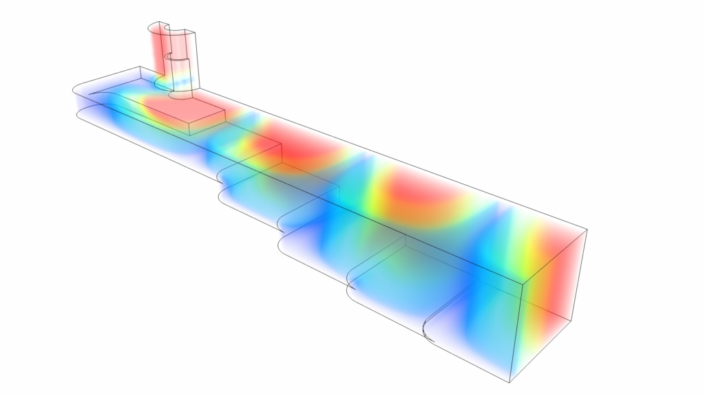
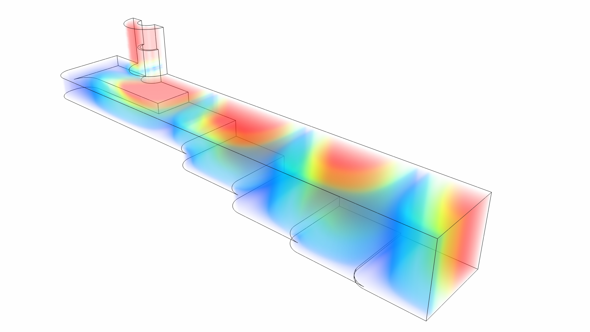
On the capacity front of electromagnetic simulation, HFSS has been an industry leader. Engineers have always wanted to simulate ever larger and more complex designs. From the early days of HFSS with the solution of the coax-to-waveguide adapter shown in the image, designers have clamored for the ability to include larger 3D models, more detailed mechanical and electrical CAD, as well as more complicated material properties. When HFSS was introduced, a then complex coax-to-waveguide adapter took approximately 10,000 matrix elements and 10 hours to solve just a single frequency point. That same model today solves an entire band of frequencies in under 30 seconds on a laptop. The original full-wave FEM solution has grown from solving simple waveguide components to entire microwave systems, complex antenna arrays, and entire printed circuit boards.

There are many algorithmic innovations leading to the unprecedented scale users can solve in HFSS today. We have tackled problems such as multi-processing matrix solutions to distributing these solutions across dozens of compute nodes and hundreds of cores. HFSS introduced the first commercially available Domain Decomposition Method solver for full-wave electromagnetics leading to the ability to mesh and solve pieces of a large problem, then bringing them together for a full model field solution. Whether it is creating, developing, and commercializing new computational electromagnetic algorithms or more efficiently storing information, these enhancements have exponentially increased the speed and capacity of HFSS over the years. One recent example of large-scale IC simulation in HFSS can be seen here.
Some would claim that the increase in capacity is largely due to hardware innovation over the thirty-year history of HFSS. These hardware improvements, described in 1964 by Gordon Moore, and colloquially known as Moore’s law, have magnified these algorithmic developments. Floating point operations have improved in speed by almost 500 times since HFSS was first introduced. Combining the raw clock speed improvements of CPUs with the increased size and speed of cache and main memory, larger simulations can be performed in less time.
It is not much of a stretch to state that engineers have very little patience to wait for simulations. In my experience, the happiest engineer would be one who could solve an entire complex electromagnetic system within seconds from the comfort of their living room on their tablet. For some, the reality of working from home has been realized recently, but we are still not to the point of being able to solve these systems in seconds. However, using the Ansys Cloud and HFSS, these simulations can be accessed and monitored from the comfort of your phone or tablet.
Ansys Distinguished Engineer, Dr. Larry Williams notes that “the numerous electromagnetic method innovations in Ansys HFSS have enabled solutions that now propel the 5G, RF, Wireless, and high-speed industries.” To find out more about the innovations in the HFSS solvers and the history of our HPC computing advancements, take a look at these videos:
https://www.youtube.com/watch?v=N7v4fgDyxB4&list=PLQMtm0_chcLx5STq8Q_p1m79PyjkylvR8&index=3
https://www.youtube.com/watch?v=DC-SA4hloHQ&list=PLQMtm0_chcLx5STq8Q_p1m79PyjkylvR8&index=6
Also Read
HFSS Performance for “Almost Free”
The History and Significance of Power Optimization, According to Jim Hogan
The Gold Standard for Electromagnetic Analysis
Share this post via:


Comments
There are no comments yet.
You must register or log in to view/post comments.