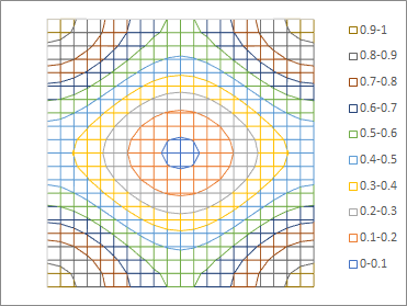
In the assessment of wafer lithography processes, normalized image log-slope (NILS) gives the % change in width for a given % change in dose [1,2]. A nominal NILS value of 2 indicates 10% change in linewidth for 10% change in dose; the % change in linewidth is inversely proportional to the NILS. In a previous article [2], it was shown that NILS is better for a dark feature against a bright background than the other way around. Attenuated phase shift masks (attPSMs) help to improve the NILS to reach values of 2 or more, in cases where conventional binary masks can’t without an exorbitantly high dose.
Increasing the transmission of the attenuated phase shift mask [3] takes the improvement further. A higher transmission effectively makes the dark areas darker, which increases the image log-slope.

Figure 1. NILS is improved for higher transmission of the attenuated phase-shift mask. The images are taken along the long axis of a dense oblong (1.3:1) pattern with cross-dipole illumination. The graph on the right uses the log scale instead of linear scale for the y-axis, representing intensity. The more obvious dip indicates better NILS for the higher transmission (16% vs 6%).
Besides improving NILS, the mask error sensitivity and depth of focus are also improved [3]. Improving the NILS is particularly important for improving the resolution of 2D shapes such as in Figure 1 or in the header above this article. For the 12% attPSM of Ref. 3, a square feature width of 65% of pitch with cross-dipole illumination (for tightest 2D resolution: dipole illumination in X + dipole illumination in Y) just manages to hit a NILS of 2.0 in both x and y. This is another opportunity to improve 2D resolution for DUV, especially for core patterning for self-aligned double patterning (SADP) [4].
References
[1] C. A. Mack, “Using the Normalized Image Log-Slope,” The Lithography Expert, Microlithography World, Winter 2001: http://lithoguru.com/scientist/litho_tutor/TUTOR32%20(Winter%2002).pdf
[2] F. Chen, “Phase-Shifting Masks for NILS Improvement – A Handicap for EUV?”, https://www.linkedin.com/pulse/phase-shifting-masks-nils-improvement-handicap-euv-frederick-chen
[3] T. Faure et al., “Development of a new high transmission phase shift mask technology for 10 nm logic node,” Proc. SPIE 9984, 998402 (2016).
[4] H. Yaegashi et al., “Overview: continuous evolution on double-patterning process,” Proc. SPIE 8325, 83250B (2012).
This article first appeared in LinkedIn Pulse: NILS Enhancement with Higher Transmission Phase-Shift Masks
Also Read:
Assessing EUV Wafer Output: 2019-2022
Application-Specific Lithography: 28 nm Pitch Two-Dimensional Routing
Share this post via:


The Intel Common Platform Foundry Alliance