







Temperature is often treated as a reliability clock.
Increase the temperature, accelerate the failure mechanism, and estimate the equivalent field life.
That approach can be useful—but only when the dominant failure mechanism is known, its thermal activation behavior is understood, and the same mechanism remains active during both the accelerated test and normal operation.
A complete electronic system is rarely that simple.
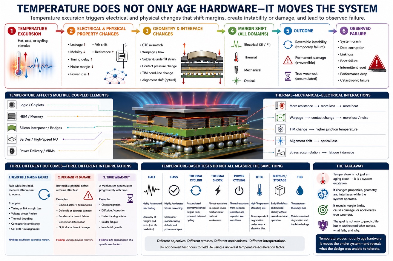
Temperature does not merely accelerate aging. It changes the electrical, mechanical, material, and geometric state of the system while the system is operating.
That creates a more complete chain:
temperature excursion → electrical and physical-property changes → geometry and margin shift → functional instability or damage → observed failure
This distinction matters because not every failure observed at elevated temperature represents the same reliability outcome.
Temperature Changes Electrical Behavior
As temperature changes, semiconductor and interconnect behavior also changes.
Temperature can alter:
- transistor leakage;
- threshold voltage;
- carrier mobility;
- propagation delay;
- clock and data timing;
- conductor resistance;
- power-delivery loss;
- regulator behavior;
- memory and SerDes margin;
- noise sensitivity.
A system that operates correctly at room temperature may begin to fail at elevated temperature—not because it has already consumed its useful life, but because its operating margin has temporarily collapsed.
A timing path may become slower. A voltage rail may experience greater droop. A high-speed link may lose eye margin. A memory interface may become more sensitive to skew or simultaneous switching noise.
The resulting symptoms may appear as software crashes, corrupted data, boot failures, link retraining, memory errors, or intermittent resets.
The software reports the failure. But the cause may be a temperature-induced change in the physical operating margin.
Temperature can also create reinforcing feedback.
As conductor resistance rises, power-delivery loss may increase. The additional loss generates more heat, while changes in TIM condition, cooling performance, or package geometry may make that heat more difficult to remove. What begins as a modest temperature rise can therefore reduce electrical margin and thermal margin at the same time.
The resulting failure is not necessarily caused by one component crossing one fixed temperature threshold. It may emerge from a coupled shift across the complete system.
Temperature Changes Geometry
Temperature also moves the package mechanically.
The die, interposer, substrate, solder, underfill, thermal interface material, lid, PCB, connector, and cooling structure do not expand identically.
As temperature changes, the system may experience:
- package bow;
- die or substrate warpage;
- solder-joint deformation;
- contact-pressure variation;
- connector movement;
- TIM bond-line change;
- optical-alignment shift;
- changes in local mechanical stress.
These geometric changes can modify electrical and thermal behavior.
A connector that is marginally engaged may become intermittent. A warped substrate may alter solder loading. A changing TIM bond line may increase junction temperature. An optical interface may lose coupling efficiency. A package resonance, return-current path, or contact condition may shift.
Temperature is therefore not only a scalar value measured at the junction or case.
It is a physical excitation applied to a coupled structure.
Three Different Outcomes Must Be Separated
When a system fails during thermal testing, the observed result should not automatically be labeled as accelerated aging.
At least three different outcomes are possible.
(1) Reversible Margin Failure
The system fails while hot or cold but recovers after returning to normal temperature.
Examples may include:
- timing-margin loss;
- temporary link failure;
- voltage-margin collapse;
- thermal throttling;
- connector intermittency;
- optical misalignment;
- temperature-sensitive calibration drift.
The system may not yet have suffered permanent physical damage.
The test has exposed insufficient operating margin.
That is still an important reliability finding. A product that fails within its intended environmental range is not acceptable merely because it recovers afterward. But the correct conclusion is that the operating margin was inadequate—not necessarily that a wear-out mechanism consumed a predictable amount of product life.
(2) Permanent Damage
The temperature excursion or associated mechanical stress creates an irreversible defect.
Examples may include:
- cracked solder;
- delamination;
- damaged dielectric;
- permanent connector deformation;
- bond failure;
- package cracking;
- damaged optical attachment;
- material degradation beyond recovery.
The failure remains after the system returns to normal temperature.
This is damage—but it is not automatically equivalent to normal field wear-out.
The test may have exceeded an operational or structural limit. It may have activated a failure mode that would be unlikely under the intended field profile, or it may have revealed a genuine design weakness that normal use would eventually expose.
The distinction requires physical evidence.
(3) True Wear-Out
A specific failure mechanism accumulates progressively with time, temperature, cycling, electrical stress, or another applied load.
Examples may include:
- electromigration;
- diffusion;
- corrosion;
- dielectric degradation;
- solder fatigue;
- interfacial growth;
- polymer aging;
- repeated thermomechanical fatigue.
This is where mechanism-specific acceleration models become valuable.
An Arrhenius-type relationship may be appropriate for a thermally activated chemical, diffusion, or degradation mechanism when the activation energy is known and the mechanism remains unchanged across the test and field temperature ranges.
Cycling-related failures may require models based on strain range, temperature range, dwell time, ramp rate, and cycle count. Depending on the mechanism, approaches such as Coffin–Manson or Norris–Landzberg may be more relevant than a simple temperature-time conversion.
No single model applies universally.
The physical failure mechanism must first be identified. Without that evidence, temperature alone should not be treated as a universal clock that converts test hours directly into product life.
Thermal Testing Should Discover the Limiting Structure
The strongest use of temperature is not only to accelerate a predefined mechanism.
It is also to expose where the complete system loses margin.
A good thermal investigation should ask:
- Did the failure occur only at temperature?
- Did the product recover?
- Was permanent damage created?
- Did the failure accumulate gradually or appear suddenly?
- Was the dominant change electrical, mechanical, thermal, optical, or material?
- Did the same mechanism exist under expected field conditions?
- Did manufacturing variation make some units fail earlier than others?
- Was the observed symptom the actual failure mechanism or only its system-level consequence?
This changes thermal testing from a simple time-compression exercise into a discovery process.
The correct test should therefore be selected according to the engineering question.
Is the objective to discover a margin limit? Reproduce structural damage? Accumulate fatigue? Screen manufacturing defects? Or predict a known wear-out mechanism?
Those objectives are different, and they require different stresses, measurements, failure criteria, and interpretations.
The Package Makes the Problem More Coupled
In heterogeneous integration, temperature affects many boundaries simultaneously.
A modern package may combine:
- logic;
- HBM;
- chiplets;
- silicon bridges or interposers;
- high-speed SerDes;
- power delivery;
- optical engines;
- underfill;
- TIM;
- lids and heat spreaders;
- liquid- or air-cooling structures.
A temperature excursion can change semiconductor timing, PDN resistance, package warpage, solder stress, TIM condition, optical coupling, and cooling performance at the same time.
The observed failure may emerge from the interaction of several small margin shifts rather than from one isolated component exceeding a simple temperature limit.
For example, higher resistance may increase local power loss while package deformation changes contact pressure and TIM bond-line thickness. Junction temperature then rises further, timing margin decreases, and a high-speed interface begins to retrain or fail.
The system may report a digital error even though the underlying cause is an electrical-thermal-mechanical interaction.
This is why complete-system reliability cannot be reduced to one acceleration factor.
A Better Reliability Chain
The more useful framework is:
temperature profile
→ property changes
→ geometry and interface changes
→ electrical, thermal, mechanical, and optical margin shifts
→ temporary instability, permanent damage, or accumulated wear-out
→ observable system failure
The final step is critical.
The system may report a memory error, software crash, link loss, or boot failure.
But those are symptoms.
Reliability engineering must work backward from the observed failure to the physical mechanism.
That requires correlating system logs and functional data with physical measurements such as temperature, voltage, current, timing, strain, warpage, optical power, contact resistance, and post-test failure analysis.
Without that correlation, the reported system failure may be mistaken for the mechanism that produced it.
Temperature-Based Tests Do Not All Measure the Same Thing
Temperature appears in many reliability and qualification methods, but those methods should not be interpreted as equivalent.
HALT—Highly Accelerated Life Testing—uses progressively severe temperature, rapid thermal transitions, vibration, and sometimes combined stresses to expose weak design margins and identify operational or destructive limits. Its primary purpose is discovery, not direct field-life prediction.
HASS—Highly Accelerated Stress Screening—uses controlled stresses derived from HALT learning to identify manufacturing defects or process escapes in production. It is a screening method and must be designed carefully so that it reveals defects without consuming unacceptable product life.
Thermal cycling repeatedly moves the product between hot and cold conditions. It is especially valuable for studying accumulated thermomechanical fatigue caused by CTE mismatch, solder deformation, warpage, delamination, and interface loading.
Thermal shock applies more abrupt temperature transitions and can expose severe mechanical or material weaknesses that may not appear under slower cycling. The transition rate itself becomes part of the applied stress.
Power cycling creates temperature excursions through internal electrical dissipation. It is particularly important when local junction heating, interconnect fatigue, die attach, or package interfaces experience repeated operating loads. The resulting temperature gradients may differ significantly from those produced by chamber-based thermal cycling.
HTOL—High-Temperature Operating Life—combines elevated temperature with electrical bias to investigate time-dependent semiconductor degradation and specific wear-out mechanisms.
Other methods—including burn-in, high-temperature storage, and temperature-humidity-bias testing—address early-life defects, material stability, corrosion, leakage, and insulation degradation under different combinations of environmental and electrical stress.
These tests do not ask the same question:
- HALT discovers where system margin collapses.
- Thermal and power cycling investigate accumulated thermomechanical fatigue.
- HTOL and related tests evaluate time-dependent degradation mechanisms.
- HASS and burn-in screen for manufacturing or early-life defects.
- High-temperature storage evaluates material and interface stability without normal electrical operation.
- Temperature-humidity-bias testing examines moisture-assisted electrical and material degradation.
Therefore, a failure observed during one test should not automatically be converted into field life using a universal temperature-acceleration factor.
The test method, applied stress, observed symptom, physical failure mechanism, and expected field condition must all be connected before a lifetime conclusion is justified.
The Takeaway
Temperature remains one of the most powerful stresses available to reliability engineers.
But it should not automatically be treated as a universal clock.
Temperature can reveal insufficient margin, create permanent damage, or accelerate a genuine wear-out mechanism. These are three different reliability outcomes, and they require three different interpretations.
The purpose of thermal testing is not merely to calculate how quickly life has been consumed.
It is to discover how the system changes, where its margins disappear, what physical mechanism is responsible, and whether the observed failure truly represents field aging.
Temperature does not only age the hardware.
It moves the entire system—and reveals what the design was unable to tolerate.
Also Read:
The Difference Between TSMC CoWoS-S and CoWoS-R
From Process Learning to Production Control: Characterization for the Era of Heterogeneous Systems
Share this post via:



The silent killer of analog reliability: Why SPICE misses floating net