webinar banner AI 2026 v2

Bug Trace Minimization. Innovation in Verification

Bug Trace Minimization. Innovation in Verification
by Bernard Murphy on 09-22-2020 at 6:00 am

innovation min

A checker tripped in verification. Is there a bug trace minimization technique to simplify manual debug? Paul Cunningham (GM, Verification at Cadence), Jim Hogan and I continue our series to highlight all the great research that’s out there in verification. Feel free to comment.

The Innovation

This month’s pick is Simulation-Based Bug Trace Minimization With BMC-Based Refinement. We found this paper in IEEE Transactions on CAD, 2005. The authors are/were from the University of Michigan. This is an old paper but still intriguing.

Debug, tracing back from an identified bug to the root cause, is  the biggest time-sink in verification. Any contribution to reducing that time will have high value. The authors’ approach starts with a waveform trace from a simulation or semi-formal analysis. It aims to reduce the trace to a much shorter trace that still triggers the bug, an easier starting point for manual debug.

The paper describes four simulation-based and one BMC-based technique to reduce traces. They first reduce traces by removing cycles, re-simulating each time to check the bug still reproduces. At first glance this looks very unscalable, requiring O(N2) runs for a trace of N cycles. They greatly reduce this complexity first by hashing the circuit state at each cycle. They then watch for hash matches between the original trace and a re-simulation of a candidate reduced trace. If a previously hashed state is hit during re-simulation, they know that the bug can be reached from that hashed state. They can abort the simulation since it can still trigger the bug, i.e. the reduction is proven viable.

Through this process they look for any variant trace which triggers the check sooner, which becomes a new and shorter reference trace. Alternatively it may hit a state already seen in an earlier analysis at a later clock cycle. Then this trace can skip ahead, also leading to a shorter reference trace. In a final high-effort simulation step, they also look for opportunities to drop input events (rather than whole cycles), as shown in table 3.

Using common datapath functions, FPU, DES and a picoJava engine as benchmarks, the authors show impressive reductions in cycle lengths, better than 98% in most cases and better than 99% in all cases in removing unnecessary inputs. Runtime on most tests was under a minute. The most complex (picoJava) was 10hrs for 30k cycles. Reduced traces were mostly under 10 cycles.

Paul’s view

This reminds me of an earlier paper we discussed “Using AI to locate a fault”. Both combine multiple methods in fault tracing, getting more out of the combination than out of any one method alone. This approach combines five methods, four simulation-based and one BMC-based. The results, e.g. in figure 12, clearly show how different techniques have different impact on different testcases. Which underlines that you really need all these methods. For a commercial vendor this looks very practical, a fusion of methods rather than a single super-method. Tables 5 and 6 show the bulk of reduction coming from simulation methods and a smaller incremental benefit from BMC. Also encouraging for commercial mass deployments given scalability considerations for model-checking.

Intuitively the method makes a lot of sense. State hashing and looking for matches will almost certainly be very effective on randomized simulations. It’s the classic computer science random walk problem where the drunken man walking randomly is going to do a lot of circling relative to the amount of actual useful distance moved. All these circles quickly prune away by looking for state hash matches, which should massively reduce practical runtimes.

In their experiments picoJava (around 140k gates) ran in 10 hours. That was running a 1GHz Sun blade (2005 remember). Now 3GHz servers are typical, so you’re looking at 500K gates in 10 hours for a single CPU job on a modern server farm. The algorithm is also very parallelizable, so can be scaled up by just farming re-simulation jobs out to multiple servers, sharing the same state hash database. Which makes it very commercially interesting.

Jim’s view

Moving this into the cloud seems a great way to speed up and reach for larger designs. Thinking about it, 10 hours is an overnight run. You could slipstream these runs in behind regression runs. By the time the verification team had a chance to look at them, most or all of those traces would already be reduced.

On investment, this naturally fits into the verification suite, so it’s not an independent product. A bit of a challenge is that this is speeding up something engineers already do rather than making something possible that wasn’t possible before. Can it in some way show a huge improvement in productivity? Maybe add an AI angle for 100X improvement over time? That could enhance appeal for an investor.

My view

First, while a lot of good ideas come from software verification, it’s nice to see some coming from hardware verification. Second, I had been looking mostly for recent papers. Paul pushed me to look at some older papers as well. Good intuition!

Click HERE to see the previous Innovation blog

Also Read

Anirudh CadenceLIVE Plays Up Computational Software

Lip-Bu Hyperscaler Cast Kicks off CadenceLIVE

Quick Error Detection. Innovation in Verification


WEBINAR: UVM RISC-V and DV

WEBINAR: UVM RISC-V and DV
by Daniel Payne on 09-21-2020 at 10:00 am

UVM Testbench RISC-V

Oh, our semiconductor industry just loves acronyms, and the title of my blog packs three of the most popular acronyms together at once. I attended a webinar hosted by Aldec last week on this topic, “UVM Simulation-based environment for Ibex RISC-V CPU core with Google RISC-V DV“. Verification engineers have been adopting the Universal Verification Methodology in order to make their verification results more robust, in less time.

RISC-V continues to grow in importance as an open source, Instruction Set Architecture (ISA), and at the dac.com site there are some 3,110 search results for RISC-V. I just expect this trend to continue, because engineers often want to customize aspects of their SoC for a specific purpose or domain. A big question then arises on how do you actually verify a RISC-V project.

Google has created a SV/UVM based instruction generator for RISC-V processor verification, then posted it on GitHub. There have been some 765 commits, so this is an actively supported instruction generator.

There are many RISC-V core projects around the world to choose from, and Ibex is a small, 32-bit RISC-V core, also available on Github with 1,860 commits to date.

Using Riviera-PRO Aldec simulates the UVM testbench with the Google DV random instruction generator and Ibex RISC-V core.

Source: https://ibex-core.readthedocs.io/en/latest/verification.html

In the testbench SV classes are blocks with rounded corners, while SV modules are shown as square corners, finally the code to be run is depicted in blue with folded corners.

Random commands come from the Google DV generator, and the testbench also has random interrupts during testing. The co-simulation flow has both an ISS and RTL loaded with test binaries, simulations are run, then the results are compared by a Python script. You can have the same verification experience if you assemble all of the pieces:

  • SystemVerilog simulator that supports UVM (i.e. Riviera-PRO)
  • Instruction Set Simulator (Spike or OVPsim)
  • RISC-V toolchain

Here’s the flow of tools and files used for verification:

The second half of the webinar was showing an actual, live demo of this verification flow in action, running the makefiles, scripts, simulators and comparison on a Linux platform. Batch mode verification was shown first verifying the Ibex core, then GUI mode was run next, and in both cases there were zero mismatches between the ISS and Riviera-PRO simulator results.

The GUI for Riviera-PRO had multiple windows: Source code, Classes, Assertions, Messages. In the upper right is the Classes Window, showing instances and hierarchy, methods, properties, derived classes and base classes.

A very useful documentation feature was how a UVM graph could be auto-generated within Riviera-PRO, as it showed memory interface agents, one interrupt agent, connections, and then stepped into instances for more details to understand connectivity.

An assertions window showed all assertions in one place, without having to look at multiple files, while seeing any failures, passes, and the time when it last happened, quite useful for debugging.

Next, the waveform viewer was invoked after restarting simulation, and they added waveforms from the DUT.

Finally, they showed the RTL code coverage after simulation had finished, then generated an HTML cumulative summary.

Summary

RISC-V is one of the biggest topics of 2020 for the electronics industry, and the ecosystem continues to grow each day, but verification can be a burden. Aldec showed in this webinar how their SystemVerilog simulator along with other tools could be used in verifying a RISC-V core called Ibex.

I’ve included links to each open source tool on Github, so go explore on your own and save some verification time, instead of starting from scratch.

To watch the archived webinar, visit here.

Related Blogs


CEO Interview: Murilo Pilon Pessatti of Chipus Microelectronics

CEO Interview: Murilo Pilon Pessatti of Chipus Microelectronics
by Daniel Nenni on 09-21-2020 at 6:00 am

MuriloPessatti Photo

Murilo Pilon Pessatti is an Electrical Engineer with a MSEE in Analog IC design. He studied in Brazil at São Paulo University (USP) and earned a masters at Campinas State University (UNICAMP). Murilo then moved to Lisbon in Europe to work for ChipIdea, in the early 2000’s when the smartphone era was just taking off.

“I had the distinct pleasure to work in one of the first first Analog IP companies, where I had the chance to learn a lot and very fast about Power Management for portable devices. I came back to Brazil and after spending 2 years in a public semiconductor company and decided to start Chipus.”

Please tell me about Chipus
Chipus is a mixed-signal IC design company. We have strong analog expertise, mixed up with significant know-how in digital state-of-the-art technologies. We help our customers to develop the next generation of key IoT, Industrial, Sensors, AI and RF/Optical Communication ASICs. In these almost 12 years since we started the company we had the opportunity to develop almost 400 IPs in mixed-signal areas, tapeout lots of projects, develop very interesting full turn-key ASICs and have a lot of fun working with very challenging and smart customers — something that really motivates us!

What problems does Chipus solve? 
Chipus was born with the power-aware mindset. Since the beginning in 2009 when we started building our IP portfolio, we pushed the limits to deliver the lowest power IPs and ASICs. So definitely, when the whole IoT and AI wave hit the market, we were very well positioned to solve all the power related problems based on the IPs and experience we accumulated in the last decade. The key approach and differentiation we have is based on our solid expertise and know-how in operating transistors in weak and moderate inversion. We have both practical ( many tape-outs our team have done dealing with very low power circuits) and solid theoretical experience and background in this field (we are lucky to have a group of researchers in the university very close to us that has developed one of the most accurate charge-based physical models operating in all-region). Adding all of this on top of the portfolio of IPs we have created in the last decade put Chipus in the lead position to solve key power-related problems in IoT and AI to the edge systems and ASICs.

We started back in early 2009 building our IP portfolio and as we start gaining credibility from the market by licensing our IPs, our customers start to ask us to help them integrate ours and 3rd Party IPs in their SoCs. We end up not only helping them but also start providing a kind of differentiated design services for customers that really need a high quality team working very close and collaboratively with their SoC architects. At the same time, we start expanding our IP offering, to the point that nowadays we also have high-speed and high-precision building block IPs. Because all these IPs and SoCs had also significant digital blocks, we also built a very experienced digital team that gained a lot of traction in the recent years providing full RTL-to-GDSII flow in state-of-the-art technologies. Last but not least, it was very natural in the last years for Chipus to extend our high quality integration IP services to a complete full ASIC offer, that we start to see a big momentum in different market segments, not only in IoT, industrial but also RF/optical communication.

How has the market changed for Chipus in the past 10 years?
I see all of the high dynamics in the semiconductor M&A area as a big opportunity to Chipus. But the most important thing for us is to continue doing our high quality work for our customers, even when these customers are merged or acquired by other companies, most of the time we keep working with them, and sometimes our business even grows as they merge with other bigger companies. We are always searching for new challenges and to find out how we can give the best support to our customers, so that all of this market consolidation did not really affect our business and goals as a company.

I do believe that IoT, AI to the edge and optical communication are very promising market segments. It is easy to understand: more and more all these “things” are portable and more functionalities need to be done on the edge to be real time. On the other hand, all those things end up putting lots of bits on the internet, which simply cannot afford to use copper anymore. All of this with just some “pico-joules” of energy to make sure batteries last long. That is for me a big opportunity to solve key problems.

What type of customers does Chipus look for?
We have all types of customers, we never give up to offer the best quality, does not matter the size of the customer, we will be there. We have worked with some small start-ups that end up having very significant exits and become part of big companies. Sometimes we have customers that we license some IPs, sometimes we have customers that need help in a key project in which we come in and increase their capability to solve problems, and sometimes we have customers that want us to develop a full turn-key ASIC. The common point is that in almost all the cases, those customers come back and ask us again for our support. We have some long term customers for who we work constantly and for a long term period. We always see our customers and the business as a relationship and not as a transaction. We expect for a typical customer the same.

Time-to-market, first-time-right and price are for sure a big concern from customers. Especially when we have the first interactions with the customers these requirements are more prominent. As far we start the engagement and the trust is developed, things tend to go more smoothly and the most important thing is to be lined up with the long term objectives and goals of the customers. We usually work in very close relationships with our customers long term goals.

About Chipus
Chipus Microelectronics (ISO 9001:2015 certified) is a semiconductor company focused on the development of mixed-signal ASICs, intellectual property (IP) blocks and IC design services. The company has more than 200 analog IP blocks in process nodes from 22nm to 0.35um of various foundries. Since its foundation in 2008, Chipus has worked with customers worldwide (South and North America, Europe, and Asia) with firm commitment and flexible client support.

Besides analog and mixed-signal expertise, Chipus also offers custom digital IC design services having successfully delivered designs in 7nm from RTL to backend. Headquartered in Florianópolis, Brazil, Chipus has a US subsidiary in Silicon Valley and sales teams in both USA and Europe.

For additional information on Chipus or its services, please contact us here.

Also Read:

CEO Interview: Pengwei Qian of SkillCAD

CEO Interview: Charlie Janac of Arteris IP

CEO Interview: Anna Fontanelli of Monozukuri


From Moore’s Law to Moortec’s Law!

From Moore’s Law to Moortec’s Law!
by Tim Penhale-Jones on 09-20-2020 at 10:00 am

Moortecs Law

No-one likes being put on the spot and yet we all like a forecast…and as we all know, the only guarantee with a forecast is that it is wrong. Sports commentators have carved out a special niche for themselves with the ‘commentators curse’, just as they extol the virtues of an individual or a team, the sporting gods prove them wrong in spectacular fashion! Governments are no better…economic forecasts don’t usually hold for more than a quarter, which is what makes Gordon Moore’s prediction all the more impressive.

I’m sure everyone in our industry is familiar with Moore’s Law… while at Fairchild Semiconductor in 1965 he was asked to contribute to the 35th anniversary Electronics Magazine with a prediction for the future of the semiconductor components industry over the next 10 years…his response was ‘the number of transistors in a ‘dense IC’ would double every two years’! What a prediction, it was correct for the next 50 years and is only now starting to ‘fade’, surely the SWAG* to beat all SWAGs?!

So what has Moore’s Law got to do with Moortec?

Broadly speaking he predicted that over time transistor density would increase, so more could be put on anyone device…and predictably devices would grow. This wasn’t really an issue in the early days, when geometries were measured in micrometres, in fact all the way down to 40nm there weren’t any major issues, it was the transition from planar to FinFET technology where things started to change. The bit Gordon wasn’t too explicit on was the change in leakage current as we ride the geometry wave, leakage current starts to become an issue in FinFET and is just plain ugly sub 7nm, add to which the chip sizes grow significantly as the applications of the day try to maximise the benefits of these plentiful transistors.

Ok, big deal…chips get bigger, leakage increases, power density is now also increasing with the ‘end’ of Dennard Scaling, you don’t need to be Nostradamous to predict that things will start to warm up a little. Yet that isn’t the only effect you’ll be seeing, temperature is a first order effect…as the heat rises so data throughput drops, power consumption increases and so the cycle builds on itself.  Second order effects then come into play, the silicon starts to age, reliability takes a hit and can have knock-on effects into your system reliability and overall performance.

Great man though he was, Gordon didn’t mention any of that.

So here is where Moortec’s Law comes in (just for the record, I’m not claiming it will last 50 years!)…‘the number of sensors used in a ‘dense IC’ will (at least) double per geometry shrink’. There is a second Law (as with Gordon, he too had a second, less well known Law), ‘the number of sensors used in individual designs will rise exponentially as engineers appreciate the information they can divulge in mission mode’!

The proliferation of sensors in SoCs will not only be driven by better understanding of the value of the data they provide, but also a deeper appreciation of the type of data they can provide in different areas of a design. Imagine baking a souffle in an oven without a glass door, you are blind to what is happening inside. You’ve followed a recipe and yet you can’t be sure the eggs were a uniform size or the flour was a consistent strength or that the oven holds it’s temperature evenly throughout the cooking process…until you open the oven door, you don’t know what to expect…open it too soon and it will sink, too late and it will have burnt!

SoCs are no different, except the cost of failure is many orders of magnitude greater, that ‘mission mode’ visibility the glass door provides is no different from having 10s, 100s or even 1000s of sensors in your device.

*Scientific Wild-Ass Guess

In case you missed any of Moortec’s previous “Talking Sense” blogs, you can catch up HERE.

WEBINAR: Addressing the Challenges of Hyper-scaling within Data Centers with Advanced Node Embedded Sensing Fabrics


Protocol in Depth – Ethernet

Protocol in Depth – Ethernet
by Luigi Filho on 09-20-2020 at 6:00 am

Protocol in Depth Ethernet

Many times i notice people “kind of afraid” of some protocol, trying to avoid the usage because “it’s complicated”, I decide to go in-depth in one and show that maybe it’s not so complicated after all. First challenge is choosing the protocol and decide about the Ethernet, because this protocol has many challenges in my mind, and it’s well-known, old, has many standards, have misconceptions that another protocol, like USB or HDMI don’t.

WARNING

I’ll try to show the protocol in low-level (bit level) in few words possible, many things will be missing in this text, so don’t use this text to do any ethernet work related.

The Ethernet was started in 1973, but only in 1990 was released the standards IEEE 802.3i that is known as Ethernet 10BASE-T or “10Mbit Ethernet”, and the first point is that there were some standards before, like the DIX Ethernet, StarLAN and LattisNET. I don’t think theses protocols are used today, so I’ll ignore them and focus only on the IEEE 802.3i, that I’ll call “Ethernet”.

Other point is the IEEE 802.3 standard, is a collection of standard so, we have Ethernet over Coax cable, twisted pair, Fiber-Optic, and many other options. Again the focus is the 10BASE-T (10 is refer of 10Mbit, the BASE refer signaling BASE or BROAD and T refer twisted pair).

The ethernet standard 802.3i will cover only the physical and data link of the OSI model, but in the data link layer will be divided into MAC (media access control) and LLC (logical link control), the 802.3i only cover the MAC layer, don’t cover the LLC layer, this is cover in 802.2.

For a designer that want to include the ethernet in your project (Considering a IC Designer) you will need design theses.

Physical layer (Mostly Analog IC Designer)

All communication is transmitted by a differential driver and will have the deal with some encoded data in and out as the control in and out.

All data will be encoded in Manchester encode and will communicate in full-duplex or half-duplex.

Media Access Control Layer (Digital IC Designer)

Uses CSMA/CD control access and will receive and send a frame that will be describe below:

1 – Preamble

2 – SFD

3 – Destination Address

4 – Source Address

5 – Length/Type

6 – MAC Client data / PAD (Payload)

7 – Frame Check Sequence

8 – Extension (optional)

1 – Preamble is a 7 bytes(56 bit) that is sent to allow the PHY layer reaches a steady state, these bytes is:

10101010 10101010 10101010 10101010 10101010 10101010 10101010

2 – SFD is the Start Frame Delimiter show the start of the frame, this is one byte (8 bit):

10101011

3 and 4 – Destination and Source Address, both is an 6 bytes (48 bit), that theoretically represent a unique identifier for each equipment.

5 – This can represent two types of data, in 2 bytes (16 bits) the length or type of the following data.

6 – This is the data to be sent, or message, can be 46 to 1500 bytes long (368 to 12000 bits) and at the end is included a PAD. Any other protocol will be in it.

7 – This is a CRC calculation of the Destination and source address, length/type field and data/pad field, and is attached in the end of data/pad field, that has 4 bytes (32 bits) long.

8 – It’s not transmitted in half-duplex mode, is transmitted until complete the time frame.

There are many controls and processes that the MAC Layer will execute, but i don’t think this will very interesting to show in this post. And there is no way that i can show every detail of the standard in some small internet post.

But as you can see, isn’t complicated to implement, sometimes it’s hard to get some information if it’s old, or maybe pay for the standard and understand it.

It’s totally possible to a designer implement any standard, the most complicated is understand the standard that is written not in a very practical way, this need practice to understand it.


WEBINAR: Design Adaptive eFPGA IP

WEBINAR: Design Adaptive eFPGA IP
by Daniel Nenni on 09-18-2020 at 10:00 am

Menta Adaptive Design eFPGA Webinar 1

Since the start of PROMS, PLDs and FPGAs we have learned the importance of programmability in modern semiconductor design. Today we have eFPGAs for “design adaptive” embedded programmability and that is what this webinar is all about.

Several key points are discussed starting with the Law of Accelerating Returns as it applies to integrated circuits followed by Semiconductor Trends, the Makimoto Wave, and Design Cycles & Rhythms of Change. This is a great overview for the young and old, absolutely.

We then dig into the nuts and bolts of FPGA, ASIC, SoC, Processors and  eFPGAs followed by the Menta Design Adaptive eFPGA IP and the benefits of programmable logic without the pain.

The speaker is Yoan Dupret, whom I met at the Design Automation Conference a few years back. Yohan is an innovator with a PhD and more than 15 years experience in the semiconductor industry including various management and technical positions in companies such as DelfMEMS, Samsung, CSR, Infineon and Altis Semiconductor prior to Menta.

In addition to his embedded FPGA expertise, Yoan worked on topics such as RF MEMS design, EDA, PDK, MOS and passives RF modeling, statistical simulation and manufacturing yield modeling.

As I have mentioned before, it is a privilege to work with so many incredibly intelligent people inside the semiconductor ecosystem and Yoan is one of those people, absolutely.

Register HERE for the replay.

Abstract:
Despite the current health crisis, we are living through an unprecedent era of innovation – and this is not going to slow down as well captured by the law of accelerating returns. Disruptive and rapid change is now the new constant. The rate of architectural and algorithmic innovation is outpacing traditional chip development cycles. This is not only true for AI, but also for communication protocols, encryption, compression, interconnect fabrics and cybersecurity. The old world order of computing has now fractured beyond recognition. Now is the time to design chips to be at least partially reconfigurable to adapt to emerging needs.

Embedded programmable logic, in the form of embedded FPGA (eFPGA) IP, is now making its way in SoCs as an answer to these challenges, with multiple design wins announced by the main eFPGA IP providers.

In this webinar, we will explain what makes an eFPGA different to a FPGA but also to embedded CPUs/GPUs – and in which cases an eFPGA IP is the way to go. We will then explain what is a design adaptive eFPGA IP and why this adaptiveness is so important when it comes to integrating an eFPGA IP.

Here are the questions I have for the Q&A. Send me your questions and I will make sure they are answered:

  • If I have RTL working on an off the shelf FPGA, how hard is it to port it to a Menta eFPGA IP?
  • You mention foundries, do you work with IDMs as well?
  • What kind of applications are run by your customers?
  • Is there a way to secure the bitstream?
  • Any export limitations?
  • What percentage of the chip is usually taken by the eFPGA?

Register HERE for the replay.

About Menta
Menta is a privately held company founded in 2007 in France. The company delivers 100% third party standard-cells embedded FPGA IPs for SoC, ASIC or ASSP designs. Our technology lets you effortlessly update your silicon post-production, whether to fix a bug, implement customer-specific features, adapt to evolving standards, or enhance security.  Menta IPs are delivered with the Origami toolchain to generate the bitstream from RTL, including synthesis. Menta is backed by FJ Development EN, with an investment of more than $7M to date.


The History and Physics of Cliosoft’s Academic Program!

The History and Physics of Cliosoft’s Academic Program!
by Srinath Anantharaman on 09-18-2020 at 6:00 am

academic map

It was a very late evening, perhaps 11 PM, on a warm summer night in 2008. Someone sent an email to info@cliosoft.com with a very odd question – why were we not listed in Wikipedia? The sender was a scientist working for the Lawrence Berkeley National Lab. Of course, this piqued my curiosity and I replied back asking why that concerns him so much? After a few email exchanges, I found out that his team was collaborating with scientists in several other research organizations in Europe to design the Atlas detector for the Large Hadron Collider in Switzerland.  They were using the Cadence Virtuoso platform for analog mixed-signal design and looking for a design management solution to help collaborate and share design data efficiently. Of course, being a research organization, they had limited budgets. This seemed like an absolutely worthy project to be associated with and the Cliosoft Academic program was born! Here is a paper in EDN magazine with more information about this project.

We were a small company and we really did not have the resources to promote and nurture an Academic program. However, purely through word of mouth, we got requests for academic licenses from Nikhef in the Netherlands and DESY and the RWTH Aachen University in Germany in 2009. In 2011, two of Europe’s premier research organizations, CERN in Switzerland and CNRS in France adopted the Cliosoft SOS platform. Academic requests started trickling in at a much faster rate, mostly from Europe, even though our Academic program wasn’t even mentioned on our website. Many of them were physics researchers collaborating with one or more of the research organizations using Cliosoft SOS.

Dr. John McLean, Head, Microelectronics Support Centre and Manager Europractice Design Tool Service, came to our DAC booth in 2016. We were surprised by this as our previous attempts to get listed with Europractice had, to be honest, fallen on deaf ears. Europractice supports only a select few EDA vendors and they did not have much interest in a design management vendor.  John was blunt and honest with us. I am paraphrasing, but he said something along the lines of “We didn’t think that there was a big enough interest, but it appears that the Physics community in Europe has standardized on your solution”. The power of physics is how Cliosoft made it to the select list of EDA vendors supported by Europractice.

It took a little while for word to cross the pond but now we have research organizations and universities in North America using our design management solutions. These include research organizations such as Brookhaven Labs, Stanford SLAC, and Triumf, and universities such as Cornell, SMU, Pennsylvania, and UC Santa Cruz.

Since that summer night in 2008, this program has been a special child for me. I feel proud and honored that some of the best minds in the world actually use our software to explore the nature of the universe. While pottering around in COVID-19 isolation, I realized that we now have over 40 academic institutions using our software to help with their deep scientific research. I thought I would write this blog to celebrate that milestone. I reached out to several of the scientists to find out what type of work they are doing and how Cliosoft’s SOS has helped them. Listed below are quotes from some of the smartest people we have had the honor of working with.

If you are engaged in academic or research activities and would like to license our software through our academic program then contact us by emailing: edu@cliosoft.com

Wojciech Bialas

  • Engineer/CAD Manager, Experimental Physics Department
  • CERN – European Organization for Nuclear Research

Microelectronics section at CERN is principally involved in the design of a variety of ASICs related to four major LHC experiments of general purpose: ATLAS, CMS and specialized ones: ALICE, LHCb.

Starting to use Cliosoft suite of tools by our community was clearly a turning point for us. It came really at the right moment. We were in the middle of electronics design challenge for LHC experiments planned upgrades, where the complexity of ASICs foreseen went up by an order of magnitude from what we were doing before. Microelectronics engineers in the High Energy Physics (HEP) community were geographically and institutionally very much dispersed. Collaboration on these demanding projects in that conditions was really difficult. The Cliosoft SOS solution met perfectly our needs, introducing smooth data exchange between HEP community designers. It also brought us design exploration solutions. Inside our CERN microelectronics section we de facto made Cliosoft data management a standard. Considering all these benefits, nowadays all our projects are receiving SOS data management configuration by default. By using it we simply started to be more efficient in our work.

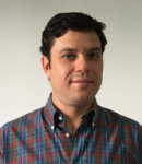
Maurice Garcia-Sciveres

  • Senior scientist, Physics Division, Lawrence Berkeley National Laboratory

ASICs are an integral part of particle physics experiments and many PhD students are involved in IC design projects. However, particle physics experiments are also carried out by large collaborations of people from many institutions all over the world. The ATLAS.ch experiment, for example, has over 1000 PhD students from 180 institutions. People working on a particular ASIC design will generally not be co-located. Collaboration tools are essential to enable students to work on real ICs that will be used in the experiment. Over the past decade, Cliosoft’s SOS has become the standard tool for integrating particle physics ASICS, greatly enhancing student involvement.

Here are just a few of the projects I was involved in:

Luca Pacher, University of Torino, PhD 2015: “Development of Integrated Pixel Front-End Electronics in 65 nm CMOS Technology for Extreme Rate and Radiation at HL-LHC”, developed digital control and readout for high rate pixel detectors. Project was organized with Cliosoft leading to final submission in 2017.

Ennio Monteil, University of Torino, PhD 2017:  “Front-end electronics in 65nm CMOS technology for the HL-LHC upgrade”, has been working on the design of an analog front-end in 65nm CMOS technology inside the CERN RD53 collaboration. This activity relied on Cliosoft for chip integration.

Sara Marconi, Perugia University, PhD 2018: “Design and optimization of low power hybrid pixel array logic for the extreme hit and trigger rates of the Large Hadron Collider upgrade”, designed digital elements and developed UVM verification framework for pixel readout circuit. Full design managed on Cliosoft.

Tomasz Hemperek, Bonn U. PhD 2018: “Exploration of advanced CMOS technologies for new pixel detector concepts in High Energy Physics”, Development of radiation hard monolithic pixel sensors that can replace hybrid pixel sensors in high energy physics experiments in various technologies (110-180nm). Most using Cliosoft.

Veronica Wallangen, U. of Stockholm PhD 2019: “Performance Improvements for Particle Tracking Detectors in Extreme Rate and Radiation Environments”. Designed a 65nm CMOS DFE circuit for 5Mbps NRZ transmission, which was included in a test chip assembled and submitted by collaborators at Southern Methodist University, via Cliosoft.

Cesar Gonzalez-Renteria, UC Berkeley PhD in progress: Worked on digital verification of 65nm CMOS pixel readout chip. Mostly RTL code, but relying on Cliosoft for chip integration.

Piotr Rymaszewski, Bonn U. PhD in progress:  “Design and characterization of pixel IC electronics and sensors for a new pixel detector generations”, Development of radiation hard IP  in 65nm inside the CERN RD53 collaboration and radiation hard monolithic pixel sensor in 150nm technology for ATLAS like environment (LF-Monpix series). Both using Cliosoft.

Kostas Moustakas, Bonn U. PhD in progress: “Development of Depleted Monolithic Active Pixel Sensors with Small Collection Electrode for LHC”, Development of radiation hard IP in 65nm inside the CERN RD53 collaboration and radiation hard monolithic pixel sensor in 180nm technology for ATLAS like environment (TJ-Monopix series). Both using Cliosoft.

Nick Van Helleputte

  • R&D Manager, Biomedical circuits and system, imec

Our team focuses on analog-mixed-signal ASIC design for ultra-low-power biomedical applications. As our team has grown, so did the complexity of our ASIC designs. While initially our research focused on analog readout circuits for various biomedical parameters, we gradually moved towards highly integrated true SoCs with analog readouts, analog-to-digital converters, digital signal processing, power management and wireless communication capabilities all in single-chip solutions. This eventually meant larger design teams and multiple collaborators, sometimes spread across different countries. It became clear that to ensure successful and efficient design, we needed a suitable design management tool.

We opted for Cliosoft SoS and never regretted this decision. Version control is an integral part of a decent quality assurance design flow and is extremely well implemented in SOS. In addition, it allows efficient collaboration across multiple teams. Roll-back to previous versions and design IP re-use are features we have come to rely upon on a daily basis.

However, Cliosoft SOS did not only prove to be valuable for these large ambitious projects. After seeing the benefits SOS offered in our larger research projects, while still being easy to set up and intuitive to use, we decided to make it part of our standard design flow for all design projects. Roughly half of our ASIC designs are PhD researchers who are often working on a research topic by themselves or in a smaller group of 2 to 3 designers. They are now also using Cliosoft SOS. This has proven extremely efficient as our PhD researchers can now more efficiently share common design libraries and it has become much easier to involve extra resources close to tape-outs to help the students out when needed. And last but not least, the hard research effort is so much easier to integrate into our various research programs after the PhD finishes.

Barend Van Liempd

  • Program Manager Radar ICs, imec

At Imec’s IoT department, all our circuit design projects (focus on high-capacity wireless network circuits and radar chip designs) in a variety of technology nodes are maintained on Cliosoft SOS. We started using it in year 2016 and it has been a satisfying experience so far.

Before the use of Cliosoft, designers had a number of “best practices”, including local libraries and include all the libraries in the cds.lib. With Cliosoft SOS in place, we have optimized and improved on this workflow, and thus have increased productivity.

The number of Cadence libraries are reduced considerably and so is the library management. It also resulted in better collaboration among the team, as everyone is working on a limited number of Cadence libraries. The managed libraries helped multiple users to work on the same cell.

The Cliosoft SOS integration with Cadence Virtuoso is smooth. The customer support has been excellent. The technical staff was able to resolve our issues/concerns on time.

Coronavirus crisis effect on tapeouts?

Since the design work-flow was version controlled, the coronavirus crisis did not adversely affect our work-flow and we had successful tape-outs according to planned milestones.

Patrick Pangaud

  • Responsable du Service Electronique – Head of the Department of Electronics
  • CENTRE DE PHYSIQUE DES PARTICULES DE MARSEILLE
  • UMR 7346 – Aix-Marseille Université – CNRS/IN2P3

For more than 10 years, the laboratories of IN2P3 (https://in2p3.cnrs.fr/en)  (a CNRS institute) have been using CLIOSOFT tools for their realizations dedicated to physics experiments. IN2P3 develops its research programs in Astroparticles, Particle Physics, Nuclear Physics through 25 laboratories and platforms with a staff of 2500 researchers and engineers. The first project started in 2008, with the contribution of CPPM (one IN2P3 laboratory) to the effort on the FE-I4 project. This readout chip was made for the upgrade of the pixel detector of the CERN ATLAS particle physics experiment, led by the LBNL with implications of CPPM, Bonn University, NiKHEF, Genova University.  The SOS tool was the solution to share and build blocks all together all over the world. After this successful realisation, IN2P3 decided to get tokens for all its laboratories.

IN2P3 applications are designed by 14 teams spread all over France in a microelectronics cluster with a unified management:  regular internal meetings, training program and school, sharing knowhow, common CAD tools, sharing technologies and IP exchanges…

Using Cliosoft SOS design management allows us to build very large teams with specific expertise coming from laboratories all over the world. Indeed, our engineers participate with other relevant teams from LBNL, Fermilab, CERN, Bonn University, the Italian INFN laboratories, Nikhef, CEA-IRFU and even more for the upgrade of the next physics experiments with an important contribution to the Large Hadron Collider (LHC) detectors’ upgrades, based in CERN, Geneva. We can quote in recent years the RD53 project for the ATLAS and CMS inner detectors’ upgrade, or the HGCROC for the CMS High Granularity Calorimeter, among others.

Engineers also contribute to Societal Applications: Beam profiler for radiation therapy, medical imaging, Compton camera, dosimetry…and they participate to international R&D and academic programs like CERN’s initiatives for R&D on Experimental Technologies as RD50 (Radiation hard semiconductor devices for very high luminosity colliders, 2018) and RD53 (Development of pixel readout integrated circuits for extreme rate and radiation, 2013), European Framework program H2020 : ATTRACT (2018) and  AIDA (2011) or  3D-IC (three-dimensional integrated circuit, 2009).

Roberto Beccherle

  • Technology Researcher, INFN – Istituto Nazionale di Fisica Nucleare

We work for an upgraded version of the Pixel Detector readout ASIC, for ATLAS and CMS experiments at the LHC at CERN, within the RD53 collaboration.Being an academia research team, our design team is split across many countries both in US (LBNL) and Europe (Bonn, Marseille, Paris, Pisa, Bari, Torino, Bergamo/Pavia), and assembling such a complex design, in our distributed working environment would have been literally impossible without daily usage of Cliosoft’s SOS seamless integration features that allow remote designers to effectively work and collaborate on a distributed chip development.

Ruud Kluit

  • Group leader Electronics Technology, Nikhef

Nikhef is the Dutch National Institute for Sub-atomic particle physics, and in this field of physics, Nikhef does fundamental research on known and yet unknown (predicted) particles. For this, instrumentation, like particle accelerators, and detectors are needed, and these are the technical systems Nikhef engineers, technicians and scientists work on. Since the detectors are often in a radiation environment, the electronics, and also sensors (detectors) with their readout IC’s, need to be able to operate under irradiation. This requires specific expertise, and this is spread over the world wide sub-atomic physics community in which we operate. So, in order to develop the ASIN’s, we always need a collaboration of engineers, and so a smooth exchangeability of design- parts and files is required to develop the ASIC’s efficiently together. In one of such a collaboration, Nikhef (Netherlands) together with Berkeley National Laboratories (US), the university of Bonn (Germany) and Marseille (France), we started exploring the Cliosoft tools in May of 2008. In the years after we experienced the power of such a tool and the ease to interactively exchange design parts, which we experienced to be very efficient for the design process. Later on, SOS (name of the tool), was used in more projects, where several engineers work on one ASIC, collaboration became increasingly important due to the increasing complexity of the ASIC’s and tools. But even in the case where a single engineer does the design, the use of version management is very efficient. Another advantage is the easy synchronisation of the latest PDK versions and tool options for the designers in a team.

David Gascón Fora

  • Associate Professor, University of Barcelona
  • Director of the Technology Unit of the Institute of Cosmos Science of the UB (ICCUB)
    • http://icc.ub.edu/technology/unit.

ICCUB is focused on the development of scientific instrumentation for High Energy Physics and Astrophysics, among other fields. We have been developing the front end electronics for the calorimeter and scintillating fiber tracker detectors. This involves the design of radiation-tolerant Application-Specific Integrated Circuits (ASICs) for the LHCb experiment at CERN (https://lhcb-public.web.cern.ch/). The ICCUB-TECH has also designed  ASICs for some of the cameras of the Cherenkov Telescope Array Observatory (https://www.cta-observatory.org/): a preamplifier (PACTA), two amplifiers (ACTA/MUSIC) and a trigger unit (L0).

We work in highly cooperative projects. Hence we use Cliosoft’s SOS solution, both internally, as the design management system for ASIC design, and also to collaborate with our colleagues at CERN and other European institutes. A design management tool like SOS is mandatory in collaborative projects. Moreover, the fact that SOS is integrated into the native library manager is extremely helpful.

Paul Hyland

  • Operations Manager, MCCI – Microelectronic Circuits Centre Ireland, Tyndall National Institute

Microelectronic Circuits Centre Ireland is in the “business” of academic research. We want to enable our researchers to do world-class research and publish at top conferences. This helps their careers and excites the industry partners that follow and support our research programs. Our research is focused on analog mixed-signal and RF chip design. We rely on Cliosoft SOS to manage our Cadence design databases and to facilitate easy collaboration between multiple researchers. The version management capabilities within Cliosoft are essential for such an iterative design process as we often need to step back to older versions. We use Cliosoft to tag project databases to clearly identify different design milestones and especially what we taped out. We also have a strong desire to have our researchers use industry-standard tools such that they will be more valuable hires to industry.

Johan Bauwelinck

  • Professor at IDLab, Ghent University, in collaboration with IMEC

Our users are about 50/50 PhD students/postdoctoral researchers, all in Gent. We use the SOS design management software for managing our high-speed transceiver IC designs. The tool allows versioning not only the Cadence libraries but also Keysight ADS design files. Rolling back to a previous version is easy, and we can clearly communicate file status using tags. Moreover, this software facilitates collaborating on large projects.

Richard Leys

  • Research Associate, Karlsruhe Institute of Technology (KIT)

The ASIC and Detector Lab Group at KIT was created in 2014 by Prof. Peric, and counts roughly 10 users between Scientists, PhDs and Students.

When setting up at KIT, we had to build our small infrastructure from scratch and moved straight to using SOS for data exchange. It greatly facilitated  setting up the repositories, backups and  collaboration across all user scenarios. The ability  to quickly check file status on large design databases greatly eases collaborative work, even more in a time where remote office has suddenly developed to a new standard.

As members of the large High Energy Physics and Astrophysics experiments landscape, we regularly share designs with partner institutions, which is highly facilitated by the widespread adoption of SOS.

Clive Holmes

  • Deputy Head, Europractice Design Tool Service, STFC Rutherford Appleton Laboratory

Europractice provides services to the European academic sector to enable them to more easily use leading microelectronics technologies and adopt advanced design methodologies in their teaching and research.  Cliosoft’s SOS integrates well and complements the existing design tools within the Europractice portfolio and better facilitates work on large, often collaborative, projects within the academic sector.

As seen on https://www.cliosoft.com/resources/blog/

Also Read

A tour of Cliosoft’s participation at DAC 2020 with Simon Rance

How to Grow with Poise and Grace, a Tale of Scalability from ClioSoft

How to Modify, Release and Update IP in 30 Minutes or Less


Parallel-Based PHY IP for Die-to-Die Connectivity

Parallel-Based PHY IP for Die-to-Die Connectivity
by Mike Gianfagna on 09-17-2020 at 10:00 am

Two converging trends for die to die connectivity in MCMs 1


Synopsys has released a Technical Bulletin entitled “Parallel-Based PHY IP for Die-to-Die Connectivity”. The piece is authored by Manuel Mota, senior product marketing manager, staff at Synopsys. Manuel has worked at Synopsys for 11 years in the IP area. Prior to that, he worked at MIPS Technologies, Chipidea (acquired by Synopsys) and CERN. Clearly Manuel has a lot of background in high-performance data communications, so I paid attention to this Technical Bulletin.

The piece begins with motivation for multi-chip package integration. There are two threads here. One is to integrate homogeneous die to facilitate splitting a larger chip into smaller pieces to manage fabrication yield. This approach also allows multiple SKUs of the design to be created easily by integrating different numbers of sub-chips. This is a very effective approach. While I was at eSilicon we did this kind of chip decomposition for a networking customer. The approach works quite well.

Another use of the multi-chip approach is to facilitate tight heterogeneous die integration to take advantage of process technologies that are cost-optimized for the implemented function. These two approaches are summarized in the graphic, above and this general integration approach is referred to as 2.5D.

Further decomposing the problem, there are two ways to implement communication between the die in a 2.5D design – high-speed serial (e.g., SerDes) or lower speed parallel interfaces. Synopsys offers IP to support both approaches and this Technical Bulletin focuses on the parallel approach. No matter which approach is used, several key characteristics must be met. These include:

  • Very high-energy efficiency per bit transmitted
  • Very low latency to mitigate the performance impact of splitting the functionality between the dies
  • Link reliability (bit error rate)
  • Bandwidth efficiency or the amount of die beachfront allocated to transmitting a given data rate

What type of design will be more appropriate for a parallel interface? The bulletin points out that the data rate that can be sustained across a link depends on the materials involved and the pitch. Silicon interposers can only maintain low data rates per lane of up to 6-8 gigabits per second per lane, making the use of high-speed SerDes die-to-die links unsuitable. It is here that a parallel die-to-die PHY architecture addresses the challenges of die-to-die links routed over silicon interposers.

Again, based on my experience at eSilicon, we were quite successful using our HBM PHY to integrate memory stacks on a silicon interposer. Continuing with the HBM example, the bulletin explains that, similar to high-bandwidth memory (HBM) interfaces, parallel die-to-die links aggregate up to 1,000s of pins, each transmitting data at a few Gbps. For example, if each pin can reach a data rate of 4Gbps unidirectionally, then the PHY needs 500 transmit pins and 500 receive pins to achieve a total aggregate bandwidth of two terabits per second (2Tbps bidirectional).

Given the large number of signal pins required for a parallel link, each driver and receiver need a simplistic architecture to be very energy- and area-efficient. The bulletin goes into how this is done. It also goes into area (beachfront) efficiency, robustness and testability. You will learn a lot about the comprehensive IP support Synopsys provides for parallel communication approaches. You can access Parallel-Based PHY IP for Die-to-Die Connectivity here.  You can also get the complete picture of all Synopsys DesignWare Die-to-Die PHY IP Solutions here.

Also Read:

Making Full Memory IP Robust During Design

ARC Processor Virtual Summit!

Synopsys Webinar: A Comprehensive Overview of High-Speed Data Center Communications


Anirudh CadenceLIVE Plays Up Computational Software

Anirudh CadenceLIVE Plays Up Computational Software
by Bernard Murphy on 09-17-2020 at 6:00 am

Anirudh min

Cadence has clearly found its groove with Intelligent System Design, something that Lip-Bu reinforced in the CadenceLIVE kickoff keynote on Tuesday, August 11th. Anirudh Devgan, president of Cadence, continued to discuss the theme in his keynote on Wednesday, August 12th with his equally consistent subtitle—”Strength in Computational Software”. His point being that what separates EDA from mass market software is a strong base in numerical mathematical software, in EM and thermal modeling, for example. He offers a bold prediction in asserting that while software has largely been driven by social media over the last 10 years, computational methods will be the big driver over the next 10 years. Anirudh at CadenceLIVE showed how he keeps pushing to prove that point

Computational Verification and Logistics

Anirudh has an interesting perspective on verification, where there’s always an obsessive focus on optimizing core engines, for formal, simulation, emulation and prototyping. As there should be. These engines must be pushed to deliver the best possible core performance. But verification efficiency isn’t determined solely by that core performance. We spend more time figuring out how to get better coverage, setting engines up, analyzing results, debugging, moving between engines. Also simply running masses of regressions, over and over again. Those are also important steps to optimize. Anirudh views this need as a kind of logistics layer on top of the engines, using the engines as effectively as possible to deliver the total result you really want as quickly as possible.

A good example is the Cadence Palladium/Protium dynamic duo, a close coupling between Palladium emulation for SoC debug and verification and Protium FPFA prototyping for software debug and verification. I know Cadence has done a lot of work to get the linkage between these two as seamless as possible. This is essential given the iterative progress of real verification tasks. Running in prototyping, you find a hardware issue and have to jump back into emulation to debug and then back again when patched. Making those jumps more like jumps and less like week-long interrupts is critical for efficient verification and demands smart computational logistics between engines.

Another example, just announced, is machine learning (ML)-based regression optimization for Xcelium. Mike Gianfagna, a fellow SemiWiki blogger has written on this topic, so I won’t steal his thunder. The main idea is to use ML to compress regression cycles. Again, smart computational logistics optimizing between runs.

Computational Implementation and Logistics

In implementation, Anirudh is clearly proud of the company’s performance in delivering a fully integrated solution. This has become critical‚ especially for 7nm and below. Much tighter integration between engines has become essential. He sees this area equally benefiting from intelligence between the tools. As implementation teams iterate back and forth between steps, the (again smart computational) logistics layer can learn from prior steps to deliver a better optimized result each time, converging on better power and timing solutions faster than might have been possible through conventional flows.

For 3DIC, Anirudh played up Cadence special strengths. One thing I didn’t know is that Cadence Allegro, the PCB solution,  is also the solution of choice for advanced packaging. Now they’re working on connections between Allegro and Innovus and Virtuoso to extend this solution. This puts them in a unique position in the industry to integrate advanced packaging with IC design.

Computational Analysis and Acquisitions

He put a lot of emphasis on analytics and simulations for these solutions. The solutions can span from board to package to die: Cadence Clarity and Celsius, Sigrity and Quartus. Application builders are demanding more optimization across the total solution, in a car for example., requiring this level of integration. Extending their design and analysis reach further, Cadence recently made two acquisitions in RF.  AWR, which provides a comprehensive RF mm wave and microwave implementation platform is now a part of Cadence. Cadence also pulled in Integrand for RFIC electromagnetic extraction for on-chip components. Both of these highly computational portfolio additions are widely popular. Cadence plans to integrate both into the portfolio. Which should be pretty interesting for 5G product builders.

On a quite different note, Cadence also acquired InspectAR, a tool for augmented reality (AR) visualization on top of a PCB. Allegro is now a key area of focus, because of 3DIC. Cadence sees this technology becoming particularly important in that area.

Lots of progress. I really like the continued theme of new big tech announcements each year. Can’t wait for the next one! To learn more about Cadence views on Computational Software, click HERE.

Also Read

Lip-Bu Hyperscaler Cast Kicks off CadenceLIVE

Quick Error Detection. Innovation in Verification

The Big Three Weigh in on Emulation Best Practices


Electronics Production Healthy

Electronics Production Healthy
by Bill Jewell on 09-16-2020 at 4:00 pm

Electronics Production 2020

Global electronics production is healthy, despite the COVID-19 pandemic. The chart below shows the three-month-average change versus a year ago (3/12 change) in electronics production (measured in local currency) for the major Asian producers. China is the largest electronics manufacturing country and the original source of the COVID-19 outbreak.

In 2018, China electronics production growth averaged 13% versus the prior year. In 2019, the average growth dropped to 9% as some manufacturing shifted to other countries due to the trade dispute between the U.S. and China. In early 2020, China shut down many manufacturing plants in an effort to control the spread of COVID-19. As a result, 3/12 change went negative in February and March, bottoming out at -5.9% in March. China production has since recovered to 3/12 growth rates in the 11% to 12% range in May through July.

Taiwan was a major beneficiary of production shifts out of China in 2019. Taiwan’s electronics production 3/12 change averaged just about flat in 2018 before averaging 21% in 2019. Average 3/12 growth has slowed to 8% in 2020, but no significant slowdown due to COVID-19 has been shown. South Korea and Vietnam 3/12 change has been volatile over the last two and a half years.

However, neither country shows any significant impact from COVID-19. Vietnam’s 3/12 change did dip to -2% in January, but that was due to a slowdown which began in December 2019.

Electronic production in the mature economies of the United State and European Union has shown weak to moderate growth in the last few years. U.S. 3/12 growth in 2018 averaged 4%, slowing to 0.7% in 2019. EU-27 (European Union countries excluding the UK) 3/12 growth averaged 5% in 2018 and -1.7% in 2019. 3/12 growth in the U.S. and EU has been weak in 2020, but it is difficult to say how much of this is due to the COVID-19 pandemic and how much is a continuation of previous trends. Both the U.S. and EU bounced back to 3/12 growth of 2% in July.

The impact of the COVID-19 pandemic on electronics production is also demonstrated by the combined revenue trends of the two largest contract electronics manufacturers, HonHai (also know as Foxconn) and Pegatron. Both companies are based in Taiwan but have manufacturing facilities around the world. Most of their production is in China. The combined revenues dropped by more than half from NT$668 million in December 2019 to NT$299 million in February 2020. Year-to-year growth was 2% in 2019 over 2018 but declined 14% in January and February. Year-to-year growth recovered to 6% in August and revenues were NT$526 million, 94% of the average monthly revenues in 2019. According to Digitimes.com, HonHai and Pegatron are expected to see revenues peak in 4Q 2020 with the launch of new Apple iPhone models.

Interestingly, the major electronics manufacturing countries in Asia had relatively low COVID-19 death rates compared to Europe and the U.S. According to Johns Hopkins University of Medicine, China’s COVID-19 deaths per 100,000 population was 0.34. Vietnam and Taiwan had the lowest death rates of all countries listed. South Korea’s rate of 0.71 was below the worldwide rate of 1.20. Four of the five largest European countries had rates above 46. The U.S. rate was 59.5.

The pandemic-related shutdowns have devastated many sectors of the global economy – particularly travel, tourism, entertainment, bars, restaurants, and brick-and-mortar retail stores. However, the shutdowns have contributed to the growth of some electronic devices. With numerous workplaces and schools closed or limited, more people are working and learning from home.

This has driven many people to upgrade their PCs and tablets. Some households which previously did not have PCs or tablets are now acquiring them, often paid for, or subsidized by, employers or school systems. This month, IDC forecast 3.3% growth in 2020 for personal computing devices (PCs, tablets, and workstations).

The smartphone market was slow in the first half of 2020 due to manufacturing disruptions and the temporary closing of many retail outlets. Smartphone demand is expected to rebound in the second half of 2020 as manufacturing returns to normal. In August, IDC revised their 2020 smartphone unit shipment forecast to a 9.5% decline compared to an expected 11.9% decline in June. Apple’s expected release of its 5G iPhone 12 models in October should drive strong fourth quarter 2020 growth.

Also Read:

Semiconductors Not as Bad as Expected!

Semiconductors up in 2020? Not so fast

Is the Worst Over for Semiconductors?