ads mdx semiwiki building trust gen 800x100ai

Battery Sipping HiFi DSP Offers Always-On Sensor Fusion

Battery Sipping HiFi DSP Offers Always-On Sensor Fusion
by Tom Simon on 11-11-2021 at 10:00 am

HiFi DSP

Earbuds are one of the fastest growing market segments, which is creating the need for audio DSPs with higher performance and a smaller energy footprint. More than just being wireless speakers – earbuds, and wearables for that matter, have become a sophisticated extension of the user interface of phones and laptops, etc. I recently talked to Prakash Madhvapathy from Cadence about his presentation on their new HiFi 1 DSP at the Linley Fall Processor Conference. The HiFi 1 DSP is an ultra-low energy DSP for hearables and wearables, but also has uses that extend into laptops and other power sensitive devices.

Prakash talked about five use cases that highlight the top requirements for HiFi DSPs. First off is low power always-on keyword spotting (KWS). There are now many devices that need to support low power local keyword recognition to initiate voice control. Without efficient local support for Neural Networks, battery life and potentially privacy could be compromised. HiFi 1 has special NN instructions that aid in this task.

The next use case is long battery life. Users want to enjoy listening to music and have long phone calls without worrying about battery charging hassles. Let’s face it, there is little room for batteries in earbuds and even with LC3 (low complexity communications codec) an efficient DSP is required to ensure low energy consumption. Small silicon area and cycle count optimized codecs can save static and dynamic power when the HiFi 1 is employed. Additionally, the HiFi 1 also offers optimized cache and memory access to conserve power.

HiFi 1’s low power always-on sensor fusion can be applied in several ways to help reduce unnecessary phone power usage due to screen on time. Phone position detection for on-ear, face down, in pocket, etc. can help trigger switching off the phone display. It’s essential that the processing cost for detection not outweigh the benefits.

The HiFi 1 DSP can also be used in laptops for controlling screen lock and unlock. This not only serves as a power savings technique but can greatly improve system security. People are notorious for walking away from their laptops without locking them. HiFi 1 can assist in detecting when the user has left and also when an authorized user is approaching.

In perhaps the most interesting use case, using AI the HiFi 1 DSP can help with context awareness in earbuds and other applications. The DSP can be used to help detect what environment the user is in and respond by adjusting volume, noise suppression, and more to help adapt. For instance, in noisy environments noise suppression can improve the listening experience.

HiFi DSP

Though it is the smallest HiFi DSP that Cadence offers, the HiFi 1 offers impressive features that give it outstanding performance. Cadence designed it to be efficient for control as well, giving it a high CoreMark score. It has an optional vector FPU to help speed up conversion of algorithms from MATLAB. The NN ISA offers efficient load and store for 8-bit data, and there are instructions for efficient dot-product and convolution operations.

The HiFi 1 DSP also comes with support for VFPU operations in both of its 2 slots. There are fixed point MAC operations – one 32×32, two 32×16 and four 16×16/8×8. Conditionals are made more efficient with a Vector Boolean Register. HiFi 1 is synthesizable to 1 GHZ+ in a range of technology nodes.

The HiFi 1 DSP is the newest and smallest member of the esteemed Cadence Tensilica HiFi DSP family. Its sibling the HiFi 3 is easily the most popular audio DSP on the market. Cadence reports over 130 licensees, with more than 1.5 billion instances shipping annually in silicon. The HiFi 1 DSP is software and development stack compatible with all the other Cadence HiFi DSPs. With its excellent Bluetooth LE Audio support and DSP kernel performance it seems like a favored choice for many new wearable, mobile, IoT and even laptop applications. Full information on the architecture and features of the HiFi 1 DSP can be found on the Cadence website.

Also Read

Memory Consistency Checks at RTL. Innovation in Verification

Cadence Reveals Front-to-Back Safety

An ISA-like Accelerator Abstraction. Innovation in Verification


Minimizing MCU Supply Chain Grief

Minimizing MCU Supply Chain Grief
by Bernard Murphy on 11-11-2021 at 6:00 am

Siemens AUTOSAR min

I doubt there is anyone who hasn’t felt the impact of supply chain problems, from late ecommerce deliveries (weeks) to kitchen appliances (up to 6 months or more). Perhaps no industry has been more affected than auto makers, whose cars are now critically dependent on advanced electronics. According to a white paper recently released by Siemens Digital Industries Software, there can be up to 150 electronic control units (ECUs) in a car, dependent on microcontroller devices (MCUs) whose delivery is suffering just these problems. Which is driving automakers and suppliers to accelerate other aspects of development or redesign these systems around alternative MCU devices.

Workarounds

In simpler times there was a concept of “second sourcing”. If your product was critically dependent on some device, you had a preferred source for that device plus a plan B option delivering more or less identical functionality. Like Intel and AMD for processors (not necessarily in that order). But now products and devices are more complex, and both evolve more rapidly. Suitable plan B options don’t just evolve through market forces, they must now be considered up front.

In the case of MCUs for automotive applications, Siemens suggests three options:

  • At minimum, allow software development to progress while you’re waiting for MCU deliveries. Developing, debugging and qualifying the software for the ECU is a big task in itself. You can progress on all those tasks by running on a virtual model of the ECU before you receive MCU shipments.
  • Plan for a replacement MCU. Perhaps lead times and/or uncertainties for your preferred option are too risky to meet your market objectives. You want to switch to an alternative. That may require some software redesign to deal with incompatibilities between the two devices
  • And maybe, while you’ll figure out a path through one of these two options, you’d like to reduce your exposure to similar risks in the future. By developing against a hardware independent software interface widely accepted in the industry – AUTOSAR.

Early development before hardware arrives

Siemens suggests their Capital VSTAR platform to support all three cases; this platform is built around the AUTOSAR standard. The flow front-end is the Capital VSTAR Integrator which will includes an ECU configuration generator to process input from upstream development tools ad to configure the VSTAR platform. This also provides support for application software components.

The heart of the system is the Capital VSTAR Virtualizer. By default, this will run application software against a generic virtual MCU and I/O model. This is ready to integrate with the supplied AUTOSAR RTE, OS, basic applications and the AUTOSAR MCU abstraction layer (MCAL). Considering the first option above, software developers can build and test almost all their application software against this generic model, before they even see hardware for the MCU. They can run virtual hardware in the loop testing, network testing over standard auto network protocols like CAN and FlexRay, and run diagnostic and calibration checks against standard tools.

When ready to test against a specific MCU virtual model, developers can replace the generic model with a targeted model. This they can also extend to model ECU-specific characteristics. This method supports both first and second options above – either refining the generic model to a target model or switching out one MCU model for another.

De-risking through AUTOSAR-compliant development

Finally, since the Capital VSTAR platform is based on AUTOSAR it encourages development to that hardware independent standard. In future you limit your risk in switching MCU devices to just what is unique in the MCAL layer. This is a much simpler rework if you ever need to switch again 

Siemens adds that they are experienced in providing expert engineering services to help mitigate risks in changing device platforms. From performance through safety, security, communications, diagnostics and calibration. You don’t need to figure out how to mitigate supply chain problems on your own!

You can learn more about Capital VSTAR from this white paper.

Also Read:

Back to Basics in RTL Design Quality

APR Tool Gets a Speed Boost and Uses Less RAM

DARPA Toolbox Initiative Boosts Design Productivity


High-Speed Data Converters Accelerating Automotive and 5G Products

High-Speed Data Converters Accelerating Automotive and 5G Products
by Kalar Rajendiran on 11-10-2021 at 10:00 am

Enabling Technology Omni Design SWIFT

While the trend towards System-on-Chip (SoC) has been gathering momentum for quite some time, the primary driver has been integration of digital components, spurred by Moore’s law. Integrating more and more digital circuitry into a single chip has been consistently beneficial for performance, power, form factor and economic reasons. Hence, the digital components of a system kept getting integrated into an SoC while many of the analog functions were still left as separate chips and for good reasons. For one, analog circuits did not benefit from process scaling to the same extent as digital circuits did with every advancing process node. For another, general availability of analog functions as IP blocks on advanced process nodes trailed because porting analog to FinFET nodes was seen as more challenging. That is one reason for the tremendous growth of semiconductor companies supplying analog ICs.

Many of today’s applications require edge processing and have very demanding requirements, whether it is in automotive, AI, or 5G. The products are expected to deliver higher performance at lower latency, consume lower power, have smaller form factor and be available at attractive price points. This is driving many semiconductor companies to look at innovative ways to integrate more of the analog functionality into an SoC.

It is in this context that a presentation at the recent TSMC OIP Forum would be of interest to system architects and SoC designers alike. The talk was given by Manar El-Chammas, vice president of engineering at Omni Design Technologies.

Omni Design Technologies

Omni Design innovates across multiple levels from transistor level designs to algorithms. Their IP offerings address multiple markets including 5G, automotive, AI, image sensors, etc.

Omni Design’s IP portfolio consists of analog-to-digital converters (ADCs) and digital-to-analog converters (DACs) ranging from 6-bit to 14-bit resolutions, and sampling rates from a few mega samples/second (Msps) to 20+ giga samples/second (Gsps). Omni Design also offers complete analog front-ends (AFEs) that can include multiple ADCs and DACs, PLLs, PVT monitors, PGAs, LDOs, and bandgap references. The fully integrated AFE macro enables seamless integration of the analog components into SoCs.

Transitioning From Boards to SoCs

There is a significant shift in the industry towards integration of analog functions from PC boards into SoCs in many of the applications identified earlier. These applications require higher performance, lower power, and smaller form factor chips. The integration of more components into the SoC helps reduce system cost and bill of materials (BOM) complexity. An integrated solution makes for easier clock synchronization of ADC arrays and excellent matching between channels. One of the key things that has made these integrated SoCs a reality, is of course, the availability of high-resolution, high sampling rate, ultra-low power data converters in advanced FinFET process nodes.

Enabling Technology

Applications such as 5G and automotive LiDAR required high-speed, high-resolution data converters that maintain high linearity over 60dB SFDR and 60dB IMD3 and low NSD. Through use of a variety of proprietary and patented solutions, Omni Design is able to address these stringent requirements. For example, their time-proven SWIFT™ technology can deliver both power and speed efficiencies compared to more conventional solutions. Refer to Figure below. A comparison with conventional amplifier is shown in the table. The SWIFT technology allows the reference capacitors to be bootstrapped in such a way as to optimize the overall performance of the amplifier. As a result, Omni Design is able to develop ultra-low power, high-performance data converters.

Analog Front End (AFE) Integration into Advanced Node SoC

5G and Automotive are two of the many different growing markets that Omni Design’s IP portfolio addresses. As mentioned earlier, Omni Design delivers individual blocks of IP and entire AFE subsystems.

One complete AFE subsystem that Omni Design offers is for use in 5G SoCs. The subsystem includes everything that is needed in the signal processing path between the antenna and the digital signal processing (DSP) block. For a high-level block diagram of a 5G subsystem, refer to Figure below.

Another complete AFE subsystem that Omni Design offers is for use in automotive LiDAR SoCs. The subsystem includes everything that is needed in the signal processing path between the photo diode and the DSP. For a high-level block diagram of a LiDAR subsystem, refer to Figure below.

LeddarTech®, a global leader in Level 1-5 ADAS and AD sensing technology is integrating Omni Design’s AFE subsystem into their automotive LiDAR SoC. Omni Design recently announced general availability of a complete receiver front-end for a LiDAR SoC.

Summary

Automotive and 5G require high-performance ADCs and DACs in FinFET process nodes for integration into SoCs. Omni Design’s modular architecture and proprietary technologies help deliver these as IP cores and complete subsystems for ease of SoC integration. These IP cores are optimized for power, performance and area/form factor and exhibit low NSD and high SFDR as demonstrated in silicon. Customers have been integrating Omni Design’s IP blocks and/or complete subsystems into their SoCs.

You may be interested in some of Omni Design’s recent announcements. A press release about their customer MegaChips, announcing the integration of ultra-low power, high-performance data converters into their automotive Ethernet SoC for the Vehicle-to-Everything (V2X) communications market. Another press release about availability of their Lepton family of high-performance ADCs and DACs on TSMC 16nm technology.

You may also be interested in reading their recently published whitepaper on “LiDAR Implementations for Autonomous Vehicle Applications.”


Podcast EP47: A Chat with Industry Legend Joe Costello

Podcast EP47: A Chat with Industry Legend Joe Costello
by Daniel Nenni on 11-10-2021 at 8:00 am

Dan and Mike are joined by EDA legend Joe Costello. Joe discusses his perspective on the state of the EDA industry and what opportunities and challenges lie ahead, He also gives a preview of the keynote he will present at the upcoming Design Automation Conference.

www.dac.com

The views, thoughts, and opinions expressed in these podcasts belong solely to the speaker, and not to the speaker’s employer, organization, committee or any other group or individual.


Webinar: Boosting Analog IC Layout Productivity

Webinar: Boosting Analog IC Layout Productivity
by Daniel Payne on 11-09-2021 at 10:00 am

Animate Preview

Digital IC designers use a well-known methodology with pre-designed standard cells and other IP blocks playing a major re-use role, however in the analog IC design world there are more nuanced requirements which often dictate that a new analog block be highly customized. The downside is that customizing analog IC layout takes way too much time using traditional, manual efforts. Automation is highly desired for analog IC layout in order to reduce time to market, all while meeting custom specifications. There’s an REPLAY on this timely topic from Pulsic.

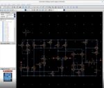
The big idea at Pulsic is that using their software tool called Animate, an analog IC layout designer can then speed up layout times by 60% over traditional, manual layout approaches. In the webinar you’ll see how the Pulsic approach starts within the traditional Virtuoso schematic environment, but with one additional window called Animate Preview activated.

The magic sauce at Pulsic is that their software analyzes the circuit topology from the Virtuoso schematic, identifies analog specific patterns like differential pairs and current mirrors, then automatically generates an IC layout while keeping track of analog IC layout issues like transistor grouping and transistor matching. From what I saw, these new concepts go way beyond earlier methodologies like Schematic Driven Layout (SDL), because there is more embedded intelligence going on with the Animate approach. No longer does the circuit designer have to meticulously mark-up and annotate the schematic with constraints about matching and pairing for the IC layout designer to interpret and hopefully implement correctly, as Animate does this inferencing under the hood.

The IC layout designer is the primary user of Animate, and with this new methodology they can get to a first layout quite rapidly, literally within seconds using their favorite editor, like Virtuoso Layout, seeing all of the sized transistors, Pcells and guard ring structures. High-level IC layout changes are best tweaked in the Animate tool, while low-level layout changes are best implemented in the traditional layout editor. Here’s an idea of how many high-level layout options you can simply choose from a selected set of transistors within Animate:

Another way to use Animate is to select schematic transistors and then add your own desired layout constraints, like how many rows each transistor implementation should occupy.

There’s even a floor plan editor in Animate, that allows an experienced layout designer to rapidly move groups of transistors at one time, achieving a more optimized layout with less interconnect congestion and better matching properties.

Summary

So, is analog IC layout 100% push-button automated like digital place and route? No, you still need to have an experienced layout designer operating automation tools like Animate from Pulsic, in order to achieve optimal, robust layouts, in record time. The REPLAY really gives you an idea of how this Animate methodology with higher-level layout operations complements detailed IC layout with traditional tools.

Related Blogs


CDC for MBIST: Who Knew?

CDC for MBIST: Who Knew?
by Bernard Murphy on 11-09-2021 at 6:00 am

CDC for MBIST

Now and again, I enjoy circling back to a topic on which I spent a good deal of time back in my Atrenta days – clock domain crossing analysis (CDC). This is an area that still has opportunity to surprise me at least, in this case looking at CDC analysis around MBIST logic. CDC for MBIST might seem strange. Isn’t everything in test mode synchronous with a single clock? Not quite. JTAG runs on an independent and relatively slow clock whereas MBIST runs on a system speed clock. On the first day of Synopsys Verification Day 2021, Wesley Lee of Samsung gave a nice overview on the details of this unique application of CDC analysis.

Who cares?

CDC is for functional mode problems surely. Who cares if a synchronization error occurs in MBIST testing? Samsung does and good for them. MBIST isn’t just for bring-up testing. High safety level auto electronics now launch periodic inflight testing to check all critical blocks are functioning correctly. MBIST testing would be included in that checklist, but it wouldn’t be very useful if it might be susceptible to synchronization errors. Best case it reports an error on a good memory and your car keeps demanding it be taken in for service. Worst case it fails to report an error on a bad memory…

What’s special about MBIST CDC?

First, Samsung do before and after CDC analyses. “Before” is with master and slave TAP controllers and connections inserted, though with JTAG disabled and without MBIST controllers. “After” is with JTAG enabled and MBIST controllers inserted. Wesley’s rationale for this is that the MBIST logic alone represents a significant addition to the rest of the design. He wants first to flush out problems without MBIST to simplify analysis when MBIST is added.

He mentioned finding value particularly in Machine Learning-based analysis for clustering violations around common root-causes. I remember the early days of combing through thousands of violations, trying to figure out where they all came from. The ML extensions represent a **huge** advance.

Exception analysis

The thing that really stood out for me in Wesley’s talk was optimization of the analysis through quasi static assignments and other constraints. You can be slapdash with these assignments in CDC, but Wesley’s approach is very surgical.

In functional mode, the JTAG interface is obviously static, whereas in MBIST mode, some interface signals can be case analyzed (set to a fixed value). Some signals from slave TAPs to the corresponding MBIST controllers counts as effectively synchronized because they are qualified by an enable signal which is synchronized.

More interesting still, some MBIST signals interface with the slave TAP controller without synchronization or qualification of any kind. You should understand that this design uses a 3rd-party MBIST controller, so Wesley can’t just walk down the hall to ask why. They needed a meeting or two with the supplier to figure out why they considered this approach OK. The supplier explained that the controller knows how long its analysis will take. It counts for that number of clocks, plus a margin and then transmits these signals. In effect the signals are quasi-static until the slave TAP reads these values and again quasi static beyond that point.

Wesley’s summed up by saying that sometimes you must understand programming sequences. Not all quasi-static assignments have no-brainer rationales. Sometimes you really need to dig into the functionality.

A very interesting review of CDC analysis around MBIST. You can learn more from the recorded session. Wesley’s gave his talk on Day 1.

Also Read:

AI and ML for Sanity Regressions

IBM and HPE Keynotes at Synopsys Verification Day

Reliability Analysis for Mission-Critical IC design


A Packet-Based Approach for Optimal Neural Network Acceleration

A Packet-Based Approach for Optimal Neural Network Acceleration
by Kalar Rajendiran on 11-08-2021 at 10:00 am

6 Optimal Work Unit Designed for DLA

The Linley Group held its Fall Processor Conference 2021 last week. There were a number of very informative talks from various companies updating the audience on the latest research and development work happening in the industry. The presentations were categorized as per their focus, under eight different sessions. The sessions topics were, Applying Programmable Logic to AI Inference, SoC Design, Edge-AI Software, High-Performance Processors, Low-Power Sensing & AI, Server Acceleration, Edge-AI Processing, High-Performance Processor Design.

Edge-AI processing has been garnering a lot of attention over the recent years and hardware accelerators are being designed-in for this important function. One of the presentations within the Edge-AI Processing session was titled “A Packet-based Approach for Optimal Neural Network Acceleration.” The talk was given by Sharad Chole, Co-Founder and Chief Scientist at Expedera, Inc. Sharad makes a strong case for rethinking implementation of Deep Learning Acceleration (DLA). He presents details of Expedera’s DLA platform and how their packet-based accelerator solution enables optimal results. The following is what I gathered from Expedera’s presentation at the conference.

Market Needs

As fast as the market for edge processing is growing, the performance, power and cost requirements of these applications are also getting increasingly demanding. And AI adoption is pushing processing requirement more toward data manipulation rather than general purpose computing. Deep learning models are fast evolving and an ideal accelerator solution optimizes for many different metrics. Hardware accelerator solutions are being sought after to meet the needs of a growing number of consumer and commercial applications.

Inefficiencies in Neural Network Acceleration

Traditional DLA architectures breakdown neural networks (NN) into granular work units for execution. This approach directly limits performance as existing hardware cannot directly execute higher level functions. While CPU-centric solutions may offer flexibility and potential for optimization, they are non-deterministic and fall short on power efficiency. Interpreter-centric solutions offer layer-level reordering optimization but they require large amounts of on-chip memory, a resource that is precious, particularly in edge devices. Benchmark studies indicate that current AI inference SoCs are performing at 20-40% utilization levels. Efforts to improve performance efficiency often prove counterproductive. For example, increasing throughput with larger batch sizes adversely impacts latency. Improving accuracy with compute precision consumes additional bandwidth and power. Targeting higher system utilization increases software complexity. Deploying trained models using these solutions is cumbersome and time-consuming.

Packet-based Approach for NN Acceleration

To overcome the above inefficiencies, Expedera breaks down NN into optimal work units designed for its DLA, calling them packets. Packets in this context are defined as contiguous fragments of NN layers, along with the respective contexts and dependencies. Packets allow for simple compilation of the neural network into packet streams. The packet streams are executed natively on the Expedera DLA platform.

This packet-based approach renders lots of benefits. The design is simplified and performance is improved. The amount of memory and bandwidth requirements are drastically reduced, allowing DLA hardware to be better right-sized. For example, using a popular benchmark the packet-based approach was shown to reduce DDR transfers by more than 5x compared to layer-based processing. The packet-based approach provided cascading benefits including fewer intermediate data movement, higher throughput, lower system power requirement, and reduced BOM cost.

Expedera’s Solutions

As edge processing workloads evolve, applications need to support multiple models and increasing data rates. And SoCs need to support a mix of applications. The packet-based DLA codesign approach delivers a high-performance solution that is scalable and power efficient. It allows for parallel use of independent resources. Expedera DLA enables zero-cost context switching and provides for multi-tenant application support.

Expedera’s Compiler achieves out-of-the-box high performance. Its Estimator allows for right-sizing the DLA hardware. The Runtime scheduler orchestrates the best sequence of NN segments based on application requirements, enabling seamless deployments.

Benefits of Expedera’s DLA Platform

  • Best performance per Watt
  • Smaller designs
  • Lower power
  • Determinism

A Deterministic Advantage

As the packets are complete with context and dependencies, the packet-stream approach guarantees cycle-accurate DLA performance. Packet-DLA codesign enables deterministic and high performant compilation. Exact execution cycles as well as memory and bandwidth needs are known ahead of time, leading to a deterministic execution. This is a prized advantage with edge applications where low and consistent latency is important.

Summary

In a nutshell, Expedera’s customers can easily and rapidly implement their AI SoC designs for edge processing to deliver optimal deep learning acceleration for their applications. Achieving optimal AI performance calls for solving a multi-dimensional problem. With a comprehensive SDK built on Apache TVM, Expedera accelerator IP platform enables ideal accelerator configuration selection, accurate NN quantization and seamless deployment.

To learn about how Expedera’s DLA IP performance compares against other DLA IP solutions, refer to a whitepaper published by the Linley Group. The whitepaper titled “Expedera Redefines AI Acceleration for the Edge” can be downloaded from here.

** Apache TVM is an open-source machine learning compiler framework for CPUs, GPUs, and machine learning accelerators.

Also read:

CEO Interview: Da Chaung of Expedera

Expedera Wiki


S2C EDA Delivers on Plan to Scale-Up FPGA Prototyping Platforms to Billions of Gates

S2C EDA Delivers on Plan to Scale-Up FPGA Prototyping Platforms to Billions of Gates
by Daniel Nenni on 11-08-2021 at 6:00 am

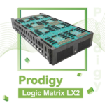
S2C EDA Prodigy Logix Matrix LX2

S2C has been a global leader in FPGA prototyping for nearly two decades now, and its FPGA prototyping platforms have closely tracked the availability of the latest FPGAs – including the latest FPGAs from both Xilinx and Intel.  And they are definitely delivering on the promise to advance their prototyping solutions for hyperscale design prototyping – scaling-up prototyping platform capacities and capabilities to support multi-billion gate designs.

Looking back to early 4Q 2020, S2C announced support for the then-new Xilinx VU19P UltraScale+ FPGAs, offering single, dual, and quad FPGA prototyping platforms.  Then, in December of 2020, S2C followed-up with an announcement of its high-density Prodigy Logic Matrix family of prototyping platforms with 8 FPGAs per Logic Matrix, 8 Logic Matrix per single server rack (64 FPGAs), and the connection of multiple server racks together.  The first iterations of Logic Matrix were delivered with Xilinx VU440 FPGAs (dubbed the LX1) to early customers who couldn’t wait for the VU19P version (dubbed the LX2).

Now, S2C is stepping up its Logic Matrix game with the LX2, which jumps prototyping usable gate capacity by 60% over than the VU440 version!  More usable gates per FPGA means fewer FPGAs, fewer FPGA interconnects, and higher performance for the same prototyped design.  With an estimated gate capacity of 392 million gates per LX2, a fully populated standard server rack with 8 LX2’s enables an estimated prototyping capacity of over 3 billion ASIC gates!

Figure 1: Prodigy Logic Matrix LX2

Prodigy Logic Matrix Family
LX1 LX2
FPGA XCVU440 XCVU19P
Estimated ASIC Gates (M) 240 392
Number of FPGAs 8 8
System Logic Cells (K) 44,328 71,504
FPGA Memory (Mb) 709 1,327.2
DSP Slices 23,040 30,720
External User I/Os 9,216 10,368
 SerDes Transceivers 384 GTH 640 GTY
Prodigy Connectors 64 72
PGT Connectors 8 0
Transceiver Connectors 80 MSAS each with 4 GTH + 8 IOs 160 MCIO each with 4 GTY + 8 IOs
SerDes Performance 16 Gbps 28 Gbps

Figure 2: Logic Matrix Family

Flexible, high-speed interconnect is key to high-density FPGA prototyping, and Logic Matrix supports a hierarchical, 3-level interconnect strategy: ShortBridge for interconnect between neighboring FPGAs; SysLink for high-bandwidth FPGA cable interconnect, and TransLink for longer distance FPGA SerDes interconnect over MCIO cables.  To simplify FPGA interconnect and maximize the value of TransLink, S2C’s partitioning flow supports Xilinx’s newly introduced High-Speed Transceiver Pin Multiplexing (HSTPM), simplifying cycle-accurate signal transfer, pin-multiplexing, and low-latency SerDes FPGA connectivity.

To minimize time-to-prototyping, and maximize prototyping productivity, S2C’s other prototyping productivity tools are designed with Logic Matrix in mind, including Player Pro Runtime software – and add-on S2C prototyping tools including ProtoBridge, MDM Pro, and S2C’s Prototype Ready IP.

Player Pro Runtime software is included with LX2, providing convenient features such as advanced clock management, integrated self-test, automatic board detection, I/O voltage programming, multiple FPGA downloads, and remote system monitoring and management.  Also included is AXEVision, a built-in AXI-over-Ethernet debugging tool to simplify remote debugging of AXI related designs.

ProtoBridge supports high-throughput data transfers (up to 1GB/s) between the host PC and the LX2 – enabling the transfer of large amounts of software-modeled transactions, video streams, or other test stimulus for system validation.

Figure 3: ProtoBridge

MDM Pro features deep trace debugging with cross-triggers for up to eight FPGAs, multi-FPGA signal trace viewing from a single viewing window, 64GB of external trace waveform storage, trace sampling rates up to 125MHz, and supports trigger state machine languages for complex trace captures requirements.

Figure 4: MDM Pro

S2C’s also offers a rich library of Prototype Ready IP for the LX2 – plug-and-play Daughter Cards – that speeds the creation of the prototyping environment around the FPGA prototype.

Figure 5: Prototype Ready IP Daughter Cards

Prodigy Logic Matrix LX2 is available now.  For more information, please contact your local S2C sales representative, or visit www.s2ceda.com.

Also Read:

Successful SoC Debug with FPGA Prototyping – It’s Really All About Planning and Good Judgement

S2C FPGA Prototyping solutions help accelerate 3D visual AI chip

Prototypical II PDF is now available!


Thick Data vs. Big Data

Thick Data vs. Big Data
by Ahmed Banafa on 11-07-2021 at 10:00 am

Thick Data vs. Big Data

One of the challenges facing businesses in post-COVID-19 world is the fact that consumer behavior won’t go back to pre-pandemic norms. Consumers will purchase more goods and services online, and increasing numbers of people will work remotely just to mention few major changes . As companies begin to navigate the post-COVID-19 world as economies slowly begin to reopen, the use of data analytics tools will be extremely valuable in helping them adapt to these new trends. Data analytics tools will be particularly useful for detecting new purchasing patterns and delivering a greater personalized experience to customers, in addition to better understanding of consumers new behavior.

However, many companies are still dealing with obstacles to successful big data projects. Across industries, the adoption of big data initiatives is way up. Spending has increased, and the vast majority of companies using big data expect return on investment. Nevertheless, companies still cite a lack of visibility into processes and information as a primary big data pain point. Modeling customer segments accurately can be impossible for businesses who don’t understand why, how and when their customers decide to make purchases for example.

To tackle this pain point companies might need to consider an alternative to big data, namely thick data, it’s helpful to define both terms, Big Data vs. Thick Data.

Big Data is large and complex unstructured data, defined by 3 V’s; Volume, with big data, you’ll have to process high volumes of low-density, unstructured data. This can be data of unknown value, such as Facebook actions, Twitter data feeds, clickstreams on a web page or a mobile app, or sensor-enabled equipment. For some organizations, this might be tens of terabytes of data. For others, it may be hundreds of petabytes. Velocity: is the fast rate at which data is received and acted on. Variety refers to the many types of data that are available. Unstructured and semi-structured data types, such as text, audio, and video, require additional preprocessing to derive meaning and support metadata.

Thick Data is about a complex range of primary and secondary research approaches, including surveys, questionnaires, focus groups, interviews, journals, videos and so on. It’s the result of the collaboration between data scientists and anthropologists working together to make sense of large amounts of data. Together, they analyze data, looking for qualitative information like insights, preferences, motivations and reasons for behaviors. At its core, thick data is qualitative data (like observations, feelings, reactions) that provides insights into consumers’ everyday emotional lives. Because thick data aims to uncover people’s emotions, stories, and models of the world they live in, it can be difficult to quantify.


Comparison of Big Data, and Thick Data

  • Big Data is quantitative, while Thick Data is qualitative.
  • Big Data produces so much information that it needs something more to bridge and/or reveal knowledge gaps. Thick Data uncovers the meaning behind Big Data visualization and analysis.
  • Big Data reveals insights with a particular range of data points, while Thick Data reveals the social context of and connections between data points.
  • Big Data delivers numbers; Thick Data delivers stories.
  • Big data relies on AI/Machine Learning; Thick Data relies on human learning.

Thick Data can be a top-notch differentiator, helping businesses uncover the kinds of insights they sometime hope to achieve from big data alone. It can help businesses look at the big picture and put all the different stories together, while embracing the differences between each medium and using them to pull out interesting themes and contrasts. Without a counterbalance the risk in a Big Data world is that organizations and individuals start making decisions and optimizing performance for metrics—metrics that are derived from algorithms, and in this whole optimization process, people, stories, actual experiences, are all but forgotten.

If the big tech companies of Silicon Valley really want to “understand the world” they need to capture both its (big data) quantities and its (thick data) qualities. Unfortunately, gathering the latter requires that instead of just ‘seeing the world through Google Glass’ (or in the case of Facebook, Virtual Reality) they leave the computers behind and experience the world first hand. There are two key reasons why:

  • To Understand People, You Need to Understand Their Context
  • Most of ‘the World’ Is Background Knowledge

Rather than seeking to understand us simply based on what we do as in the case of big data, thick data seeks to understand us in terms of how we relate to the many different worlds we inhabit.

Only by understanding our worlds can anyone really understand “the world” as a whole, which is precisely what companies like Google and Facebook say they want to do. To “understand the world” you need to capture both its (big data) quantities and its (thick data) qualities.

In fact, companies that rely too much on the numbers, graphs and factoids of Big Data risk insulating themselves from the rich, qualitative reality of their customers’ everyday lives. They can lose the ability to imagine and intuit how the world—and their own businesses—might be evolving. By outsourcing our thinking to Big Data, our ability to make sense of the world by careful observation begins to wither, just as you miss the feel and texture of a new city by navigating it only with the help of a GPS.

Successful companies and executives work to understand the emotional, even visceral context in which people encounter their product or service, and they are able to adapt when circumstances change. They are able to use what we like to call Thick Data which comprises the human element of Big Data.

One promising technology that can give us the best of both worlds (Big Data and Thick Data) is affective computing.

Affective computing is the study and development of systems and devices that can recognize, interpret, process, and simulate human affects. It is an interdisciplinary field spanning computer science, psychology, and cognitive science. While the origins of the field may be traced as far back as to early philosophical enquiries into emotion (“affect” is, basically, a synonym for “emotion.”), the more modern branch of computer science originated with Rosalind Picard’s 1995 paper on affective computing. A motivation for the research is the ability to simulate empathy. The machine should interpret the emotional state of humans and adapt its behavior to them, giving an appropriate response for those emotions.

Using affective computing algorithms in gathering and processing data will make the data more human and show both sides of data: quantitative and qualitative.

Ahmed Banafa, Author the Books:

Secure and Smart Internet of Things (IoT) Using Blockchain and AI

Blockchain Technology and Applications

Read more articles at: Prof. Banafa website

References

https://www.linkedin.com/pulse/8-key-tech-trends-post-covid-19-world-ahmed-banafa/

https://www.bdex.com/thick-data-why-marketers-must-understand-why-people-behave-the-way-they-do/

https://www.usertesting.com/blog/thick-data-vs-big-data

https://www.oracle.com/in/big-data/what-is-big-data/

https://www.cognizant.com/us/en/glossary/thick-data

http://www.brandwatch.com/2014/04/what-is-thick-data-and-why-should-you-use-it/

http://ethnographymatters.net/2013/05/13/big-data-needs-thick-data/

http://www.wired.com/2014/04/your-big-data-is-worthless-if-you-dont-bring-it-into-the-real-world/

http://www.big-dataforum.com/238/big-data-how-about-%E2%80%9Cthick-data%E2%80%9D-%E2%80%94-or-did-we-just-create-another-haystack

http://blog.marketresearch.com/thick-data-and-market-research-understanding-your-customers

http://www.wired.com/2013/03/clive-thompson-2104/


GM’s Postcard from Fantasyland

GM’s Postcard from Fantasyland
by Roger C. Lanctot on 11-07-2021 at 6:00 am

GMs Postcard from Fantasyland

In the midst of what may well be the greatest electric vehicle debacle of the nascent EV era, General Motors put on a happy face telling investors two weeks ago that all things EV and autonomous were going swimmingly to plan with gumdrops and sugar plums coming on the road ahead. GM claimed before-end-of-year availability for the absurd 1,000-horse-power, 4.5-ton Hummer EV and late 2022 availability for the Silverado EV.

Meanwhile, the General is facing a $1.9B financial hit* from buying back (or repairing) 141,000 Bolt EVs – a reality that GM CEO Mary Barra skirted in a Fox Business interview by referring to “cell replacements” for Bolt EV owners. Those comments clearly sidestepped the reality of a growing number of Bolt owners seeking outright buybacks of their cars after being told not to park them in their garages and discovering their vehicles were also prohibited from some public covered parking facilities including those at Detroit Metropolitan Airport. (*Worth noting battery supplier has accepted responsibility for the battery failure and is compensating GM to the tune of $1.9B – all the more reason for GM to accelerate customer compensation.)

Adding to the fanciful technology outlook painted for GM investors was a sunny forecast for millions of self-driving Origin robotaxis arriving in the market within a few short years – illustrated by a graph showing an exponential adoption rate. Based on a single deployment in a confined area in San Francisco this outlook is optimistic in the extreme.

Sadly, the exaggeration and chest-thumping on behalf of Cruise Automation’s self-driving efforts over-shadowed the more significant technological advances coming from GM’s own tech labs in Warren, Mich. What really deserved attention at the event was GM’s success in bringing semi-automated driving in the form of Super Cruise to the market without a hitch or whiff of a mishap or negative headline. In fact, the technology is on the cusp of a major global rollout reflecting impressive progress.

This technological achievement was worthy of glorification – not the billion-dollar boondoggle of Cruise, which represents a dumpster fire of a cash burn with little yet to show in terms of adoption, technological achievement, or even a compelling consumer application. Even Waymo’s modest progress is massively superior to Cruise’s gains – and Intel’s Mobileye continues to roll out its own robotaxi prototyping endeavors in groundbreaking launches and creative partnerships in New York, Munich, and elsewhere around the world.

But automated driving and semi-automated driving aside, GM’s EV situation is in the midst of a massive crisis. GM’s Barra claims the company is not intimidated by Tesla and is prepared to take the upstart EV maker on – but GM has more than Tesla to be concerned about. Hyundai, Kia, Ford Motor Company, and, now, Porsche are all in play with varying degrees of success.

An EV customer considering his or her options will be hard pressed to overlook the fact that Tesla has the strongest track record in the EV sector – with vehicles having demonstrated their ability to endure a wide range of operating conditions without catastrophic failures of the sort experienced by a handful of Bolt EVs (so far). Price is certainly a primary consideration – and incentives – but durability and reputation matter.

In the aforementioned Fox interview, the Fox correspondent noted that she was a recent convert from Lexus to Tesla and praised Tesla’s direct response when she had a tire inflation issue. In other words, GM is not simply competing on price or technology – it is also being forced to compete on customer service, and failing.

The Bolt EV debacle is something GM is trying to sweep under the rug – not unlike the ignition switch crisis which lingers on in litigation and incomplete recalls. Like the ignition switch recall and litigation, GM is taking on the Bolt EV failure on a case by case basis, resulting in a lingering stank on the GM brand. One begins to wonder whether anyone in GM’s warranty department has ever removed a band-aid before.

In essence, with the Bolt EV failure GM has wasted all or a substantial portion of its EV tax credits, it has massively undermined its own EV credibility in the midst of an announced $35B EV investment program, and it has minted thousands of new Tesla buyers – customers fed up with waiting for GM to get it right. Remember, GM’s journey began with the EV-1 that customers loved but that GM called back and crushed; and followed up with the extended range EV Volt, which customers loved but that GM threw overboard in favor of the Bolt.

GM promises that all will be right in a world built upon the new Ultium battery foundation. For that to happen, GM must A) buy back all 141,000 Bolts and B) offer a life-time warranty on any Ultium battery vehicles. Nothing less will restore long lost luster to the GM brand and prop up the customer retention necessary to the brand’s future. Happy talk, denial, and tap dancing will not suffice.