You are currently viewing SemiWiki as a guest which gives you limited access to the site. To view blog comments and experience other SemiWiki features you must be a registered member. Registration is fast, simple, and absolutely free so please, join our community today!
Analog Bits, the industry’s leading provider of low-power mixed-signal IP solutions will be demonstrating several IP’s in TSMC advanced nodes at DAC. Analog Bits is also a long time DAC supporter and very active in the semiconductor and on SemiWiki, absolutely. Great company!
As power management and energy efficiency is getting critical for AI and ML chips, Analog Bits has developed several novel IP’s in advanced processes to better monitor and manage power. The newest LDO IP, Power supply droop detectors, Embedded Clock LC PLL’s in TSMC N3P process and will be demonstrating working silicon results from test chips at their booth at DAC. Additionally there will be demonstration is showcasing Analog Bits’ industry leading portfolio of Mixed Signal IP in advanced 3nm, 4nm, 5nm, and Automotive processes.
As more designs are going to multicore architectures, managing power for all those cores becomes important. The new LDO macro can be scaled, arrayed, and shared adjacent to CPU cores and to simultaneously monitor power supply health. With Analog Bits’ detector macros, power can be balanced in real time. Mahesh Tirupattur, Executive Vice President at Analog Bits said, “It is like PLL’s that maintain clocking stability we have are now able to offer IP’s to maintain power integrity in real time.”
Features of the new LDO macro include:
Integrated voltage reference for precision stand-alone operation
Easy to integrate, use, and configure with no additional components or special power requirements
Scalable for multiple output currents
Programmable output level
Trimmable
Implemented with Analog Bits’ proprietary architecture
Requires no additional on-chip macros, minimizing power consumption
Analog Bits’ Droop Detector addresses SoC power supply and other voltage droop monitoring needs. The Droop Detector macro includes an internal bandgap style voltage reference circuit which is used as a trimmed reference to compare the sampled input voltage against.
The part is synchronous with latched output. Only when the monitored voltage input has exceeded a user-selected voltage level will the Droop Detector output signal indicate that a violation is detected.
In gate-all-around architectures there will be only one gate oxide thickness available to support the core voltage of the chip. Other oxide thicknesses to support higher voltages are simply no longer available. In this scenario, the Pinless Technology invented by Analog Bits will become even more critical to migrate below 3nm as all of the pinless IP will work directly from the core voltage.
The Pinless PVT Sensor at TSMC N5 and N3 provides full analog process, voltage, and temperature measurements with no external pins access required by running off the standard core power supply. This approach delivers many benefits, including:
No on-chip routing of the analog power supply
No chip bumps
No package traces or pins
No PCB power filters
As the electronic content in automobiles continues to increase, the need for a complete library of IPs that meet the stringent requirements of this operating environment become more important. Analog Bits will showcase a wide range of IP that meets automotive requirements on the TSMC N5A process.
Analog Bits’ Wide Range PLL addresses a large portfolio of applications, ranging from simple clock de-skew and non-integer clock multiplication to programmable clock synthesis for multi-clock generation. This IP is designed for AEC-Q100 Automotive Grade 2 operation.
The PLL macro is implemented in Analog Bits’ proprietary architecture that uses core and IO devices. In order to minimize noise coupling and maximize ease of use, the PLL incorporates a proprietary ESD structure, which is proven in several generations of processes. Eliminating bandgaps and integrating all on-chip components such as capacitors and ESD structure helps the jitter performance significantly and reduces stand-by power.
Dan is joined by Ninad Huilgol, founder and CEO at Innergy Systems. Ninad has extensive experience in design verification of ultra low-power mobile SoCs. Previously, he has worked in senior engineering management at various semiconductor companies such as Broadcom and Synopsys. He has multiple power- and design-related patents, trade secrets and is the recipient of a Synopsys Inventor award.
Ninad discusses the shortcomings of current power analysis techniques and explains how Innergy Systems addresses these challenges with a breakthrough approach to power analysis that is fast and accurate. The result is extensive and efficient “what if” analysis to deliver an optimized power profile.
The views, thoughts, and opinions expressed in these podcasts belong solely to the speaker, and not to the speaker’s employer, organization, committee or any other group or individual.
The Silicon Catalyst-Arm start-up contest winners were announced this week. This was the first contest of its kind so there was quite a bit of excitement. SemiWiki has worked closely with Silicon Catalyst for the past four years which has been quite the journey. Out of the one hundred plus companies SemiWiki has worked with over that last 13 years, Silicon Catalyst is the most successful of its kind, absolutely.
The two winners were selected from a large number of applicants. First place and winner of $250,000 of Arm technology credit is Agate Sensors from Finland.Agate Sensors is developing hyper-spectral sensors for the Wearables and Mobile Devices markets. Here is the pitch deck they submitted:
The runner-up company is Smartkosh Technologies from Indiawinning $150,000 of Arm technology credit .Smartkosh is developing Battery Management Solutions. Here is the Smartkosh pitch-deck:
The contest awards include commercial, technical and marketing support from Arm and Silicon Catalyst. The winners will receive Arm technology credit that can be applied to commercial tape out licensing fees.
Both companies will also receive: Cost-free Arm Design Review with Arm’s experienced support team, Investor pitch review and preparation support by Silicon Catalyst, and an opportunity to present to the Silicon Catalyst Angels group and their investment syndication network.
The contest was open to eligible early-stage startups that are part of, or considering to be part of, Arm Flexible Access for Startups, which provides no-cost easy access to an extensive design portfolio, free tools, training and support, and a $0 license fee to produce prototypes.
The CEO of Silicon Catalyst is a friend, former coworker, and experienced semiconductor entrepreneur:
Pete Rodriguez, CEO of Silicon Catalyst, stated, “Leveraging our strong collaboration with Arm as both a Silicon Catalyst Strategic Partner and an In-Kind Partner, we launched a global contest last year for early-stage entrepreneurial teams. The aim was to offer valuable commercial and technical support from Arm. Continuing now in our joint contest’s second year, the applicant companies showcased a remarkable variety of technologies and application targets, along with geographic diversity. The enthusiastic response to this contest highlighted the extensive range of products within Arm’s portfolio, underscoring the significant value of the Arm Flexible Access for Startups program. The applicants presented some of the most exciting emerging applications utilizing Arm® technologies, including quantum computing, consumer products, massively parallel AI, cryptography, and wireless communications. I congratulate the teams at Agate Sensors and Smartkosh Technologies.”
Silicon Catalyst’s mission is to help semiconductor startups succeed in all aspects of business. Early-stage companies may be eligible to receive initial seed funding from Silicon Catalyst Angels and other partners. Companies that are accepted to participate in Luminate and Silicon Catalyst accelerator programs concurrently will receive $100,000 in funding at the start of programming and a chance to compete for up to $2M.
Incubated companies will be eligible to apply to Silicon Catalyst Angels for access to additional funding. Apply now!
Bottom line: Having done start-ups for most of my 40 year semiconductor career I can tell you first hand how challenging AND rewarding it is. If you’re a semiconductor startup in its early stages, seriously consider how Silicon Catalyst and the Arm Flexible Access for Startups can ensure your success.
Introduction of 2.5D and 3D multi-die based products are helping extend the boundaries of Moore’s Law, overcoming limitations in speed and capacity for high-end computational tasks. In spite of its critical function within the 3DIC paradigm, the interposer die’s role and related challenges are often neither fully comprehended nor appreciated. A recent webinar hosted by Synopsys included presenters from AMD sharing their experiences in detail on a comprehensive design flow, which is based on Synopsys’ 3DIC Compiler platform, that addresses opportunities across floorplanning, construction, extraction, and signoff. The MI300X platform is designed to deliver exceptional performance for AI and HPC. It uses state-of-the-art die stacking and chiplet technology in a multi-die architecture that enables dense compute and high bandwidth memory integration.
Evolution of Packaging Technology
Packaging technology has significantly evolved to meet the increasing complexity of multi-die designs. Initially, organic substrates supported around 100 I/O connections per square millimeter, but modern techniques like hybrid bonding now enable over 100 million I/O connections per square millimeter. This evolution enhances integration and communication between dies, boosting overall system performance and enabling more compact and efficient designs essential for high-performance computing. The shift from organic substrates to advanced hybrid bonding marks a major advancement in supporting multi-die architectures, pushing the limits of speed, capacity, and integration.
Key technologies include:
C4 (Controlled Collapse Chip Connection): Used for pitches greater than 75 µm, suitable for applications with larger pitch sizes.
Microbumps: Provide finer pitches around 15 µm, enabling higher interconnect density for more integrated and compact designs.
Hybrid Cu (Copper) Bonding: Allows extremely tight pitches as small as 1 µm, offering high interconnect density and improved electrical and thermal performance.
These technologies facilitate the stacking of different chip types within a single package, supporting the development of powerful, efficient, and compact electronic systems.
The 3DIC Device Ecosystem
The 3DIC device ecosystem includes a variety of design styles and technologies such as CoWoS-S/R/L, InFO_oS, and SolC_H, each requiring different routing standards like HBM, and UCle. With such an array of technologies and design styles available for 3DIC integration, there come many challenges.
Challenges Faced
Floorplanning complexities arise from manual calculations and a lack of automation for bump mapping between dies, complicated by the risk introduced by alterations prior to 3D assembly. Construction faces a dilemma between slow manual custom layout and auto-routing tools ill-equipped for 3DIC-specific challenges, necessitating meticulous constraint management. Incorporating a 3D solver becomes imperative here for addressing complex routing issues effectively. Extraction struggles with standard RC methods to capture intricate package-style constructs and mitigate parasitic inductance on critical nets, necessitating the use of a Full Wave 3D solver for accurate RLC extraction, despite its labor-intensive nature. Finally, signoff encounters hurdles in static timing analysis (STA) due to the lack of inductance support, coupled with manual and non-scalable RLC extraction processes. This calls for integration of 3D solvers to model and analyze parasitic effects accurately within 3DIC architectures. These challenges underscore the critical need for innovative solutions to advance semiconductor design efficiency and reliability.
Advancing 3DIC Solutions
The focus should be on automation, smarter functionality, faster results, and reduced human intervention. Key strategies should include developing advanced algorithms for automating design tasks, integrating machine learning for intelligent suggestions, implementing parallel processing for speed, and optimizing workflows. Additionally, adopting constraint-aware design methodologies and automatic ECO generation will minimize manual intervention. Continuous improvement through feedback loops and agile development, along with enhanced verification and reliability-aware design techniques, will ensure high-quality and reliable products.
Synopsys 3DIC Compiler Platform
The Synopsys 3DIC Compiler platform and related tools address the challenges discussed above. The platform offers a simple command to mirror bumps between dies and automatically accounts for rotations, flips, optical shrinks and other complications. It enables die-to-die signal routing to support silicon-style 90-degree and 45-degree routing as well as PKG-style routing involving teardrops, degassing, etc. Matched-length, matched-pattern routing characterisitc of HBM subsystems are well supported with shielding to ensure signal integrity. Both RC and RLC extraction are supported from within the 3DIC Compiler platform, leaving it to the designer to choose between faster turnaround and best accuracy as appropriate and applicable.
Summary
The Synopsys 3DIC Compiler integrates various design stages and supports diverse technologies. Advanced automation and embedded AI technology enable intelligent routing and predictive analysis, reducing manual efforts. While there is always room for more automation features for 3DIC, the Synopsys 3DIC Compiler platform is a significant leap ahead of current generation solutions.
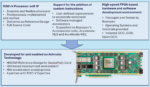
Recently, a partnership between Achronix and Bluespec has been in the news. Bluespec RISC-V processors are available as soft cores in a Speedster®7t FPGA on Achronix’s VectorPath® PCIe development card or in a standalone Speedster7t FPGA. We spoke with executives from Achronix and Bluespec about the impetus for this effort and where it might lead. Industry veterans Nick Ilyadis, VP of Product Planning at Achronix (NI), and Loren Hobbs, VP of Product and Business Development at Bluespec (LH), shared their thoughts.
SW: What brought Achronix and Bluespec together for this partnership?
NI: Several years ago, we searched for a small processor core we could use in our FPGAs to do maintenance, train memory interfaces, and perform other tasks. We found Bluespec had a nice, compact core that would meet our needs, and we licensed it and started working with it. In the process, I became aware of other Bluespec capabilities and the breadth of their CPU core offerings, particularly the ability to create custom instructions for accelerators coupled to cores. There was a natural fit in having a CPU use the FPGA fabric for acceleration in a very tightly coupled manner. Using our 2D network-on-chip (NoC) as a transport mechanism for RISC-V cores, accelerators, memory resources, and PCIe differentiates our solution.
SW: Was it all about the 2D NoC, or were there other Speedster7t FPGA attributes that made this attractive for Bluespec?
LH: We agree – this partnership has been in the making for years and is not just a recent discovery, starting with our MCU core and adding from there. We saw an FPGA with a combination of high-speed memory interfaces, high-speed I/O devices, and high bandwidth across the FPGA fabric with the 2D NoC. There was also the idea of scalable processing with one or more instances of our RISC-V processor cores working with accelerators in a design. The architecture fits together nicely.
SW: Can you describe, maybe by a range, how much of the Speedster7t FPGA area a Bluespec RISC-V core takes?
LH: It’s a range since we have smaller and larger RISC-V cores, and it varies by features included and how much customization is involved. Off the top of my head, a small core would be somewhere from 2 to 4% of the device. On larger cores, with floating point and instruction extensions, we’d be perhaps 8 to 9% of the device. Less than 10% of a device for one core is a good starting point.
SW: Aside from customization capability, how does a Bluespec RISC-V core differ from other RISC-V offerings?
LH: We follow the RISC-V spec closely, including for instruction extensions. High-end processing isn’t our target – we’re more about doing small routines and managing accelerators and I/O, running on bare metal, or using an RTOS such as FreeRTOS, or Linux. We offer a five-stage pipeline and a choice of instruction extensions beyond the basic integer instructions, with options for multiplication (M), atomic (A), and compressed (C) instructions. We also support optional single or double-precision floating-point instructions (F and D). Our key differentiator is tooling to quickly add support for accelerators as custom instructions in a core.
SW: We’ve talked with Achronix before about Speedster7t FPGA applications like automated voice recognition (AVR) and the evolution of SmartNICs into data processing units (DPUs). How do you see RISC-V cores meshing with other IP in an FPGA?
NI: One example is AI/ML inferencing. Neural networks now have tens of thousands of nodes with tens of thousands of interconnects. They are getting so large that they are outgrowing a static implementation in a single FPGA, so the strategy is now breaking up the network into layers and segments, then dynamically loading individual segments, activation functions, and intermediate values. Accelerators can do matrix calculations, sigmoid functions, normalization, or quantization. Subsystems can be spread across the device and connected by our 2D NoC. A RISC-V core orchestrates, firing off a sophisticated state machine initiating accelerators on demand, and high timing accuracy is crucial. Signal processing chains are another example, with DSP blocks and FIR filters for wireless radios including 5G/6G. DPUs also need a processor to handle control plane versus data plane traffic. We’ve even talked to customers about using AI/ML in a DPU to learn how a normal network runs and adjusts when abnormalities appear.
SW: How is the solution delivered to customers?
LH: We provide the RISC-V cores as soft IP in Verilog, and we also provide the open-source toolchains. We include a reference design for initializing the core in software, and we can add a ready-to-run embedded operating system. We also have tooling for developing custom instructions and a software layer for managing accelerators, and it works with high-level synthesis tools or Verilog – it takes most of the hard work out of adding accelerator blocks. Bluespec works closely with our customers, providing “white glove” assistance to bring up the solution. We’ll deliver directly to a customer and help them along the way.
NI: Bluespec has made it easy to load their RISC-V cores onto our VectorPath development card over PCIe as a bitstream. A core can use memory blocks in the Speedster7t FPGA for cache and externally attached memory on the VectorPath card for storing data structures. We’re moving a demo for Bluespec cores on a VectorPath card into our Achronix Virtual Lab (AVL) so customers can access it in the cloud through a VPN to try it out.
SW: What does the ideal customer for this look like?
NI: We’re looking for large telecom infrastructure providers, a networking company, or companies developing AI/ML inference solutions. We’d also like to engage with hyperscalers, especially ones that might have supply chain problems with GPU-based solutions.
LH: We’re in line with that list of traditional customers. We often see larger customers start small, with one team using the design and finding the value, and then it spreads to other teams in the organization. Many of our opportunities come from cross-organizational references.
SW: Is there still some hesitation over the perceived difficulty of programming FPGAs?
NI: Our bitstream loading is simple – we can load from a flash drive, over PCIe, or soon over Ethernet. If a user has software running on a server, our tools help them embed the bitstream inside their operational code and load it. We’re trying to make it as frictionless as possible. With 15 years of tool development under our belt, our code is mature.
LH: Bringing more developers into FPGAs is an age-old question. A top-down architectural understanding of NoCs and interconnected blocks helps, but our combined tools take care of the bottom-up details of programming the FPGA so users can take advantage of the technology.
SW: Finally, where do you see the technology heading?
NI: We’re working on a couple of things – a “baby brother” of the Speedster7t that could still hold small RISC-V cores, and a hardened RISC-V core outside of the fabric so resources are fully available to customers.
LH: Hardening cores enables higher performance, for sure. We also think multicore opportunities will emerge when customers start seeing the possibilities. We’ll continue to align roadmaps and tailor implementations that fit well together.
For more information on Bluespec RISC-V soft cores in Achronix FPGAs:
Peter was running late for two reasons. First, he encountered unexpected heavy traffic and arrived ten minutes late for a crucial meeting with a customer to run a compliance test of his new 6G phone design prototyped on FPGAs. This prototype’s success was pivotal, as it could secure a significant purchase order. Peter had reason to be confident. A rigorous twelve-month verification process, from early RTL stages, through weekly RTL regression testing, to hardware/software integration, software validation, and final system validation, had bolstered his assurance. Second, and more concerning, he was already a week late for his overall schedule which added pressure to the day.
After apologizing for being late, Peter swiftly set up the prototype and connected it to several of his customer’s USB devices. Initially, the demonstration proceeded without a hitch, until they tried the customer’s most important device, a brand-new USB drive. No matter how often he tried to connect, the USB drive stayed invisible causing a chill to run down Peter’s spine. Repeated attempts to recreate the issue by unplugging and plugging the USB cable confirmed the problem persisted, clearly indicating a failure in the design that needed attention back at the factory.
That day, Peter learned an unforgettable lesson about the unpredictability of the real-world environment and the importance of compliance testing under real-life conditions.
Architecture of a Peripheral Interface
Modern system-on-chip (SoC) designs, whether all-in-one systems or sub-systems of a large multi-chip design, communicate with the outside world via a set of peripheral interfaces in the form of IPs. They differ in types and in numbers. Regardless of the type, all share the same architecture that consists of two main components: a controller and a PHY. See figure 1.
Figure 1: Architecture of an Interface IP, including Controller and PHY
The controller, an eminently digital design, implements the communication protocol encompassing the set of functions governing the transmission of data/information between the transmitter and receiver. Today, most interface protocols adhere to industry standards such as PCIe, UCIe, CXL, USB, HDMI, and others.
The PHY, an analog/digital mix-signal design, manages the actual transmission of data to/from the external world which is an analog environment. The PHY deals with voltage, current, power, and other electrical parameters.
Verification of a Peripheral Interface in Stand-Alone Mode
The verification flow of an interface IP, as part of SoC, adheres to the multi-step industry paradigm:
The flow starts with RTL simulation. Since the complexity of an interface IP is limited (one of the most complex protocols such as PCI Express (PCIe) includes less than 10 million equivalent gates), an HDL simulator is adequate for RTL debugging before driver development and system integration begin. Ensuing RTL debug, software driver validation and HW/SW integration are performed with hardware-assisted verification (HAV).
There is one additional step that Peter was missing that is critical for first silicon success: compliance testing. The verification flow of an IP interface finishes with compliance testing to ensure that the design adheres to the rigorous standards set by the compliance body for each protocol. At this stage, a challenge arises because a PHY digital model, as accurate as it may be, does not simulate the analog behavior of a PHY. This limitation hinders comprehensive verification as required by compliance testing. To overcome this hurdle and address the analog aspects, the PHY must be implemented on a test chip.
Interface IP vendors must verify their IPs following the flow just outlined and provide the buyer with confidence that the IP the are buying passed the certification of compliance.
Verification of a Peripheral Interface in an SoC Context
SIDEBAR: Some design teams may interpret the vendor’s IP compliance certification as an excuse to skip their own compliance testing after integrating the IP into their SoC design. This is a risky proposition…
Certifying an interface IP in isolation does not ensure that the integration into the SoC hardware and software is bug free. Everything might appear to function perfectly until system validation in a real-world environment uncovers hidden system bugs. This situation truly tests the IP integration and system design robustness—it’s where “the rubber meets the road.”
Once part of an SoC, an interface IP must operate seamlessly with components that could be designed by the same company or by multiple different companies. It is crucial to verify these interactions to prevent costly issues after the silicon is manufactured.
Peripheral Interface Verification: Benefits of Hardware Emulation vs FPGA Prototyping
HAV platforms fall into one of two categories: hardware emulation or FPGA prototyping, each offering distinct advantages. Emulation platforms are synchronous engines driven by one master clock. The benefit of this attribute is the ability to reliably reproduce error conditions since it allows for quick and straightforward bug tracing and debugging. However, a typical SoC design incorporates various subsystems each operated by independent clocks, which may or may not be synchronized with one another, making the SoC inherently asynchronous.
When a synchronous behavior triggers an error, the emulator can efficiently capture and debug the issue. Yet the predictable nature of these events means there is still a non-zero probability of encountering scenarios in real-life that cannot be duplicated during emulation. Such bugs are more likely to emerge when testing the first silicon samples, where operations are entirely asynchronous.
Conversely, FPGA prototyping is capable of handling purely asynchronous clocks making it an ideal platform for accurately dealing with asynchronous behaviors in a pre-silicon environment. For instance, while in mobile standards such as LTE, 5G, and 6G, there is a central master clock, smartphones require the generation of many different local design clocks, creating a truly asynchronous system. This system cannot be fully verified in an emulation environment. While prototyping can reveal hidden bugs caused by the interaction of asynchronous clocks, tracing and resolving these issues can be time-consuming and frustrating. The only effective method for thorough verification is in a prototyping environment. A SoC prototyping platform should provide the capability of capturing signals at-speed with elaborated trigger mechanism to catch the issue when the system is operating at-speed. A prototyping system also needs enough trace buffer depth to correlate the HW bug that is seen by the SW several milliseconds/seconds after the bug happened.
Emulation and prototyping can be integrated into a verification flow to harness the strengths of each approach. Emulation can identify all bugs that arise in synchronous environments, except for those few that may only manifest through asynchronous behavior. Once these are uncovered, switching to emulation allows for quick and easy tracing and fixing of these issues.
Criticality of Compliance Testing
The importance of IP compliance testing varies among different market segments of the semiconductor industry.
The consumer market is more tolerant if a product failure shows up in the field. If a fault in an HDMI interface of a play-station connected to a TV causes an occasional flickering image, an issue that may be uncovered in compliance testing, the user may elect to overlook the annoyance.
In contrast, an occasional failure in a PCIe interface in the HPC market would lead to a different outcome. Even seemingly minor PCIe interface faults, where occasional transmission bits are dropped, can cripple a data center causing significant financial losses.
Best in class solution for SW development and Compliance Testing
A best-in-class solution enables mapping the controller IP onto a prototyping system and supports a test chip on an extension card that is specifically speed optimized for the prototype system to connect to the real-world interface.
Such a solution is designed to tackle three different verification scenarios:
Out of the Box software driver development
3rd Party Interoperability Testing
Protocol Compliance Testing
Figure 2: Protocol Certification Use Cases (Source: Synopsys)
A real prototyping system must be engineered with two primary objectives in mind: to accelerate SoC software development and validation, and to enable at-speed connection and validation of interfaces. At-speed connectivity is essential for conducting compliance tests of interfaces.
Software also plays a critical role in the system’s overall functionality. A malfunction in the driver configuring the interface can lead to the failure of the entire interface. This highlights the critical need for rigorous validation of both software and hardware elements, including digital and analog components. Comprehensive testing like this is crucial to guarantee that the system operates correctly in real-world conditions.
Conclusion
Peter learned the hard way that skipping compliance testing can result in costly delays. Indeed, if an unidentified design bug slips into manufacturing, the financial repercussions could be severe, involving product recalls, expensive redesign, and millions of dollars in lost revenue in highly competitive markets. This kind of oversight could be catastrophic for a project.
The takeaway is clear: for every SoC project conduct at-speed compliance testing in a real-world environment. You want no chills running down your spine when you go into tape-out!]
Given false starts and OEM strategic retreats you could be forgiven for thinking that the autonomous personal car dream is now a lost cause. But that’s not quite true. While moonshot goals have been scaled back or are running under wraps, applications continue to advance, for adaptive cruise control, collision avoidance, automatic parking and in other areas. Not the original vision of autonomy but stepwise additions to selective assistance and increased safety. Which honestly seems like a better bet for incremental social acceptance than the fully autonomous claim: “trust us, we know what we are doing”. Such advances depend on accurate sensing around the car and radar/lidar plays a big role in that sensing. These types of sensing obviously offer a different kind of imaging requiring a different imaging/recognition pipeline from more familiar vision flows. Here I will focus on radar.
Market trends
According to at one analyst, adaptive cruise control accounted for over 40% of the automotive radar market on 2023 though views differ on the strongest driver (intelligent parking and autonomous emergency braking lead in another review). A CAGR of 35% is expected through 2032 with, interestingly, the fastest growth in Asia Pacific.
Lidar is still a strong competitor to radar, but the gap has narrowed thanks to high-definition imaging radar (HD radar) based on multi-Tx/Rx antennae and beamforming. Existing advantages in all-weather operation and in lower cost now make radar a serious alternative to lidar, as evidenced by product family release from Continental, DENSO, Delphi, NXP, TI, Bosch and others. These include features like 360o fusion, early parking slot detection in crowded parking areas and of course high-resolution imaging radar views in a radar point cloud, enabling high accuracy object detection and classification.
The radar imaging pipeline
Radar pipelines start with radar sensing. Antennae can run from 4×4 (Tx/Rx) for low resolution/long range radar up to 48×64 for high definition/shorter range radars. Next stages are a series of FFTs to decode range and Doppler effects plus beamforming to discriminate directions in 3D. Consider that pulse rates may run to thousands per second, there are multiple antennae, and FFTs may extend to 1k bins. To support up to 50 frames per second for fast response to changes, this level of throughput demands significant signal processing parallelism and dedicated accelerators.
At this point, frames in this streaming data are still an amalgam of reflections from potentially many targets together with noise. The CFAR (constant false alarm rate) stage is where the pipeline discriminates between targets and background. This step is particularly challenging for automotive radar. Traditional radar applications don’t typically expect a lot of targets, but automotive applications can expect up to thousands of targets (other vehicles, pedestrians, obstacles) relatively nearby. The best-known algorithm today, OS-CFAR, handles this task well but is much more complex to implement than more common commercial versions.
Target tracking using both range (X, Y, Z) and Doppler (Vx, Vy, Vz) follows. Using all these parameters in an extended Kalman filter provides maximum discrimination in simultaneously tracking multiple targets, an important consideration for automotive safety, especially in applications like adaptive cruise control. A final AI stage will run classification – is this target a car, a pedestrian, an animal, a barrier?
Building radar pipelines for modern cars
First remember that the days of standalone solutions in cars are long gone. Today, all extended sensing solutions must integrate with OEM preferred architectures, from the edge though zonal controllers to the central controller. Pipelines may be split across these zones. Second remember that while more electronics in the car adds capability, it also increases car cost and decreases range though power consumption, neither of which is a positive for us consumers.
Managing cost, power, and safety/reliability together is a system optimization problem which is arguably why OEMs are now more actively involved in developing or co-developing platform SoC solutions tuned to their architectures. Building around embedded radar IPs from companies like CEVA. CEVA have a unique value proposition in this space, supporting OS-CFAR for example and full 6D extended Kalman filtering. They combine this with their strength in low power DSPs, dedicated extensions for FFTs, beamforming to maximize frames per second throughput and reduce total power, single and half precision floating point support, all accessible through an extensive radar/lidar SDK.
Pretty impressive and I am told the suite also supports lidar pipelines. This is the kind of technology that will help us advance us towards autonomy im easier steps. You can learn more about their Ceva-SensPro Radar solution HERE.
As SoC complexities continue to expand to billions of transistors, the quest for higher levels of design automation also rises. This has led to the adoption of High-Level Synthesis (HLS), using design languages such as C++ and SystemC, which is more productive than traditional RTL design entry methods. In the RTL approach there are formal tools for source code coverage reachability analysis and assertion verification, yet those two formal tools were missing from HLS tool flows, until now. I spoke with David Aerne, Principal Technologist, Catapult Division, Siemens EDA to get an update on their newest HLS and High-Level Verification (HLV) capabilities.
David initially outlined the scope of tools that comprise HLV, with design checking to look for synthesizable code, and static linting with deep formal methods to ensure correctness. For design verification the focus is on functional correctness by using automatic formal property checking of HLS source code along with metrics driven dynamic verification.
These HLV concepts map into two new apps within the Catapult High-Level Verification Flow: Catapult Formal Assert and Catapult Formal CoverCheck.
Catapult Formal Assert
The idea here is to formally prove assertions for function verification by testing design assumptions that are too hard to simulate, and to validate C++ and SystemC for valid ranges, traps and even dead code. Engineers can use assert, assume and cover, while the counter-examples create a C-level testbench.
Catapult Formal CoverCheck
After Catapult Coverage has been enabled during dynamic simulations of your HLS design, you decide if the coverage metrics have been met, and when you need higher coverage, then the Catapult Formal CoverCheck app comes into use. The CoverCheck push-button app formally analyzes coverage holes to bin coverage items into one of three possible categories: reachable, unreachable and undecided with the results predominately being either reachable or unreachable results. Both waivers and counter-examples are produced by CoverCheck. All of the coverage information, including the waivers, are compatible with the Siemens EDA Unified Coverage DataBase (UCDB) which provides the foundation for the Verification Management capabilities integrated within the Catapult HLV flow.
Summary
Designing with C++ and SystemC is more productive than using traditional RTL methods, and now HLV has become even more productive by adding formal property checking and coverage reachability analysis. Siemens EDA has been in the HLS and HLV business for over two decades now, so they have plenty of experience, and adding more apps to HLV just makes the flow more attractive to design and verification engineers.
Verifying at the high-level promises a 100X improvement over RTL methods. Metrics-driven HLV is now possible by using formals methods and coverage analytics, so that your team knows that their design meets the targets. Industries that require Functional Safety (FuSa) and that are following standards like DO-254 and ISO 26262 will certainly benefit from these new HLV apps.
Atomic layer deposition (ALD) is a thin-film deposition method that continues to enable continuous advances in semiconductor device fabrication. Essentially, it involves exposing substrates sequentially to at least two different vapor phase atmospheres in which self-limiting reactions take place on the surface: the first one reacts to deposit a controlled amount of the desired compound as a monolayer, and the second one reacts to modify that deposit and re-create a surface that will again be reactive with the first atmosphere.
Since this process deposits a fixed amount in each of these cycles, simply by choosing the number of these cycles the substrate is exposed to, the thickness of the deposited film can be controlled reproducibly with atomic-scale precision. The self-limiting nature of these reaction steps allows these films to have exceptional uniformity across the substrate on a macro scale, and also along its microscopic topology.
ALD offers several unique advantages that make it a highly valuable technology:
Precise Thickness Control: ALD allows for the deposition of materials at the atomic level, ensuring exceptional uniformity and precise thickness control. This level of control is critical for creating ultra-thin films with consistent properties, making it suitable for a wide range of applications in electronics and photonics.
Conformal Coatings on Complex 3D Surfaces: ALD has the exceptional ability to produce uniform and conformal coatings, even on complex 3D surfaces. This is particularly important for coating high-aspect-ratio features, such as trenches, holes, and intricate 3D structures used in advanced semiconductor devices like Gate-All-Around (GAA) transistors.
Versatility: ALD is versatile in its application across a broad spectrum of materials, from high-k dielectrics like hafnium oxide to various metals and silicon-containing dielectrics. This versatility makes ALD well-suited for addressing diverse film requirements in semiconductor and electronic device manufacturing.
Enhanced Film Performance: Through careful engineering of surface chemistry, ALD enables the deposition of films with improved physical and electrical performance. By designing thermally stable precursors that retain self-limiting surface reactivity at higher temperatures, ALD can produce films with superior properties, contributing to the overall advancement of semiconductor technologies.
The ALD technique has already been used for more than a decade to make both memory and logic chips. The thickness control and uniformity properties of ALD make this technique increasingly important due to the relentless downscaling of the dimensions of these devices as Moore’s Law continues to advance. For one, ALD has been essential to enabling the patterning of structures with optical lithography having repeating dimensions smaller than allowed by optical resolution by a process known as self-aligned multiple patterning. Also, the smaller dimension requires much more precise film thickness control to ensure that all of the billions of circuits in the device have identical electrical properties.
As simple scaling begins to hit practical limits, however, new architectures require that the active structures change orientation and move into the third dimension. For example, logic transistors have already shifted from planar devices to vertical fin structures (so-called FinFETs). Shortly, the active structures will again transform with the fins turned parallel to the surface in the Nanosheet architecture. Now, the deposition of thin films to fully surround such structures must be completely independent of line-of-sight – a task perfectly suited for ALD. Similarly, the two main classes of computer storage memory: NAND flash and DRAM are and will be stacked in a three-dimensional array which requires thin film deposition of films on the extremely high surface area horizontal features.
The challenge of moving into the third dimension cannot be understated. As device structures shrink and become more complex, the need for precision becomes even more critical. With the advent of 3D architectures, such as vertical NAND and 3D DRAM, the industry is moving beyond traditional line-of-sight deposition methods. These new architectures necessitate the deposition of conformal coatings on hidden surfaces, which ALD can achieve due to its self-limiting and surface-controlled reaction mechanism. This capability is paramount as it allows for the creation of uniform films on all surfaces of the complex 3D structures, ensuring reliable device performance.
Central to the success of ALD are the chemical precursors, which have seen significant advancement with the introduction of, for example: aminosilanes, metal amidinates, and alkylamides. For instance, the precursor can be designed to maintain self-limiting reactions at a higher deposition temperature and thereby improve the electrical and mechanical properties of the deposited film. EMD Electronics’ extensive ALD precursor portfolio (See the image of the periodic table which highlights the broad range of elements currently being deposited).
Also, we can rapidly and effectively develop the new precursors to meet the diverse needs of these new architectures by having the ability to perform such thin-film deposition processes in industrially relevant equipment and by designing proprietary device test vehicles to understand how the precursor and process conditions combine to meet the electrical and physical demands of semiconductor devices. Similarly, AI-enhanced molecular modeling enables us to rapidly develop new solutions in line with semiconductor device manufacturer’s technology roadmaps.
Industry Trends and Future Prospects
The pursuit of faster and more scalable deposition methods is an ongoing challenge, reflecting the industry’s ambition to keep pace with the growing demand for advanced materials in mass-production settings. Future trends are poised to not only enhance the ALD technique but potentially set new benchmarks in the engineering of materials at the atomic scale in other areas, including etching and surface treatments, heralding an exciting era for technology manufacturers and their ever-more complex integration schemes.
One emerging area is Area-Selective Deposition: by carefully managing the interaction between the substrate and the precursors through surface modification and chemistry selection, the process allows for highly targeted film growth on specific areas of a substrate while leaving other areas unaffected. Such a process can enable self-aligned features as well as eliminate costly lithography steps.
This is an area we have been increasingly addressing to meet market needs as well as to continue advancing technology for both surface inhibitors and ALD deposition materials.
by Ron Pearlstein,Research & Technology Lead, Semiconductor Solutions Group of EMD Electronics (EMD Electronics is the North American electronics business of Merck KGaA, Darmstadt, Germany)
In the late 1970s, cryptographic history saw the emergence of two seminal algorithms: McEliece and RSA. At that time, quantum threats were theoretical, and the selection criteria for cryptographic algorithms prioritized public key length and execution time, leading to RSA’s prominence while McEliece remained obscure despite its quantum-resistant properties. This changed in 1994 when Peter Shor’s algorithm exposed the vulnerabilities of both RSA and ECC to quantum attacks, sparking a quest for quantum-resistant cryptographic solutions. Since the early 2000s, the cryptographic community has pursued candidate algorithms to replace conventional standards, culminating in the National Institute of Standards and Technology (NIST) initiating a call for proposals in 2016 to establish Post-Quantum Cryptography (PQC) standards.
Why is PQC Important?
The impetus for PQC is multifaceted, anchored in the imminent reality of quantum computing. Unlike classical computers, quantum counterparts exhibit exponential growth in computational power, accelerating the potential breach of traditional cryptographic algorithms. PQC assumes paramount importance in safeguarding long-term confidentiality, preempting the specter of adversaries armed with powerful quantum computers poised to unravel encrypted communications. Standardization efforts, epitomized by initiatives like CNSA 2.0, underscore the strategic imperative of strengthening as soon as possible and even today cryptographic infrastructure against quantum adversaries of tomorrow.
Secure-IC, with years of experience in PQC implementation, offers a unique and empirical perspective on the challenges associated with transitioning from classic cryptography to PQC, including performance, security, and certification issues. In an upcoming webinar hosted by SemiWiki on Wednesday 19th June at 8AM PST / 5PM CET, Secure-IC’s co-founder and CTO, Sylvain Guilley, and CMO, Yan-Taro Clochard, will delve into the complexities of PQC adoption.
They will highlight the crucial importance of side-channel protection and the need for integrated hardware and software measures to ensure robust security. Additionally, they will discuss the intricate operation of PQC within integrated Secure Elements and showcase how Secure-IC’s Securyzr™ uniquely addresses these challenges.
The webinar agenda includes the following topics:
Why is transitioning to Post-Quantum Cryptography urgent for future security?
What are the key industrial challenges in implementing PQC?
How can side-channel protection enhance PQC security measures?
How do Secure-IC’s solutions ensure seamless and robust PQC implementation?
About Secure-IC
With presence and customers across 5 continents, Secure-IC is the rising leader and the only global provider of end-to-end cybersecurity solutions for embedded systems and connected objects.
Driven by a unique approach called PESC (Protect, Evaluate, Service & Certify), Secure-IC positions itself as a partner to support its clients throughout and beyond the IC design process. Relying on innovation and research activities, Secure-IC provides silicon-proven and cutting-edge protection technologies, integrated Secure Elements and security evaluation platforms to reach compliance with the highest level of certification for different markets (such as automotive & smart mobility, defense & space, semiconductors, critical infrastructures, server & cloud, healthcare, consumer electronics).
Securyzr™ global product range for Automotive (called Securyzr™ iSE_700 Series) is adapted for ISO 26262 and ISO/SAE 21434 requirements (with certified products up to ASIL-D) as well as to comply with security certification schemes in Automotive, such as Common Criteria EAL4+ PP0114 Car2Car (V2X). For more information, please visit https://www.secure-ic.com or follow Secure-IC on LinkedIn, X (Twitter), Wechat.


