During the GOMACTech conference held in South Carolina last week I had a Zoom call with Deepak Shankar, Founder and VP Technology at Mirabilis Design Inc. to ask questions and view a live demo of VisualSim – a modeling, simulation, exploration and collaborative platform to develop electronics and SoCs. What makes VisualSim so distinctive is that it comes bundled with about 500 high-level IP blocks ready to use, including 35 ARM processors, some 100 processors, and over 30 different interconnects. Users of VisualSim quickly connect these IP blocks together visually to create their systems, complete with networks. An automotive designer can model the entire network, including 5G communications, Ethernet, SDA and OTA updates with VisualSim.
A high-level model allows for quickest architectural exploration and making architectural trade-offs, way before implementation even begins with RTL code. You can model complex activities like a bus, memories and even cache, measuring things like end-to-end delays and latency. Engineers can measure what their cache hit/miss ratio is, and what happens with requests to L2 caches. All the popular network protocols are modeled: AXI, CHI, CMN600, Arteris NOC, UCIe, etc.
With this modeling approach an architect can model an SoC, complete aircraft or automotive system, and then begin to measure it’s performance to see if it meets the requirements. VisualSim is a multi-domain simulator that can integrate analog, software, power systems, digital and networking into a single model.
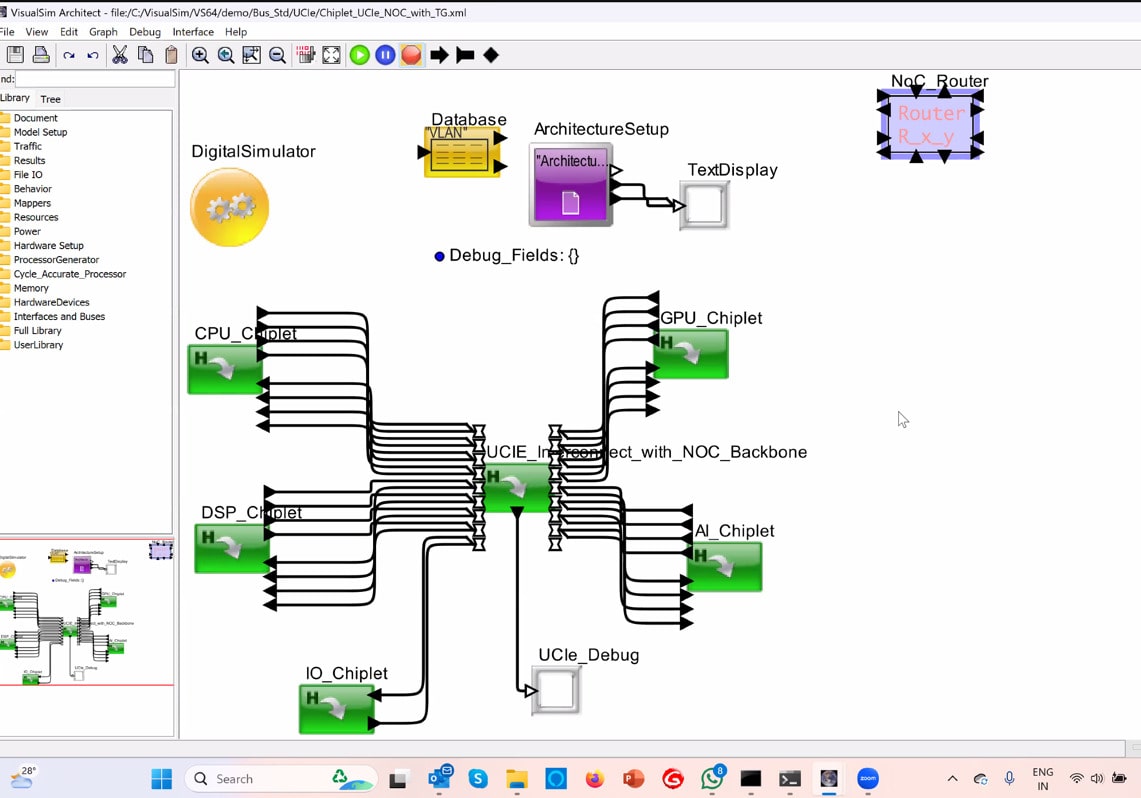
For the live demo Deepak showed me a chiplet-based design that had separate chiplets for the DSP, GPU, AI processor and CPU all connected together using UCIe, and each IP block was parameterized to allow for customization and exploration.
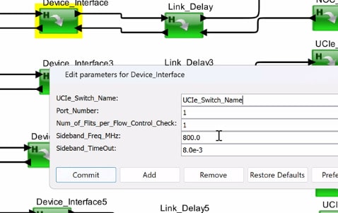
Pushing into the UCIe block there was an IP called a UCIe switch, and a user can customize this block with five parameters, all at a high level.
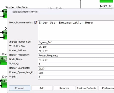
A router IP block had 10 parameters for customization.
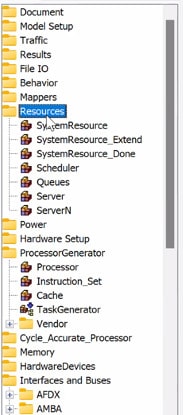
To find each IP block there was a scrollable list on the left-hand side of the GUI, with each family of IP in the library. In a matter of seconds you can browse, select and start customizing an IP.
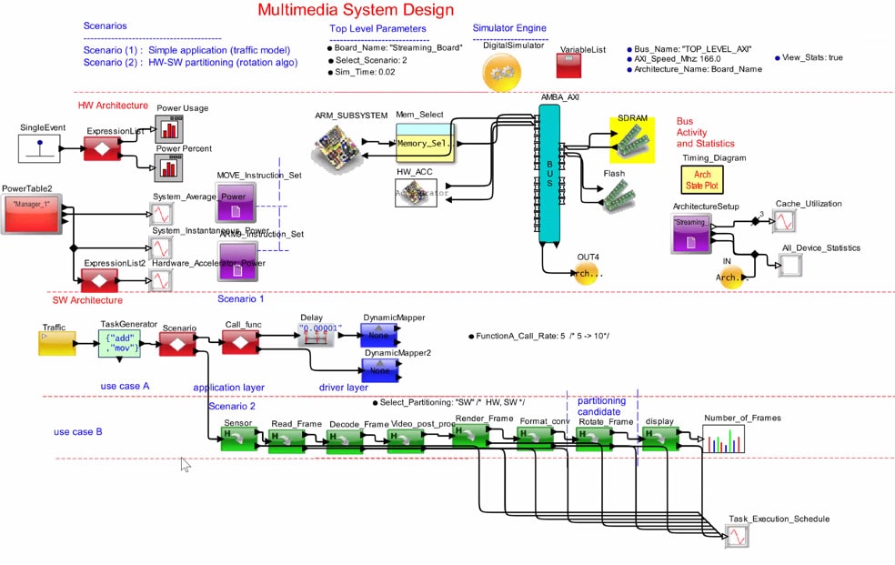
In VisualSim you are connecting each IP in the dataflow, staying at a high level. The next live demo was for a multimedia system design, and to simulate 20 ms took about 15 seconds of wall time, running on a laptop. While the simulation is running you can view the system performance as instantaneous power, measure pipeline utilization, cache utilization, memory usage, and even view a timing diagram. This real time simulation triggered 7.5 million events, and the customer built this model in under 2 weeks, which included the entire SoC.
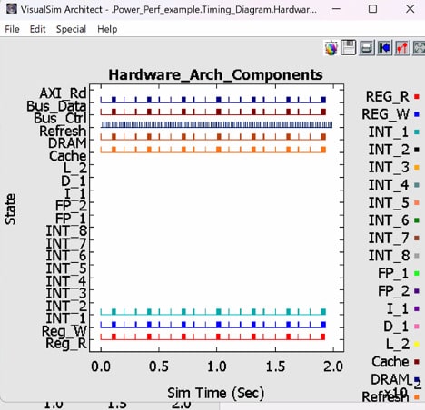
Another customer example that Deepak mentioned include 45 masters and was completed in about 4 weeks, fully tested.
You can look inside any of the IP blocks and analyze metrics like pass/fail, then understand why it failed. There’s even an AI engine to help analyze data more efficiently, like finding a buffer overflow which caused a failure. While your model is running there are analytics captured to help measure system performance and identify architectural bottlenecks.
VisualSim is updated twice per year, and then there are patch updates for when new IP blocks are added. An architect defines requirements in an Excel file, with metrics like latency limits and buffer occupancy.

Users of VisualSim can define the range of payload size in terms of bytes, speed ranges and preferred values. Your system model can be swept across the combinations to find the best set of parameters. The simulator even understands how to explore the min, max, and preferred values. You get to define which system parameters will be explored. A multimedia system demo was shown next and then simulated live.
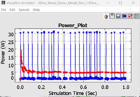
For an FPGA block you choose the vendor and part number, and then you can see the latency for each Task and the channel statistics of the NOC after a simulation has been run. A power plot was shown for 1 second of operation when using Xilinx Versal parts.
All of the live demos were being run on a Windows laptop. Other supported OSes are: Unix, Mac. Running VisualSim requires a minimal HW infrastructure, because the models are high level.
VisualSim users receive over 500 examples that are pre-built to help get you started quickly, like a complete communication system with an Antenna, Transceiver, FPGA with baseband, and Ethernet interface. System architects using VisualSim can collaborate with all the low-level specialists, like RTL designers.
System-level trade-offs can be modeled and evaluated, like:
- Changing from 64-QAM to QPSK modulation
- Faster to slower processor
- Changing Ethernet specs
If you start with VisualSim to model, implement, then measure, expect to see 95% accuracy compared to RTL implementation results. The promise of using high level models is to eliminate performance issues prior to implementation or integration. There really is no coding required for an entire system model.
Mirabilis has 65 customers worldwide so far and some 250 projects completed. Some of the well-known clients include: NASA, Samsung, Qualcomm, Broadcom, GM, Boeing, HP, Imagination, Raytheon, AMD, Northrup Grumman.
Summary
In the old days a systems designer may have drawn out their ideas on a napkin while eating at a restaurant, and then go back to work and cobble together some Excel spreadsheets with arcane equations to create a model. Today there’s a new choice, and that’s giving VisualSim from Mirabilis a try. You can now model an entire system in a just a few weeks, along with making architectural trade-offs while running actual simulations, all before getting into detailed implementation details.
Related Blogs
- Chiplets Open Pandora’s Box
- WEBINAR: How to Achieve 95%+ Accurate Power Measurement During Architecture Exploration
- Mirabilis Invites System Architects at DAC 2023 in San Francisco
- Mapping SysML to Hardware Architecture
- Model-Based Design Courses for Students
- Rethinking the System Design Process


Comments
There are no comments yet.
You must register or log in to view/post comments.