RVN! 26 Banner revised (800 x 100 px) (600 x 100 px)

SoC Integration – Predictable, Repeatable, Scalable

SoC Integration – Predictable, Repeatable, Scalable
by Bernard Murphy on 03-24-2021 at 6:00 am

IPDD SIPD stack min

On its face System-on-chip (SoC) integration doesn’t seem so hard. You gather and configure all the intellectual properties (IPs) you’re going to need, then stitch them together. Something you could delegate to new college hires, maybe? But it isn’t that simple. What makes SoC integration challenging is that there are so many parts including IPs and connections. . Some are moving parts, changing as bugs are fixed. Some, like the interconnect, can only be completely defined when you integrate.

There’s a lot of interdependence between these parts. Make a small change like importing a new revision of an IP or adapting to a spec tweak, and the consequences can ripple through your integration. Not a big deal, perhaps, early in design. But a very big deal when you’ve finally wrestled hundreds of IPs and tens of thousands of connections into behaving. Then you have to drop in a couple more changes. Surely there’s a better way?

Merging Design Data Integration and NoC Integration

It is now possible to script much of design data assembly, configuring IP models and stitching them into a top-level netlist. Experts define interconnect as an independent step, to manage connectivity expectations with quality-of -service (QoS) goals. Altogether a surprisingly manual, highly human-dependent approach to assembling the crown jewel at the heart of a critical product plan. Experienced engineers and a proven base of scripts make it work but can look quite fragile when creating a new product family or when key team members leave.

A better way is to merge a proven, robust strategy for design data integration through IP-XACT with a proven approach for interconnect generation through network-on-chip (NoC) technology.

Design Data Configuration Through IP-XACT

IP-XACT usage is now well-established and very active. Teams get a consistent representation of an IP today in the IP-XACT model, whether from Arm, Synopsys, Cadence or any other supplier. Some designers still see these models as a passive store for bits of information they need (like register data). But they’re on the trailing edge of a growing trend to using these models directly in IP-XACT-based integration. Initially starting in automotive and consumer semiconductor shops, IP-XACT assembly is now spreading to the big systems houses, communications giants, medical instrumentation experts and more. They still have the flexibility to hand tweak where needed, but only where needed. Our one-time artisanal pride in hand-assembling or scripting top-level netlists is losing out to the urgency of system-level needs.

Naturally, this simplifies the connection to NoC generation. When each IP-XACT model is already configured with interconnect interfaces, NoC generation can pick those up seamlessly. Designers optimize for QoS, power, floorplan and other key performance indicators (KPIs), confident that the IP interfaces are correct. If a new IP drop comes in, the NoC can be reconfigured for those interface changes with fewer opportunities for human error.

Software Interface Generation

Each IP-XACT model comes with detailed register map information: zero-based register offsets, bitfield widths, descriptions, access types, etc. The interconnect designer defines memory map offsets for each IP connection when building the NoC. Together this combination achieves the complete (hardware) memory map. Software creates or runs checks to ensure there are no overlaps and that each bit can indeed be read or written along with other options as defined. You can run those checks in simulation or formal verification.

Integrators can automatically generate a complete set of software header files using symbolic names for each register, bitfield, access macro and possibly sequence macros. Files automatically update each time the underlying design changes, whether through an IP or a NoC update. The software team can continue their development and debug, confident that the header files will be accurate against the latest design update. Once more – fewer opportunities for human error.

Documentation and Traceability

There is an enterprise component to product build that does not get much press in design flows. In the good old days, tech pubs would start with a largely frozen spec from which they would build product documentation for in-house or customer needs. A few engineering reviews, and they could sign off the doc. Now that specs and implementation decisions are evolving in larger designs on more rapid cycles, mistakes are more likely. Reviews are still essential for free-form text, but you can derive tables like clock, reset, memory maps from the design. Which become fair game for automating into the documentation, simply to ensure they are always in sync with the design. XML standards make the connection to the design definition much simpler.

Another enterprise need is to generate traceability documentation, essential for any safety-critical design. This is necessary in in automotive, aerospace and defense, industrial or medical domains. Traceability is another area that has historically required a lot of manual creation and checking. More automation could simplify these tasks, at least close to the design. This is an emerging area with exciting possibilities.

Talk to Arteris IP. They are building SoC integration solutions for current and future needs.

Also Read:

Arteris IP folds in Magillem. Perfect for SoC Integrators

The Reality of ISO 26262 Interpretation. Experience Matters

Cache Coherence Everywhere may be Easier Than you Think


Intel’s IDM 2.0

Intel’s IDM 2.0
by Scotten Jones on 03-24-2021 at 4:00 am

Slide1 1

In January I presented at the ISS conference a comparison of Intel’s, Samsung’s and TSMC’s leading edge offerings. You can read a write-up of my presentation here.

With the problems going on at Intel, that article generated a lot of interest in the investment community, and I have been holding a lot of calls with analysts who are trying to understand what is going on. Since I presented at ISS and have been participating in calls, I have continued to put effort into analyzing and understanding what is going on with Intel. This afternoon Pat Gelsinger announced Intel’s IDM 2.0 plan to bring the company back to technology leadership.

Before I get to today’s announcements I wanted to start with a little history and how intel got to where they are today.
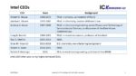
CEOs

From 1968 until 2005 Intel had four highly technical CEOs, in fact they are among the giants of our industry. The first CEO was Robert N. Noyce, a Ph.D. in physics and a co-inventor of the Integrated Circuit, Next up was Gordan Moore, a Ph.D. in chemistry and the man who coined Moore’s law, the law that has propelled our industry for decades. Moore was followed by Andrew S. Grove, a Ph.D. in chemical engineering. When I first started in the industry, Grove’s book “Physics and Technology of Semiconductor Devices” was the bible of devices and processing, Grove also discovered the Deal-Grove Oxidation law with Bruce Deal. Grove was followed by Craig R. Barrett, a Ph.D. in materials science and professor at Stamford University.

In 2005 Paul S. Otellini, an MBA became Intel’s first non-technical CEO. It was at the end of Otellini’s tenure that Intel began to slip from their process introduction cadence. Otellini was followed by Brian M. Krzanich who has a B.S. in chemistry and a manufacturing background, but, as Stacy Rasgon observed in a recent Podcast, for some reason he never really seemed to get his arms around Intel’s manufacturing issues with substantial yield problems with Intel’s 10nm process on his watch. The podcast is available here.

In 2018 Robert H. Swan, another MBA became CEO and held that position until recently.

I believe a company like Intel that is a historical technology innovator, needs to be led by a technical visionary. Recently Patrick P. Gelsinger has taken over as CEO, he has an M.S. in electrical engineering, was the lead architect for the 80486 and is a well regraded technologist in the industry. Only time will tell but he seems like a good choice to lead a technical turn around.

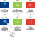
Figure 1 presents Intel’s CEO history.

Figure 1. Intel CEOs.

 Nodes

Figure 2 presents Intel’s nodes versus time and puts into perspective just how dramatic Intel’s delays have been.

In the first column of the table are the node names and in the second column is Intel’s actual introduction dates through 22nm, and then expected dates for subsequent nodes if Intel had kept on the same cadence. From 2001 when Intel introduced 130nm there was a steady two-year cadence of new processes and innovations (the two-year cadence goes back even before 130nm, but I truncated the sequence to make it easier to present). 90nm in 2003 saw the introduction of embedded silicon-germanium for strain, an industry first, 2005 saw the industry’s first use of high-k metal gate (HKMG), something the foundries did not introduce until 28nm in 2011. In 2007 Intel introduced 32nm and finally in 2011, 22nm with the industries first FinFET, something the foundries did not introduce until 2014. Clearly Intel was executing industry leading technologies on a regular cadence.

The third column of the table presents “reset 1” where 14nm was a year delayed to 2014, 10nm was expected in 2017 on a three-year cadence and eventually as 10nm was further delayed 7nm was expected in 2021. The next column has reset 2 where 10nm enters volume production in 2019 and then 7nm is delayed until 2022 originally blamed on COVID. The next column has reset 3 where 7nm production is now expected in 2023, this is an amazing delay for a process that would have been expected in 2017 back when Intel was executing to a two-year cadence. The next column presents “reset 4” based on what could happen if Intel got back on a two-year cadence.

The last two columns present the interval between each process in years and comments on the processes.

Figure 2. Intel Nodes Versus Time.

 Hyper Scaling

Intel’s success in introducing industry leading technology in advance of the foundries led to hyper scaling, an acceleration of scaling per node. Historically a typical node delivered 2x the density but now Intel targeted 2.5x for 14nm and 2.7x for 10nm. I believe this played a role in Intel’s slips. If you think about coming up to bat in Baseball, you strike out a lot more when you are trying to hit home runs then when you are trying for singles. Hyper scaling was introduced while the industry was seeing a dramatic increase in process complexity due to multi-patterning.

Figure 3. illustrates Intel’s hyper scaling.

Figure 3. Hyper Scaling.

 While Intel has been slipping on process introductions, Samsung and TSMC have been introducing new nodes at a faster rate. The foundries generally take smaller jumps in density but do it more frequently. I believe this reduces risks and increases the rate of learning.

Figure 4. illustrates the foundries introduced five full nodes between 2014 and 2023 while Intel introduced 3 nodes.

Figure 4. Node Introductions.

There are some subtleties this figure does not address, for example Intel has 14, 14+, 14++, 14+++ and 14++++ variants and for 10nm has 10 and now 10SF. However, these plus processes are performance enhancement and do not improve density meaning they are missing out on density improvement learning. The foundries also have “half-nodes not shown here, for example Samsung has 11nm, 8nm, 6nm and 4nm process nodes, and TSMC has 12nm, 7nm plus, 6nm, 5nm plus and 4nm and most of these do provide density improvements.

Culture and brain drain

With Intel’s several year lead on key technologies such as HKMG and FinFETs, Intel had an incentive to not share technical information. Intel was known in the industry to buy tools, bring them in house and not share what they were doing with the Original Equipment Manufacturers (OEM). This helped to protect Intel’s technology but may have also cut them off from taking advantage of the OEM’s increasingly sophisticated in-house process development capabilities. When I first started in the industry, we bought process tools, brought them in house and developed a process to run on them. Today the OEMs provide integrated sets of tools and processes that provide complete process modules.

Internally I have heard that very few people at Intel have a holistic view of a process, that generally engineers only know their tool, if true this would make it difficult to troubleshoot complex interactions between tools.

It is reported that there has also been an exodus of talent from Intel where many of the more experienced engineers have left. I know people who used to work at Intel and told me they had no intension of leaving or retiring but they were offered such generous financial packages that it did not make sense not to leave.

Intel is only as good as their people.

Double edged swords

Intel has two practices that I will refer to as double edged swords because while they provide benefits they also cause problems.

The first one is “copy exact”. At Intel when a process is developed at one of the development fabs, the entire tool set is frozen and when the process is transferred to a production fab an exact replica of the development tool set is installed and set up the same way. This ensures that the process put into manufacturing exactly copies the process that was developed. This helps with initial yield but the downside to copy exact is that as time passes the OEMs are introducing improved tools and even after several years have passed new lines are being set up with tools that are several years old. If you consider Intel was adding 14nm capacity in 2020 and the process was developed around the 2012 timeframe, you can see where this could be a significant issue.

The second issue is nonstandard design flows. Now I am not an expert on design flows, but my understanding is foundries have design flows based on PDKs, with standard cells and relatively simple design rules. I have heard that Intel does a lot of custom tuning of cells. The custom tuning may help squeeze the last little bit of performance out of a design, but it also makes it harder to deal with process changes or port design to a whole new process. Because foundry customers often try to second source parts with more than one foundry, they must be efficient at adapting to different processes. I cannot help but wonder whether this plays a role in Intel’s +, ++, etc. process not including shrinks and also in Intel’s 10nm yield issues.

10nm

Intel’s 10nm process has suffered from well documented delays and yield ramp issues. Intel’s 10nm process was originally targeted to utilize EUV but then due to delays in the development of EUV Intel had to resort to optical multipatterning. It appears that the transition in this process to optical multipatterning did not go smoothly.

For example, at 10nm Metal 0 (M0) and Metal 1 (M1) are patterned with Self Aligned Quadruple Pattering (SAQP) with 2 and 3 cut masks. This is the only use of SAQP in interconnect layers that I am aware of in the industry. Intel’s 10nm M0 and M1 also have the industries only use of cobalt interconnects and aluminum oxide tip to tip spacers I am aware of. The net result is a more complex fabrication scheme for these layers than I believe anyone else in the industry uses. SEM shots I have seen of 10SF M0 and M1 patterns still do not look good compared to foundry 7nm M0 and M1 patterns.

There was a rumor at one point that Intel was going to adopt EUV for a couple of layers for 10SF to address yield issues but that did not materialize, I can’t help but wonder how much the difficulty of porting designs to EUV with the non-standard design flows discussed in the previous section played into that decision.

Node Name Disconnect

There was time when node names for logic processes were the gate length tying them to a specific measurable feature. That is no longer the case and node names today are largely the creation of the marketing departments with no correlation to measurable features. There is a large disconnect between Intel’s node names and the foundry node names. For example, I have taken TSMC’s node names and plotted them versus TSMC’s actual measured transistor density. I have fit a curve to that data and gotten a good curve fit with an R2 value of 0.99, see figure 5.

Figure 5. TSMC Node Names Versus Transistor Density.

Using the formula for the line in figure 5. and actual measured Intel transistor density we can determine equivalent node names for Intel’s processes using TSMC’s trend. The net result is Intel’s 10nm process has a TSMC equivalent node of 7.4nm and Intel’s forthcoming 7nm process is projected to have a TSMC equivalent node of 4.3nm (based on an announced 2x density improvement). Figure 6. presents a comparison of TSMC and Intel processes with TSMC equivalent nodes for Intel processes out to a projected 3nm process. Please note that the values in this table are updated relative to a previous article.

Figure 6. Node Name Disconnect.

 From the figure we can see that Intel’s 7nm process falls between TSMC’s 5nm and 3nm process in density. I would like to encourage Intel to consider changing their 7nm process node name to 4nm to more accurately reflect how it compares to TSMC’s industry leading process and address a lot of confusion among analysts on how the processes really compare.

The other interesting observation is if Intel can get back to a two-year node cadence with 2x density improvements around mid-decade they can be roughly at density parity with TSMC although generally about a year behind.

I do want to note that density is not everything, particularly for Intel’s microprocessors where performance is king. As best as I can estimated Intel’s 10SF process and TSMC 7nm process have similar performance, certainly AMD is producing microprocessors on TSMC’s 7nm process that are competitive with Intel’s microprocessors. My expectation is that Intel’s 7nm process will be competitive with TSMC’s 3nm process on a performance basis but with TSMC 3nm entering risk starts later this year and production next year, Intel needs their 7nm process to be complete by the end of next year and ready for high volume production in 2023 or AMD could gain a process advantage by utilizing TSMC 3nm.

In terms of Intel’s catching or passing TSMC, as Stacy Rasgon observed in the PodCast I mentioned earlier, TSMC would have to stumble. I have had several people ask me why Intel does not just accelerate 5nm development. As we will discuss shortly Intel has already struggled with 7nm, a process where the main innovation is EUV that is already in second generation production at Samsung and TSMC. At 5nm I expect Intel to adopt Horizontal Nano Sheets (HNS) a process I believe still has unsolved engineering challenges. Samsung is trying to begin risk starts on their 3nm GAA process using HNS later this year and I am hearing that process is delayed.

IDM 2.0

This brings us to todays presentation on Intel’s IDM 2.0 announcement.

Intel’s key goals are:

  1. Lead in every product category they participate in.
  2. Innovate with boldness.
  3. Execute flawlessly.
  4. Foster vibrant culture.

As general goals these are great. There appears to be a recognition of the kinds of cultural issues we discussed earlier, and execution definitely needs to improve. A favorite comment of mine from tonight was bringing back a “Groveian culture of execution” in reference to former CEO Andy Grove who was well know for relentlessly driving execution.

The central tenants of IDM 2.0 for Intel are:

  1. Utilize the Intel internal factory network to build the majority of Intel’s products internally.
  2. Expand use of foundries so that all products have some level of foundry production.
  3. Increasing engagement with TSMC, Samsung, GLOBALFOUNDRIES (GF) and UMC.
  4. Plan to be a major foundry with US and European based manufacturing to balance the reliance on Asia.

There was slide that showed something like 80% of leading edge in Asia centered around Taiwan and South Korea, 15% in the US and 5% in Europe.

The idea of making the majority of product internally while also expanding foundry use is somewhat at odds to each other. It seems like foundry is being used to hedge Intel’s bet on getting 7nm out on time. Also, how do you engage more with foundries while starting a foundry business to compete with them.

There was discussion that Intel is making big investments in industry standard PDKs and simplified design rules. This addresses the earlier comments on Intel’s nonstandard design practices and is both a key enabler for servicing foundry customers and making it easier for Intel to port their own designs to foundries.

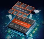
There was a lot of emphasis on Intel’s packaging technology with EMIB and Foveros enabling tiles as opposed to chiplets where the quality of the chip-to-chip interconnect is more like long wires on a chip.

Intel is going to partner with IBM on technology, I am not sure I see this as a plus. Samsung and IBM developed the 5nm process Samsung is running and it isn’t competitive with TSMC. They also worked together on the HNS technology in Samsung’s 3nm process and that is even less competitive with TSMC.

Misjudging EUV

I found the comments on the issues with 7nm very interesting. 7nm was developed to limit EUV usage due to “immaturity”. Now that EUV is more mature they have rearchitected and simplified the process using 100% more EUV layers.

What I find particularly interesting is the problems at 10nm can be traced to expecting EUV to be ready before it was and having to redo the process and then at 7nm to underestimating EUV readiness and having to redo the process. This is suggestive of a fundamental problem in Intel’s ability to understand the readiness of a process and appropriately plan for it. This is particularly glaring considering TSMC executing flawlessly on implementing EUV on their 7+ process and 5nm process. Samsung also did a good job of timing EUV with their decision to only have a 7nm process that uses EUV for critical layers (TSMC did an optical 7nm and then EUV 7+ process).

Another area around Intel’s EUV implementation that continues to concern me is availability of tools. I have heard that Intel has pushed out or canceled EUV tool orders during the 7nm delay. If they are pushing out tool to get NXE:3600D tools in place of NXE:3400C tools that makes sense but if they are giving up EUV slots they may not be able to get the EUV tools they need when they need them. TSMC is buying tools to continue to the 5nm ramp, equip for 3nm and for 2nm development, Samsung is doing the same plus has started using EUV for DRAM. SK Hynix recently committed to over $4 billion dollars of EUV tools for DRAM.

Intel has roughly 170k wafer per month (wpm) of 14nm capacity and is ramping 10nm with around 130k wpm of current capacity. If they built out something like 140k wpm of 7nm they could need around 45 EUV tools. They also announced plans for two foundry fabs that could need another 30 EUV tools. Where are they all these EUV tools going to come from?

Foundry pluses and minuses

Part of today’s announcement was that Intel is going to get into the foundry business with a dedicated foundry business with its own P&L and reporting directly to the CEO. Further they plan to build two dedicated foundry fabs in Arizona for approximately $20 billion dollars. I estimate this investment is sufficient for 2 – 40k wpm fabs running 7nm. CORRECTION, these fabs are not dedicated to foundry, they will produce Intel’s own products and also support foundry.

This begs the question of why Intel is doing this and what are the pluses and minuses. The funny part about this is some people have been suggesting Intel should go Fabless and citing AMD going fabless as an example.

Some thoughts on this:

  1. Pat Gelsinger mentioned that they think foundry is a good business and want to be in it. The interesting thing about foundry is it an excellent business for TSMC but not as good for other leading-edge competitors who have much lower margins. TSMC’s margins for Q4-2020 were around 54%, their next biggest competitor who publicly discloses their results is UMC and their margins for Q4-2020 were only around 24%, SMIC and GF have had many years with negative gross margins.
  2. Intel was in the foundry business before and failed. Pat admitted they had not been serious about it before. My observation when they were in the foundry business was, they would introduce a new process for their microprocessors and then a year or more would pass before the foundry version was available. To send the message that you are serious in the foundry space, the processes would have to come out at the same time. Pat talked about making the full portfolio of Intel technology available to foundry customers including process technology, IP and packaging technologies. Intel will offer their own cores and support Arm cores.
  3. Intel plans to build two fabs in Arizona for foundry and then possibly dedicated capacity in Europe in the future, certainly dedicated capacity helps to send the message they are serious and will commit to meet customer needs.
  4. There is a lot of push right now in the US and Europe for onshore leading edge manufacturing and the promise of subsidy money. Intel could potentially get government money and they are going after department of defense opportunities.
  5. If you look at TSMC they build a fab for a particular technology and in many cases the fab stays on the technology forever. TSMC is still running 130nm, 90nm, 65nm, 40nm, etc. on 300mm wafers. Somewhat counter intuitively new processes have lower margin because the equipment is depreciating. TSMC often talks about a new process pulling down corporate margins by about two percentage points for the first two years it is in production. Once a fab equipment set is fully depreciated, the wafer manufacturing cost is cut by more than one half but the foundries don’t pass all of the saving on to the customers. The net result is the older fabs generate the highest margins. At Intel all the fabs making processes larger than 32nm have been converted to smaller nodes.
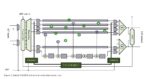
  6. A key consideration in all this is manufacturing scale. With scale you get more learning, and you can amortize the cost of developing a process over more wafers. This is what doomed GF 7nm, they were only going to build out 15k wpm of 7nm and that was not enough scale to stay competitive. By being in the foundry business Intel can build and maintain more scale. If they do not get in the foundry business, outsourcing to foundries and any market share losses to AMD reduce Intel’s scale potentially starting a death spiral. I was asked on a call whether Intel ran enough wafers to compete with TSMC, TSMC has roughly twice the total 300mm capacity of Intel but Intel’s capacity is concentrated more toward the leading edge meaning they run similar numbers of leading edge wafers, see figure 7.

Figure 7. Critical Mass.

  1. My big concern in all this is that it will take years to build up this business and engineering talent will have to be diverted to designing, building equipping and starting up the new fabs. Foundry specific versions of processes will have to be developed and PDKs built. This risks taking focus off of what is in my view Intel’s single biggest need right now, and that is to get 7nm out with good yield. Intel is also still struggling to make enough 10nm wafers.

Go Fabless

There has been a lot of talk about why Intel does not just go fabless like AMD did. There are several reasons why this is not a comparable situation:

  1. AMD went fabless because they had too, they simply could not afford to maintain a competitive fab capability.
  2. AMD was able to spin out their Fabs with backing from oil money. At the time AMD only had two – 300mm fabs with a combined capacity of around 45k wpm. Intel has roughly 15 logic fabs with around 450k wpm of capacity. Who is going to buy and be able to support that scale of manufacturing? Also keep in mind that GF lost money for a many years, who would be willing to support large losses from the Intel fabs.
  3. If Intel were to try to transfer all their business to a foundry even TSMC would need many years to build up the capacity. I suppose you could ask TSMC to take over Intel fabs but they would likely want to do a lot of retooling.
  4. If Intel were to go to TSMC, TSMC’s wafer prices are higher than Intel’s cost and it would drag down Intel’s margins. Intel’s internal manufacturing cost is higher than TSMC’s internal manufacturing cost, but TSMC adds an average gross margin of 54% to their wafers for sale. Although with Intel’s volumes they would pay a significantly lower margin, the margin would still yield wafer prices higher than Intel’s cost. Intel noted this on a previous call discussing this issue.
  5. In my opinion the best option for Intel is to get 7nm out the door, get back on track and make their products internally. They should hedge their bets at foundries to some extent but if they outsource too much, they lose scale.

To-Do List

I was writing a “What’s Wrong with Intel and How to Fix It” article before today’s call and I had been building my Intel to-do list. Here is my list with where things are after today:

  1. Hire a technical visionary CEO – Pat Gelsinger must show he can get the job done but he is certainly well regarded.
  2. Address the culture issues and brain drain – this seems to be recognized as a problem and getting attention. Some key players have returned.
  3. Adopt industry standard design practices – this was discussed today and is underway.
  4. Abandon “Copy Exact”, equip fabs with the best tools available at the time and take full advantage of OEMs process capabilities – I have not heard of any discussion on this.
  5. Go to more frequent new nodes with smaller jumps to accelerate learning and reduce risk – there was discussion today about fixing the development process and getting to a yearly cadence.
  6. Update node names – align nodes names with what the foundries are doing – I think this would help reduce confusion, but I do not know if it is being considered.
  7. Get 7nm into production by the end of 2022 and high volume in 2023 – I think this should be Intel’s number one priority.
  8. This one was not on my list until today, but I think Intel must be careful not to let building a foundry business dilute focus and interfere with execution. This is a lot to take on and frankly I am not convinced this is the right move at this time. Certainly, this could be good for the US, for the electronics industry starved for chips and for the defense department but Intel has to get back on track on process development.

Podcast EP12: A Close Look at Intel with Stacy Rasgon


Intel Will Again Compete With TSMC

Intel Will Again Compete With TSMC
by Daniel Nenni on 03-23-2021 at 2:00 pm

TSMC Intel SemiWiki

New Intel CEO Pat Gelsinger is not wasting any time in changing the course of the largest semiconductor company the world has ever seen. Today he announced the IDM 2.0 strategy which will better leverage Intel’s manufacturing abilities. There is a lot to talk about here but let’s focus on the new Intel Foundry Services because the mainstream media will have no idea what this really means and I am one of the only people with a website who can explain it.

IDM 2.0 is the Powerful Combination of Intel’s Internal Factory Network, Third-party Capacity and New Intel Foundry Services

Intel has dabbled in the foundry business on multiple occasions throughout the years but the biggest push was Intel Custom Foundry in 2014 . Unfortunately, the Intel Custom Foundry strategy was very critical of the pure-play foundry business model which did not go over well with the fabless semiconductor ecosystem, not even close.

In fact, looking back, it reminds me of the famous sleeping giant quote: “I fear all we have done is to awaken a sleeping giant and fill him with a terrible resolve”. The sleeping giant is the fabless semiconductor ecosystem of course.

On a side note: TSMC already shared their thoughts on this with Mark Liu’s IEDM keynote: Unleashing the Future of Innovation which speaks to the downside of IDM foundries.

Per today’s press release:

“Building a world-class foundry business, Intel Foundry Services

  1. Building a world-class foundry business, Intel Foundry Services. Intel announced plans to become a major provider of U.S.– and Europe-based foundry capacity to serve the incredible global demand for semiconductor manufacturing. To deliver this vision, Intel is establishing a new standalone business unit, Intel Foundry Services (IFS), led by semiconductor industry veteran Dr. Randhir Thakur, who will report directly to Gelsinger. IFS will be differentiated from other foundry offerings with a combination of leading-edge process technology and packaging, committed capacity in the U.S. and Europe, and a world-class IP portfolio for customers, including x86 cores as well as ARM and RISC-V ecosystem IPs. Gelsinger noted that Intel’s foundry plans have already received strong enthusiasm and statements of support from across the industry.

I am one of the above mentioned supporters from across the industry. Competition is critical in the semiconductor industry as with any other industry that relies on innovation and pricing. Intel can easily replace Samsung as the #2 foundry based on the US and UK fab locations alone given the semiconductor supply chain issues we are seeing today.

But it’s not as easy as it sounds and there are many potential pitfalls. First and foremost is the support of the giant fabless semiconductor ecosystem. It will be interesting to see how Intel goes about this. Personally, I would go all-in-it-to-win-it and start writing some very big, very strategic checks. Acquisitions will be key here as well as partnerships.

Another pitfall is trust. This has been a serious problem for Samsung even after they “spun off” the foundry business. Capacity and delivery for customers has always been a sticking point for IDM foundries starting with the early days of the fabless business where IDMs auctioned off their excess fab space while they had it. When they didn’t have it the fabless customers were out of luck.

Another trust issue is competing with customers. Today’s systems companies are the fastest growing fabless customers (Apple et al) and who is one of the biggest systems companies in the world? Samsung. Which is why the majority of Samsung Foundry customers are chip only companies. Word to the wise for Intel Foundry Services do not compete with customers.

The other piece of advice I have for Intel Foundry Services is to speak softly and carry a big stick, which is the opposite of what Intel Custom Foundry did. This also goes to trust. The semiconductor industry is filled with highly intelligent people who do not suffer fools gladly. And speaking of that, Intel please change your process node names to better align with the ecosystem. Us highly intelligent semiconductor people really feel strongly about this, absolutely.

I’m over 600 words so let’s talk more in the comments section.

Podcast EP12: A Close Look at Intel with Stacy Rasgon


Observation Scan Solves ISO 26262 In-System Test Issues

Observation Scan Solves ISO 26262 In-System Test Issues
by Tom Simon on 03-23-2021 at 10:00 am

Observation scan for ISO 26262

Automotive electronic content has been growing at an accelerating pace, along with a shift from infotainment toward mission critical functions such as traction control, safety systems, engine control, autonomous driving, etc. The ISO 26262 automotive electronics safety standard evolved to help ensure that these systems operate safely. There are four safety levels, ASIL-A though ASIL-D that help determine what level of safety features need to be implemented in a system. ASIL-A applies to a system where failure would only be a nuisance, ASIL-D is applied for systems where failure could lead to death.

In ISO 26262 there are requirements for detecting faults in the running systems. The goal is to detect a fault and return the system to a safe state before a hazardous event would occur. In normal operation a fault can occur at any time and the system must be periodically checking for them. The time between when a fault occurs and when it is detected is called the Diagnostic Time Interval (DTI). After a fault is detected the time until it is corrected and the system is returned to a safe state is called the Fault Reaction Time Interval (FRTI). The sum of the DTI and FRTI must not exceed the Fault Tolerate Time Interval (FTTI), which is the time until a hazardous event would occur.

It is easy to tell that the Diagnostic Time Interval needs to be as short as possible, especially when the Fault Reaction Time is longer and/or the Fault Tolerant Time Interval is short. The technique of Logic Built in Self-Test (LBIST) is used to diagnose systems for failures during operation. The running system, or portions of it, are taken offline and LBIST is run in real-time to look for faults. It is essential that the tests run quickly and have high coverage to meet the ISO 26262 requirements.

Siemens EDA has written a white paper titled “Tessent LogicBIST with Observation Scan Technology” that discusses the considerations involved with running LBIST for In System Test (IST). ISO 26262’s ASIL-D safety level calls for 90% stuck-at fault detection. However, in many automotive systems only around 5 to 50 milliseconds is provided for running LBIST patterns. When using traditional scan chain methodologies, it can be difficult to reach the required coverage. Siemens EDA’s Tessent LogicBIST offers Observation Scan Technology, which adds observation points in the design that can be captured by dedicated observation scan chain scan flops. These observation scan flops can capture faults at every shift cycle.

Observation scan for ISO 26262

These observation scan-flops can be shared with multiple observation test points to save silicon area. The observation scan chains are continuously shifted into the compactor which drives MISR signature generation. The observation scan chains are also shared with traditional LBIST scan chains, delivering responses once the entire test pattern has been shifted-in.

The Siemens EDA white paper describes the options available for placing the observation test points and how the modified scan cells operate. The overall flow is very similar to the typical LBIST flow. The Tessent Shell is used to create RTL based test logic and allows for a single pass flow for the gate level logic insertion.

The white paper includes a section on measured results comparing LBIST with and without observation scan technology. They ran tests on 10 designs ranging in size from 1M to 14M gates, with 44K-900K scan cells, and 200 – 3,200 scan chains. They considered three scenarios, baseline test coverage with no test points, using traditional test points and finally with the addition of observation test points. Test coverage went up significantly when observation test points were added, increasing by 7% to 27% with their addition.

As impressive as the coverage results were, the reduction in pattern count is the real story here. To reach 90% test coverage using observation scan used anywhere from 3X to 16X fewer patterns across the designs they looked at. The average reduction was around 10X. At the same time the silicon overhead for test points was reduced from 2% to 0.5% of the chip.

Siemens EDA talks about some very compelling technology that should make meeting the design goals of ISO 26262 much easier. Without pattern count reductions performing in-system test to get 90% stuck-at fault coverage will be impractical or difficult. The white paper discusses the flow and the specifics of the methodology in more detail. The full white paper can be downloaded from the Siemens EDA website.

Also Read:

Siemens EDA wants to help you engineer a smarter future faster

Happy Birthday UVM! A Very Grown-Up 10-Year-Old

The Five Pillars for Profitable Next Generation Electronic Systems


The Electromagnetic Solution Buyer’s Guide

The Electromagnetic Solution Buyer’s Guide
by Jim DeLap on 03-23-2021 at 6:00 am

automotive radar antenna array module

So you’ve decided to buy a new car? First you need to research, compare, and test drive before you finally get to drive that shiny new car home. Engineering teams choosing their preferred electromagnetic analysis tool face similar challenges. Historically, electromagnetic problems and analysis tools were relegated to a few “gurus” within an organization, however, more recently, tools are becoming more automated and easily used by the entire electrical engineering design team.

When exploring options for electromagnetic solutions, one of the first criteria for comparison is to look at the latest model. You wouldn’t compare the features and capabilities of the latest SUV with that of a five- or ten-year-old model. The latest SUV has all the best safety features, performance, and efficiency features that are just not present in older models. The same is true for analysis tools. The latest versions of electromagnetic solvers use current numerical methods for matrix solutions, the latest in meshing technology, as well as the most efficient use of HPC resources. Along with the latest version, it helps to be using the best known methods for setting up a design. Just like you no longer change out the spark plugs every tune up like you used to do to your 1976 Plymouth Duster, conditions that used to be “rules of thumb” when you used the tool back in college evolve over time, and some best-known methods turn out to be counterintuitive, or even counter to your previous practices. Check out this article discussing some of the best methods for Ansys HFSS.

One of the main selection criteria for EM solvers is how fast you get your answer, so that includes model setup and definition, analysis setup, solve, and post-processing. For the solve piece of that decision, you should make sure you’re using the same set of compute resources to run all your solutions. Whether you use existing company “on-premise” compute hardware or you are accessing cloud resources, it’s best to make sure you are performing an apples-to-apples comparison. This is just like taking those competing SUVs for test drives on the same roads. You want to see how they’re going to perform whether running errands in the city or commuting to the office on the highway.

One last consideration when making comparisons between electromagnetic solvers, and cars, is their efficiency, or how well they utilize resources. There are times where you may be limited to certain hardware resources inside your company environment, but with cloud resources readily available, it’s important to understand how much faster you could design if those constraints were removed. For Ansys HFSS, it’s a simple matter of choosing Ansys Cloud for the job submission, and you are open to almost unlimited possibilities. An example of solving an automotive radar array module is shown in the images. By using the cloud resources, this model solved almost five times faster. To read about these possibilities using Ansys HFSS in the Ansys Cloud powered by Microsoft Azure, check out this Microsoft post.

Automotive Radar Antenna Array Module

Automotive Radar Antenna Array Simulation Performance

Just as you have to research, compare, and test drive that new car before you get to enjoy the benefits, so should you take your electromagnetic solver out for a test drive. When you use the latest version combined with the best-known methods for problem setup and solve, combined with the virtually unlimited power of HPC with the Ansys Cloud, you will find that HFSS shines brighter than others in the industry. To find out more about HFSS, please find more information here, or join the world’s largest engineering simulation event, Ansys Simulation World.

Also Read

Electromagnetic and Circuit RLCK Extraction and Simulation for Advanced Silicon, Interposers and Package Designs

Need Electromagnetic Simulations for ICs?

Webinar: Electrothermal Signoff for 2.5D and 3D IC Systems


Siemens EDA Wants to Help you Engineer a Smarter Future Faster

Siemens EDA Wants to Help you Engineer a Smarter Future Faster
by Daniel Nenni on 03-22-2021 at 10:00 am

Xcelerator Digitalization Generic Image

In case you missed it earlier this year, Mentor Graphics the oldest EDA brand officially changed its name to Siemens EDA and launched a new website under its parent Siemens Digital Industries Software.

Under Siemens Digital Industries Software, Siemens EDA adds IC, advanced IC packaging and PCB systems design, verification/validation and manufacturing tools to Siemens Digital Industries Software’s line of Product Lifecycle Management (PLM) tools – a mix of mechanical engineering design and simulation technologies and end-product and manufacturing/factory-automation software built to improve product design as well as the processes for how products are manufactured.

The merging of the EDA and PLM worlds under Siemens Digital Industries Software comes at a seemingly opportune time, where several megatrends in electronics are converging.

From an IC perspective, an increasing percentage of systems companies are beginning to develop their own complex ICs for their end systems, and they are increasingly adding various forms of artificial intelligence and wireless communications to these ICs. This gives the systems companies a competitive advantage and allows them to leverage the data generated by the use of their products to monetize the data as well as to improve the quality and reliability of their products.

From a PLM perspective, an increasing number of customers are either just now making the jump to digitalization or making their digitalization more robust. Digitalization in a factory application, for example, means ensuring factory equipment from disparate vendors are connected and work together seamlessly and that a factory’s output can be monitored to achieve new levels of efficiency and safety – thus profitability. Digitalization also means that these factories can then, in turn, connect more closely with their supply chain, if in fact the suppliers also have a robust digital infrastructure.

You can see where this is going if you think of the trends not only toward smart, connected everything/IoT and monetizing big data, but also autonomous vehicles, smart factories, smart infrastructure and smart cities. Systems companies and their suppliers, including semiconductor vendors, are starting to develop a system of systems mindset. The real end-system isn’t just the IC, or the packaged IC, or PCB, the embedded software, or the ECU or even the autonomous automobile. The system will eventually be all that connected to the smart communications infrastructure. And at all levels, safety and security will be imperative and need to be verified, validated and tested individually and running together.

That’s where Siemens Digital Industries Software purports to have a differentiated offering and a lead over its key rivals – those providing technical software to industry that compete in only one or two domains. Siemens Digital Industries Software provides technical software and services in the greater PLM, IC, PCB and Systems Software markets and it also has offerings in areas like IoT Platforms, Application Lifecycle management, embedded software and Low-code markets. The combined offering and related services are marketed as its “Xcelerator Portfolio.”

Expanding the EDA landscape

Viewed solely through the lens as a pure-play EDA vendor and three years after Siemens announced the acquisition of Mentor Graphics, Siemens EDA still remains the third largest player in the EDA market. Like its competitors in EDA, Siemens EDA continues by all public reports to increase its revenue year over year, despite not having an IP business, which remains a sizable percentage of both Synopsys’ and Cadence’s reported EDA revenue. Maintaining a growing revenue record is no small feat considering most acquired companies typically see their revenue fall after an acquisition.

Certainly one of the main reasons for this growth is that Siemens has continued to invest heavily in Siemens EDA’s EDA portfolio over the last three years, making six notable acquisitions – including AI-in-EDA pioneer Solido, advanced IC place and route tool vendor Avatar, and semiconductor lifecycle management company UltraSoC – while also reportedly increasing its investment in EDA R&D.

After Wally Rhines’ departure from the company, Siemens also wisely promoted Mentor’s key executives to grow its EDA business. After a storied career introducing and turning the Calibre physical verification suite into the top brand and revenue earner for Mentor, Joseph Sawicki is now in charge of the entire IC business at Siemens EDA. Meanwhile, AJ Incorvaia, a long-time and well respectied veteran of the PCB systems space, was tapped to grow the IC advanced packaging and PCB systems divisions of the Siemens EDA business. Both report to Tony Hemmelgarn, CEO of Siemens Digital Industries Software.

All three executives have been emphatic about Siemens’ commitment to the electronics design community while also pointing to the unique advantages of a portfolio that brings EDA, mechanical design and software worlds closer together in potentially interesting and ground breaking ways.

In particular on the IC EDA front, Joe Sawicki has been outlining Siemens EDA IC strategy and how it is addressing three classes of scaling challenges: Process Technology scaling, Design scaling and Systems scaling to help customers “engineer a smarter future faster”:

Enable process technology scaling – Despite the ever growing challenges of device physics presented with each new process technology node, Siemens EDA continues to work closely with customers and foundry partners to deliver signoff, DFM, lithography and test for each emerging process node. Siemens EDA, said Sawicki, is also committed to delivering 2.5D and 3D advanced packaging for those customers wanting to achieve “More than Moore” densities and is also pioneering synthesis and layout tools for companies pioneering next gen IO with silicon photonics.

Enable design scaling – As companies take a more holistic systems of systems view of their chip designs and especially as more integrate AI/ML into their SoCs, chip architects can develop algorithms in C of their AI/ML blocks and leverage high-level synthesis to determine the optimal HW/SW architecture for their smart SoCs and achieve power, performance and area goals. Alternatively, they can use 2.5D and 3D advanced packaging to achieve their system goals. Whichever route they go, they can leverage power analysis throughout the entire flow from C level design down to implementation, which will become increasingly noteworthy with last year’s acquisition of Avatar and its Aprisa place and route tool.

Enable systems scaling –  Siemens EDA has already begun to pioneer new ground in verification, validation and more so what is commonly known as the digital twin. In fact, a year and a half ago, Siemens announced its PAVE 360, which ties Siemens EDA’s Veloce emulation system with a slew of PLM technologies to essentially verify automotive IC designs and validate related software in virtual driving scenarios before committing the silicon and the rest of the system to manufacturing. Siemens EDA’s Tessent group also pioneered a silicon lifecycle management technology called MissionMode and last year acquired UltraSoC, which enable companies to insert specialized IP blocks into their ICs that monitor in real time on-chip faults, security, power and performance of their ICs over the lifetime of the devices to perform tasks ranging from operating warnings to preventative maintenance or to improve derivative designs and even manufacturing processes.

If you are interested in learning more, check out the new Siemens EDA website. The new site is organized by electrical engineering functional discipline plus EDA consulting services:

Also Read:

Happy Birthday UVM! A Very Grown-Up 10-Year-Old

The Five Pillars for Profitable Next Generation Electronic Systems

Probing UPF Dynamic Objects


Why In-Memory Computing Will Disrupt Your AI SoC Development

Why In-Memory Computing Will Disrupt Your AI SoC Development
by Ron Lowman on 03-22-2021 at 6:00 am

dwtb q121 in memory comp fig1.jpg.imgw .850.x 1

Artificial intelligence (AI) algorithms thirsting for higher performance per watt have driven the development of specific hardware design techniques, including in-memory computing, for system-on-chip (SoC) designs. In-memory computing has predominantly been publicly seen in semiconductor startups looking to disrupt the industry, but many industry leaders are also applying in-memory computing techniques under the hood.

Innovative designs using in-memory computing are intending to disrupt the landscape of AI SoCs. First let’s take a look at the status-quo that startups using in-memory computing intend to disrupt. AI hardware has taken a huge leap forward since 2015 when companies and VCs started investing heavily into new SoCs specifically for AI. Investment has only accelerated over the past 5 years, leading to many improvements in AI hardware design for industry leaders. Intel’s x86 processors have added new instructions and even a separate NPU engine. Nvidia has added specific Tensor Cores and forsaken GDDR to implement HBM technologies to increase memory bandwidth. Google has developed specific ASIC TPUs, or Tensor Processing Units, dedicated to AI algorithms (Figure 1). But even though these architectures continue to improve, investors are looking to startups to develop the next disruption in AI technology.

Figure 1: Intel, Nvidia and Google are introducing new hardware architectures to improve performance per watt for AI applications

Why are Disruptions for AI Compute so Interesting?

The three key reasons for heavy investment into AI hardware are: 1) the amount of data generated is growing exponentially and AI is the critical technology to address the complexity; 2) the costs of running AI algorithms in power and time are still too high with existing architectures, specifically at the edge; 3) the parallelization of AI compute engines is reaching die size limits, driving these systems to scale to multiple chips which is only practical in cloud or edge-cloud data centers. Together, these new challenges are driving designers to explore new, innovative hardware architectures. In-memory compute is looked upon as one of the most promising hardware innovations because it may provide multiple orders of magnitude in improvements.

Paths for AI Compute Disruption

Startups and leading semiconductor providers are looking at potential paths for AI compute acceleration.

  • New types of AI models: New neural networks are being introduced quite often. For example, Google’s huge research team dedicated to releasing models has produced EfficientNet. Advanced Brain Research has released the LMU, and Lightelligence has partnered with MIT to run Efficient Unitary Neural Network (EUNNs).
  • Integrated photonics is being explored by several startups as another method for disruption.
  • Compression, pruning and other techniques are being developed to enable specific AI functions to operate on small, efficient processors such as a DesignWare® ARC® EM Processor IP running under 100MHz.
  • Scaling compute systems by packaging multiple die, multiple boards, or multiple systems is already in full production from the industry leaders. This solution is used to solve the most complex, costly challenges with AI.
  • These methods to increase performance are all being pursued or already realized. In-memory computing designs can build on these methods to drive efficiencies with multiple times improvements in addition to the other developing technologies.

What is In-Memory Computing?

In-memory computing is the design of memories next to or within the processing elements of hardware. In-memory computing leverages register files, memories within processors, or turns arrays of SRAMs or new memory technologies into register files or compute engines themselves. For semiconductors, the essence of in-memory computing will likely drive significant improvements to AI costs, reducing compute time and power usage.

Software and Hardware for In-Memory Compute

In-memory computing includes both hardware and software elements, which can cause some confusion. From a software perspective, in-memory computing refers to processing analytics in local storage. Basically, the software takes full advantage of the memories closer to the compute. “Memories” is a bit vague from a hardware perspective and can refer to DRAMs, SRAMs, NAND Flash and other types of memories within the local system rather than sourcing data over a networked software infrastructure. Optimizing software to take advantage of more localized memories has vast opportunity for industry improvement and teams of engineers will need to continue focus on these innovations at a system level.  However, for hardware optimizations, in-memory compute offers bit level innovations that more closely mimic the human brain which is 1000s of times more efficient than today’s compute.

In-Memory Compute, Near-Memory Compute, and Analog Compute

In-memory computing hasn’t just arrived as a magic solution to AI algorithms—it has differing implementations and is evolving from a progression of innovations. The implementation of register files and caches has been around for decades and near-memory computing has been the natural progression of improvement and has seen implementations in new SoCs over the past several years. AI algorithms require millions, if not billions, of coefficients and multiply-accumulates (MACs). To efficiently perform all these MACs, customized local SRAMs for an array of MACs are now designed into SoCs for the sole purpose of performing AI model math, i.e., matrix/tensor math. Integrating dedicated specialized local SRAMs for an array of MACs to perform AI model math is the concept of near-memory compute. In near-memory compute, local SRAMs are optimized for the purpose of storing weights and activations needed for their designated MAC units.

The next natural progression to develop in-memory compute is analog computing. Analog computing enables additional parallelism and more closely mimics the efficiencies of a human brain. For analog systems, MACs and memories are parallelized, improving the system efficiency even further than near-memory compute alone. Traditional SRAMs can be the basis for in-memory analog computing implementations and Synopsys has delivered customizations for this very purpose.

Memory Technologies Address In-Memory Compute Challenges

New memory technologies are such as MRAM, ReRAM and others are promising as they provide higher density and non-volatility when compared to traditional SRAMs. Improvements over SRAMs can increase the utilization of the compute and memory on-chip. Utilization is one of the most critical design challenges for AI SoC designers (Figure 2). SoC designers need memory subsystems designed specifically for AI data movement and compute regardless of the technology used.

Figure 2: AI SoCs have extremely intensive computation and data movement, which can impact latency, area, and performance

The key challenges for AI SoC design with memory systems relate back to the number of MACs and coefficients that need to be stored. For ResNet-50, over 23M weights are needed and that computes into 3.5 billion MACs and 105B memory accesses. Not all are running at the same time, so the size of the largest activation can be the critical bottleneck to the memory subsystems. Control engineers know that efficiencies are made by designing bottlenecks to be at the most expensive functions of execution. Thus, designs need to ensure that their in-memory compute architectures can handle the largest layer of activation coefficients effectively.

Meeting these requirements demands huge amounts of on-chip memory and intensive computation of the multiple layers. Unique techniques in memory design are being developed to remove latencies, remove the size of coefficients and remove the amount of data that must be moved around the SoC.

DesignWare IP Solutions for In-Memory Compute

Synopsys provides a wide array of IP options for customers to implement in-memory computing. Optimized memory compilers specific for density or leakage are used to develop the local SRAMs for near-memory implementations where sometimes 1000s of MACs are instantiated. MACs can leverage a portfolio of Synopsys Foundation Core primitive math functions that includes flexible functions such as Dot Product, a common AI function.

In addition, Synopsys DesignWare Multi-Port Memory IP enabling up to 8 inputs or 8 outputs improves parallelism within the compute architectures. Multi-port memories are much more common within designs since AI has become so prevalent.

Synopsys developed a patented circuit that demonstrates innovations supportive of in-memory compute. A Word All Zero function, shown in Figure 3, essentially eliminates zeros from being processed. Why move zeros to multiply? The Word All Zero function significantly reduces the compute required and can reduce power by up to 60% for data movement within the chip.

Figure 3: In addition to the Word All Zero function, Synopsys DesignWare Embedded Memory IP offers multiple features to address power, area, and latency challenges

Conclusion

How fast in-memory compute is adopted in the industry remains to be seen; however, the promise of the technology and conceptual implementation with new memories, innovative circuits and creative designers will surely be an exciting engineering accomplishment. The journey to the solution is sometimes as interesting as the final result.

For more information:

White paper: Neuromorphic Computing Drives the Landscape of Emerging Memories for Artificial Intelligence SoCs


Upcoming Webinar on Resistive RAM (ReRAM) Technology

Upcoming Webinar on Resistive RAM (ReRAM) Technology
by Kalar Rajendiran on 03-21-2021 at 10:00 am

eMemory RRAM Webinar Semiwiki

On-chip memory (embedded memory) makes computing applications run faster. In the early days of the semiconductor industry, the desire to utilize large amount of on-chip memory was limited by cost, manufacturing difficulties and technology mismatches between logic and memory circuit implementations. Since then, advancements in semiconductor manufacturing have been bringing on-chip memory costs down. In parallel, leading edge process nodes have been throwing new challenges to embedded memories. Of course, high-speed I/O interfaces have made it easier to use off-chip memories without sacrificing computing application speed. At the same time, new applications such as AI, machine learning, mobile and other low-power applications have been fueling demands for large amounts of embedded memories. Many of the existing embedded memory technologies face challenges as the process node goes below 28nm. The challenges are due to additional material layers and masks, supply voltages, speed, read & write granularity and area.

It is in this context that eMemory Technology Inc. will be hosting a webinar that will be very informative and useful for chip designers and semiconductor companies. The webinar is titled “eMemory’s Embedded ReRAM Solution on Nanometer Technologies” and is scheduled for March 24th, 2021. I got an opportunity to preview the webinar content. Following is just a few of the salient points that I’d like to share in this blog. Please register for the webinar to learn the full and intricate details.

The webinar will focus on a very promising technology called Resistive RAM (ReRAM) that will be available in production very soon. ReRAM is specifically designed to work in 40nm and finer geometry process nodes. In contrast, many of the other memory types such as Split-Gate Flash, Logic process MTP and Logic Process EEPROM face challenges below 28nm.

Due to ReRAM’s simplicity for process manufacturing, it can be integrated into Back End of Line (BEOL) with only a few extra masks and steps. ReRAM technology enables high-speed, low-power write operations and increased storage density, all critical for AI computing-in-memory application as an example.

Attendees will gain insights into ReRAM cell structure, switching methodology, and the suitability of ReRAM to various prospective applications. eMemory Technology will also share measurement results of their 40nm ULP and 22nm ULL ReRAM reliability data at 85C and 125C operation and 10-year retention data after 10K cycles.

Anyone who is looking into designing chip solutions in advanced process nodes for applications that could benefit from embedded memories would learn a lot from attending this webinar. Register here for the “eMemory’s Embedded ReRAM Solution on Nanometer Technologies” webinar.


RIP Jim Hogan – An Industry Icon

RIP Jim Hogan – An Industry Icon
by Bernard Murphy on 03-21-2021 at 8:00 am

RIP Jim Hogan

An unavoidable consequence of getting older is that more frequently our friends and colleagues unexpectedly leave us for their final venture. Jim Hogan, widely known and loved in the semiconductor industry, has passed on. He will leave a substantial hole in the hearts of many. Always ready with seasoned advice, a sympathetic ear and a boundless stock of entertaining stories. I for one will never forget his patient and encouraging support. For now, I must make do by remembering the man who helped and inspired me in so many ways. My thanks also to Peter Calverley and Scott Becker of Tela Innovations for filling in some of the blanks. RIP Jim Hogan, a dear friend to many of us.

The early days

I first met Jim in the late 80’s at National Semiconductor. He was a big wheel in computer integrated manufacturing, and I was a lowly CAD manger in the ASIC group. He left to join Cadence and I independently left for Cadence not long after. Our orbits didn’t overlap too much during that period, but I remember a friendly easy-going recognition at those times our paths did cross.

Jim stayed at Cadence for a while, running a division, later Japan Operations before moving on to Artisan Components as the head of Business Development. Which culminated in Artisan’s acquisition by ARM.  Jim then switched to what would become his true love – investing in and guiding early-stage ventures. If you were a Jim Hogan watcher at all, you’ll know he was involved with many successful exits. However, he was a modest guy. He told me that there were many more not-so-successful investments. He would often laugh about Theranos as one painful example.

Investing and guiding

Jim invested first through Cadence’s Telos Venture Partners. Later and together with Scott Becker, a close friend he first met at Artisan, he formed his own venture fund Vista Ventures.  At the same time Jim helped Scott form Tela Innovations and served on the board for over fifteen years.  Vista Ventures was the vehicle through which he invested in many of the companies we know he helped. Most recently Jim complemented his investment activity by joining the board of Silicon Catalyst.

Nothing could get Jim more excited than new technologies and new ideas. In my closing days at Atrenta, I got into blogging, particularly on harebrained ideas – which Jim enthusiastically encouraged. I’m not sure which of us was crazier. One blog was on how we could exploit biological security parallels (antibodies and so on) in system security. He wanted to turn it into a Ted talk. The guy was infectiously excited by any new tech idea.

He guided me in my early freelancing, helping setup assignments and introducing me to key executives looking for content marketing help or strategic marketing guidance. I was lucky to work together with Jim on some of these projects, for example the work we have done together with Paul Cunningham at Cadence in the “Innovation in Verification” series. Paul and I are the techie enthusiasts. Jim always grounded us with his investment insight. He also provided me with the content for chapter 4 of my recent book (The Tell-Tale Entrepreneur). That chapter offers a fascinating view into investment through the eyes of an investor.

The person

I wasn’t lucky enough to meet Jim’s family, but I know we shared common interests outside technology. We were always debating how to manage fire clearance, tractors and attachments, drilling new wells and building versus buying a new home. He talked often and affectionately about Lisa and even more often about Jake and his adventures, most recently his fascination with chain saws (I can relate).

My abiding impression of Jim is that for all his accomplishment and renown in the industry, he topped it by being one of the most genuinely nice human beings you could ever hope to meet and count as a friend. We all want to succeed in fame and fortune. Jim had those but more important he left a lasting impression as the kind of person we all hope to be when our time finally comes. Rest in peace Jim. We won’t find your like again.

If you would like to express your appreciation of Jim, please submit your entry to nominate him the the Phil Kaufman Hall of Fame.


Podcast EP3: Tomorrow’s Semiconductors with Jim Hogan


Micron- Optane runs out of Octane- Bye Bye Lehi- US chip effort takes a hit

Micron- Optane runs out of Octane- Bye Bye Lehi- US chip effort takes a hit
by Robert Maire on 03-21-2021 at 6:00 am

Intel Optane Micron SemiWiki

– Micron shuts down once promising XPoint
– Lehi Utah fab to be sold off- Had been a $400M drain
– Unique memory couldn’t follow flash down cost/yield curve
– Savings helps Micron but its now just another memory maker

XPoint “Coulda been a contender”

XPoint should have amounted to more than a footnote in semiconductor history. It promised speed between NAND and DRAM, closer to DRAM at costs approaching NAND with the benefit of being non-volatile.
But it wasn’t meant to be.

Intel pulled out of the partnership a while ago, not wanting to throw more money down a hole. It now looks like Micron was cleaning things up to get ready to shut it down.

We are certainly vey disappointed that in the end it didn’t work as it had clear promise and a shot at being the next memory technology since NAND was invented back in 1980.

Couldn’t get on the Moore’s Law cost/yield curve

The problems appears to be that the technology was never able to get on , let alone stay on, the Moore’s Law cost curve that keeps driving memory prices ever lower on a per bit basis.

You need two basic ingredients to make it work; yield and shrinks. The yield (percentage of working chips on a wafer) has to get to a point where there are enough working chips per wafer divided by the per wafer cost to make the needed market price to be competitive. Second the technology also has to work to the point where you can reliably shrink the dimensions of the chip design on a regular cadence to continually increase the number of bits per square inch to keep up with the market.

Was it the failure of XPOINT or the Success of NAND that caused XPoint’s demise?

Maybe it was both…..One could argue that moving NAND to a 3D architecture just accelerated it too far ahead from XPoint’s ability to ever keep up. Others could argue that XPoint never met its intended goals of price, performance and yield.

At this point a post mortem is almost pointless as its dead anyway.
However it does amplify exactly how incredibly difficult the semiconductor industry is, even with very deep pockets and both Intel and Micron supporting it, they still couldn’t get it to work well enough to make the cut.

Good and bad for Micron

The good news is that Micron will get rid of a $400M/year cash drain, the bad news is that Micron will be just another memory competitor up against the likes of Samsung and a more determined SK.

XPoint, had it worked , could have been a great differentiator that no other memory company had and would have put Micron in a unique position. Now they are relegated to slugging it out with Samsung and trying to find small niches where they have a unique advantage.

Don’t get me wrong….Micron has proven very good at weaving and dodging among the big boys and just outmaneuvered them by keeping a step or two ahead in certain areas. But XPoint could have been a different type of lifeline.

Not good for MRAM, RRAM & PRAM

There are a number of other memory technologies that are also being developed as competitors to todays DRAM NAND duopoly. All offer attractive alternative characteristics to DRAM or NAND. In our view, XPoint was likely the best funded memory alternative, had the best supporters, Intel & Micron and had both a dedicated fab as well as commercial installations in end customer products and it still failed.

Its going to be very difficult to do what XPoint couldn’t, even with all the attributes it had going for it.

Bye Bye Lehi- Its sale won’t help current shortage

Micron is selling off the associated fab in Lehi. The positive here is that they will likely get a reasonable price as compared to the scrap value that old fabs usually sell for given current demand.

It will cost a lot of time and money to re-configure the fab for logic as it is likely not big enough for anything other than specialty memory.

We would guess it could take a couple of years to re-configure so it isn’t going to be any help at all for todays current chip shortage.

We also wouldn’t be too sure that it will stay a fab at all. It may be more financially attractive for Micron to sell off the tools to be shipped off to Asia to be installed into fabs there as we have seen happen with other US fabs.

Maybe even Micron itself, which is the King of getting fabs on the cheap, might part out the bits and pieces of the fab to its own fabs where they could add incremental capacity.

Its not clear whether its worth more as parts or as a whole.

Doesn’t bode well for US chip efforts

This clearly flies directly in the face of current discussions about helping the US chip industry. Here we are with a US company, located in the heartland of Boise Idaho shutting down a US fab while continuing their overseas operations which have been expanding.

The US government, could put its money and effort where its mouth is and keep the fab in the US and in US hands. Perhaps it could be the first poster child and spearhead of the effort to boost the US semiconductor industry and save it from itself, or not. Wake up! this is an opportunity!

The stocks

Investors will clearly view this as a positive for Micron as it cuts the cash drain and may supply some short term cash before the end of the year. Longer term it makes Micron less competitive but investors don’t generally care about the longer term.

Its likely a neutral to slightly positive for equipment companies as Micron will have more money to spend but won’t be spending it on Lehi (not that there were any plans to spend anyway). Shutting down XPoint was somewhat expected so its not a huge surprise just more of a relief.

Micron’s stock is not that expensive as many investors do not believe forward earnings given the volatility of the memory industry. This may help them make numbers.

R.I.P. – XPoint/Optane & Lehi

Also Read:

Chip Channel Check- Semi Shortage Spreading- Beyond autos-Will impact earnings

Semiconductor Shortage – No Quick Fix – Years of neglect & financial hills to climb

“For Want of a Chip, the Auto Industry was Lost”