Automotive electronic content has been growing at an accelerating pace, along with a shift from infotainment toward mission critical functions such as traction control, safety systems, engine control, autonomous driving, etc. The ISO 26262 automotive electronics safety standard evolved to help ensure that these systems operate safely. There are four safety levels, ASIL-A though ASIL-D that help determine what level of safety features need to be implemented in a system. ASIL-A applies to a system where failure would only be a nuisance, ASIL-D is applied for systems where failure could lead to death.
In ISO 26262 there are requirements for detecting faults in the running systems. The goal is to detect a fault and return the system to a safe state before a hazardous event would occur. In normal operation a fault can occur at any time and the system must be periodically checking for them. The time between when a fault occurs and when it is detected is called the Diagnostic Time Interval (DTI). After a fault is detected the time until it is corrected and the system is returned to a safe state is called the Fault Reaction Time Interval (FRTI). The sum of the DTI and FRTI must not exceed the Fault Tolerate Time Interval (FTTI), which is the time until a hazardous event would occur.
It is easy to tell that the Diagnostic Time Interval needs to be as short as possible, especially when the Fault Reaction Time is longer and/or the Fault Tolerant Time Interval is short. The technique of Logic Built in Self-Test (LBIST) is used to diagnose systems for failures during operation. The running system, or portions of it, are taken offline and LBIST is run in real-time to look for faults. It is essential that the tests run quickly and have high coverage to meet the ISO 26262 requirements.
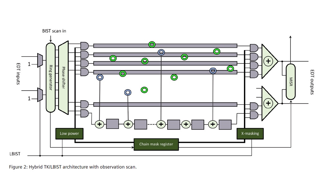
Siemens EDA has written a white paper titled “Tessent LogicBIST with Observation Scan Technology” that discusses the considerations involved with running LBIST for In System Test (IST). ISO 26262’s ASIL-D safety level calls for 90% stuck-at fault detection. However, in many automotive systems only around 5 to 50 milliseconds is provided for running LBIST patterns. When using traditional scan chain methodologies, it can be difficult to reach the required coverage. Siemens EDA’s Tessent LogicBIST offers Observation Scan Technology, which adds observation points in the design that can be captured by dedicated observation scan chain scan flops. These observation scan flops can capture faults at every shift cycle.

These observation scan-flops can be shared with multiple observation test points to save silicon area. The observation scan chains are continuously shifted into the compactor which drives MISR signature generation. The observation scan chains are also shared with traditional LBIST scan chains, delivering responses once the entire test pattern has been shifted-in.
The Siemens EDA white paper describes the options available for placing the observation test points and how the modified scan cells operate. The overall flow is very similar to the typical LBIST flow. The Tessent Shell is used to create RTL based test logic and allows for a single pass flow for the gate level logic insertion.
The white paper includes a section on measured results comparing LBIST with and without observation scan technology. They ran tests on 10 designs ranging in size from 1M to 14M gates, with 44K-900K scan cells, and 200 – 3,200 scan chains. They considered three scenarios, baseline test coverage with no test points, using traditional test points and finally with the addition of observation test points. Test coverage went up significantly when observation test points were added, increasing by 7% to 27% with their addition.
As impressive as the coverage results were, the reduction in pattern count is the real story here. To reach 90% test coverage using observation scan used anywhere from 3X to 16X fewer patterns across the designs they looked at. The average reduction was around 10X. At the same time the silicon overhead for test points was reduced from 2% to 0.5% of the chip.
Siemens EDA talks about some very compelling technology that should make meeting the design goals of ISO 26262 much easier. Without pattern count reductions performing in-system test to get 90% stuck-at fault coverage will be impractical or difficult. The white paper discusses the flow and the specifics of the methodology in more detail. The full white paper can be downloaded from the Siemens EDA website.
Also Read:
Siemens EDA wants to help you engineer a smarter future faster
Happy Birthday UVM! A Very Grown-Up 10-Year-Old
The Five Pillars for Profitable Next Generation Electronic Systems
Share this post via:


Comments
One Reply to “Observation Scan Solves ISO 26262 In-System Test Issues”
You must register or log in to view/post comments.