DAC2025 SemiWiki 800x100

Die-to-Die IP enabling the path to the future of Chiplets Ecosystem

Die-to-Die IP enabling the path to the future of Chiplets Ecosystem
by Kalar Rajendiran on 05-30-2022 at 6:00 am

Die to Die Interface Figure of Merit

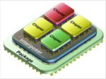
The topic of chiplets is getting a lot of attention these days. The chiplet movement has picked up more momentum since Moore’s law started slowing down as process technology approached 5nm. With the development cost of a monolithic SoC crossing the $500M and wafer yields of large die-based chips dropping steeply, the decision to pursue chiplets methodology is a no brainer. No wonder, companies such as AMD, Intel, Marvel and others who build leading-edge node, large die-size based chips were the early ones to successfully implement chiplets based products. While a chiplets implementation has its own challenges, these companies did not have to deal with the additional challenges of heterogeneous chiplets implementation.

For a broad-based adoption of heterogeneous chiplets implementations, there are several challenges to overcome within an open ecosystem. Packaging is one area but that has already seen lot of advances over the years with innovations including flip-chip, silicon interposer, 2.5D, 3D, chip scale packaging and wafer level packaging. Over the last few years, the area that is receiving lot of attention and investments is chiplets interfaces. Standards for communicating between chiplets are being promoted to standardize interfacing and ease heterogeneous chiplets implementations.

Recently, Intel, AMD, Meta, Arm, Google, Qualcomm, TSMC and ASE formed a consortium to promote an open standard called Universal Chiplet Interconnect Express (UCIe). UCIe 1.0 covers die-to-die physical layer, protocols and software stacks leveraging PCI Express (PCIe) and Compute Express Link (CXL) standards. The Open Domain-Specific Architecture (ODSA) Sub-Project is also working on standardization initiatives.

Letizia Giuliano, Vice President, Solution Engineering at Alphawave IP gave a talk at IP-SoC Silicon Valley 2022 last month. Her presentation focused on design challenges with chiplet integration and open ecosystem solutions. She compared the Die-to-Die (D2D) Interface Figure of Merit for various interface/package combinations and the open ecosystem that is driving chiplets adoption. She closed by presenting Alphawave IP’s configurable D2D PHY interface as a way to navigate the evolving landscape for interfaces for integrating chiplets. You can download her presentation slides from here. The following is a synthesis of the salient points from her presentation.

Design Challenges with Chiplet Integration

With a chiplet integration, a number of nanometer pitch wires that were on-chip turn into package-level interconnects. This introduces signal integrity issues, longer latencies, increased power and test complexities. While advanced package technologies have enabled physical integration of various chiplets with package channels contributing only a few dB of loss, there are other issues to tackle. The tradeoffs are additional space/area, required design effort, complexity and power.

Designing The Optimal System

Traditional connectivity IP consume a lot of power and area. An efficient D2D interface IP is needed to arrive at the right tradeoff between throughput, linear dimension per chip edge and power. The following chart compares the different tradeoff parameters when implementing various interface standards using advanced and standard package technologies.

What is needed is a solution that will optimally suit the type of chiplet/functionality being interfaced. An IP that is configurable to support the various open standards.

Alphawave IP’s AresCORE16 D2D Connectivity IP

Alphawave IP has designed an extremely low power, low-latency interface IP to support very high bandwidth connections between two dies that are on the same package.

The IP implements a wide-parallel and clock forwarded PHY interface for multichannel interconnections up to 16Gbps. The PHY IP is configurable to support the leading standards such as Bunch of Wire (BOW), Open High Bandwidth Interface (OHBI) and Universal Chiplet Interconnect Express (UCIe). The IP is also configurable to support advanced packaging such as Chip-on-Wafer-on-Substrate (CoWoS), Integrated-Fan-Out (InFO) for maximum density, and Organic Substrates for cost-effective solutions for different market segments.

The AresCORE16 D2D connectivity IP’s target applications include high-performance computing (HPC), data centers, artificial intelligence (AI) and networking.


Also Read:

Design IP Sales Grew 19.4% in 2021, confirm 2016-2021 CAGR of 9.8%

Alphawave IP and the Evolution of the ASIC Business

Demand for High Speed Drives 200G Modulation Standards


Connecting Everything, Everywhere, All at Once

Connecting Everything, Everywhere, All at Once
by Roger C. Lanctot on 05-29-2022 at 6:00 am

Connecting Everything Everywhere All at Once

The automotive industry is rapidly coming to the realization that connecting cars is about so much more than simply adding a modem, an antenna, and a bit of software. Connecting cars and connecting car owners with an attractive connectivity value proposition may be two of the most difficult things the industry has ever attempted.

Most other challenges facing auto makers are routinely solved after research, testing, validation, and standard setting with the creation and installation of a device or a system in all cars made and sold everywhere. The same sensor, indicator light, user interface, flange, shock absorber, brake shoe is manufactured in quantity and added to cars all over the world.

It is not like that with connectivity. Bringing connectivity to cars – something the industry has been doing for more than two decades – requires as many as a dozen DIFFERENT devices (called TCUs) added to cars from each car manufacturer and sold all around the world, depending on local regulations. Every connected car requires a SIM, cellular chipset, modem, antennas, and software. Regional regulations typically require unique software and/or hardware configurations that create massive headaches for car makers.

It gets worse when the relationships with local wireless carriers are taken into account. Some large countries forbid roaming, complicating the process of connecting cars.

Car makers would love to install a single device throughout the world that would guarantee carrier independence and ubiquitous wireless coverage. One global connectivity device = connectivity problem solved.

Sadly, it just doesn’t work that way.

Now, with the onset of 5G, it appears that the wireless industry has cornered the automotive industry. Not only are regional carriers rapidly transitioning to 5G networks faster than any previous changeover – such as to 3G or 4G – they are simultaneously shutting down 2G and 3G networks.

Car makers are so gun shy from network shutoffs (that are disconnecting previously connected cars) they are wondering when 4G/LTE networks (expected to remain available for many years yet to come) might get the hook. Industry observers often talk about connected cars as smartphones on wheels. That’s a characterization which would only be relevant if consumers kept their smartphones for 10-15 years.

Contributing to this connectivity crisis is the fact that long ago car connectivity stopped being a nice to have capability. Today, consumers expect to have access to voice assistants in their cars; they expect connected navigation systems with up-to-date maps; they expect cars to have updatable software; and they expect cars to be cyber secure.

All of these functions require connectivity – including many safety systems. GM’s Super Cruise semi-autonomous driving system requires a wireless subscription for map updates, dynamic roadworks and road hazard information, and GNSS corrections. Even the lowly car radio requires connectivity to access dynamic metadata such as station ID, track, artist, and genre info.

A more apt description of the connected car is as a browser. A car is a browser – with all that that implies. All of which brings me to the challenge of unsolved connectivity problems facing the automotive industry.

Car makers have tried to partner with third parties to “manage” their SIMs. This approach doesn’t solve the multiple global connectivity module challenge, but does create some flexibility for provisioning SIMs to work with different regional carriers or to manage billing.

Some car makers have turned to global platforms offering regional physical points of presence for connectivity management. And some car makers have considered the idea of transforming themselves into so-called mobile virtual network operators allowing them to own and manage their own SIMs.

BMW has taken the added step of adopting a consumer-type SIM – a first for an auto maker – in the iX EV to allow the consumer to install their existing smartphone SIM profile into the car and effectively add the car to an existing wireless plan. This is a clever solution, but it doesn’t meet the goal of creating a single, global, carrier-agnostic SIM.

Car companies recognize that a car is rapidly evolving into a smartphone with wheels with all of the customer expectations that come with that. Consumers increasingly expect new cars to allow customer control of data and privacy, the ability to shut down functions and clear search history, and the ability to access apps, shift content from device to device, and to securely credential users.

Above all, though, car makers are seeking a single, global SIM to connect all their vehicles and the ability to manage connectivity and the related data and customer relationship. Cloud-based solutions are emerging in other non-automotive markets that might lay the groundwork for a single-SIM future.

Today, cars are connected to private 5G networks in factories, to cellular and Wi-Fi networks in transit, to inventory management platforms on dealer lots, and finally to mobile networks and transportation infrastructure in the wild. Any company that can simplify and streamline these processes will help auto makers save hundreds of millions of dollars while unlocking hundreds of millions of dollars in value.

If you are a cloud-based global automotive connectivity solution, the automotive industry beckons. After more than 20 years, car makers are still striving to deliver a ubiquitous, predictable, and attractive connected car value proposition. Consumers are ready. Car makers must take the plunge.

Also read:

Radiodays Europe: Emotional Keynote

Taxis Don’t Have a Prayer

The Jig is Up for Car Data Brokers


Podcast EP82: The Critical Need for Reliability in Future Products

Podcast EP82: The Critical Need for Reliability in Future Products
by Daniel Nenni on 05-27-2022 at 10:00 am

Dan is joined by Charlie Slayman, technical leader at Cisco Systems working on reliability physics and risk assessment of advanced semiconductor technology. He is also the general chair of the International Reliability Physics Symposium, or IRPS which is the focus of the discussion.

Dan explores the rapidly growing application of reliability engineering to mission critical products in our world with Charlie. Performance and reliability-sensitive application areas are discussed, along with a view of what will become important in the future.

The views, thoughts, and opinions expressed in these podcasts belong solely to the speaker, and not to the speaker’s employer, organization, committee or any other group or individual.


The New Normal for Semiconductor Manufacturing

The New Normal for Semiconductor Manufacturing
by Daniel Nenni on 05-27-2022 at 6:00 am

200mm 300mm Semiconductor Capacity

One of the recent live events I attended was the 2022 GSA Silicon Leadership Summit on May 12th at the Santa Clara Convention Center (my favorite location). This was the first GSA live event in two years so it was a must attend gathering. This event targets semiconductor ecosystem executives (200+ people attended) so there were many familiar faces, it was really was great to network again.

There was a day full of presentations and great food. The presentations covered: The Metaverse, Silicon Photonics, Market Outlook, AI Compute, Data as IP, Security, Connectivity, Sustainability, Supply Chain, AI Ethics, Entrepreneurship/Investment Landscape and the Global Economy. Speaker presentations are now available so I will be writing about them over the next few weeks.

One of the new faces I saw this year is Stephen Rothrock, Founder and President/CEO of the Advanced Technology Resource Group (ATREG). ATREG is a world wide company that helps with the disposition and acquisition of semiconductor manufacturing assets. Stephen has done this for more than 20 years so he knows where all of the semiconductor manufacturing bodies are buried so to speak.

The ATREG customer list includes Onsemi, TI, Cypress, Micron, Qimonda, NXP, Renesas, Atmel, IBM, LSI Logic, Fujitsu, Philips and Sony amongst others. The list really brought back some semiconductor memories, absolutely.

Stephen’s presentation was titled “The New Normal for Global Semiconductor Manufacturing” where he talked about the 2022 global semi market outlook, the state of global fab assets, and semiconductor capacity and feature size.

Here are the three slides that I found most interesting:

The United States has 70 operational fabs which would make us #1 in the world. Does Joe Biden know this? That number will increase in the coming years thanks to the arms race between TSMC, Intel, Samsung, and Globalfoundries.

There will definitely be more transactions this year than 2021 and I agree with Stephen that it will continue to trend up given the number of fabs in operation and the importance of improving the semiconductor supply chain.

This is the most interesting of the three slides in my opinion. I wish it included pre pandemic numbers but the shear capacity and growth of the so called mature nodes is impressive. There are more than five hundred 200mm and 150mm fabs in operation, many have not been at full utilization or have been upgraded until recently. It is very hard for me to believe that mature node wafer constraints will continue given the increased capacity and utilization we are now experiencing. Unfortunately, chip packaging, test, PCB, and system assembly is still Covid constrained so “chip” shortages will continue until demand softens but it will not be due to lack of wafers.

The only compelling issue I see, and Stephen mentioned this as well, is the US talent shortage for all of these fabs. The semiconductor industry is very top heavy with a baby boomer based workforce that are now retiring. We had better get the H1B Visa program back in high gear and push the University EE based programs or chip shortages will be a normal part of life, just my opinion of course.

About ATREG, Inc.
Headquartered in Seattle, USA, ATREG, Inc. specializes in helping global companies divest and acquire infrastructure-rich advanced technology manufacturing assets, including front-end and back-end semiconductor fabs, cleanroom facilities, and technology campuses in North America, Europe, and Asia. For more information, please visit our web site, read our blog, or follow us on LinkedIn and Twitter.

Also Read:

Sensing – Who needs it?

Protecting High-Speed Interfaces in Data Centers with Security IP

Double Diffraction in EUV Masks: Seeing Through The Illusion of Symmetry


Methods for Current Density and Point-to-point Resistance Calculations

Methods for Current Density and Point-to-point Resistance Calculations
by Daniel Payne on 05-26-2022 at 10:00 am

ESD path min

IC reliability is an issue that circuit design engineers and reliability engineers are concerned about, because physical effects like high Current Density (CD) in interconnect layers, or high point-to-point (P2P) resistance on device interconnect can impact reliability, timing or Electrostatic Discharge (ESD) robustness. Common approaches for these calculations include device-based or cell-based checks, and now there are coordinate-based checks to consider using.

ESD Verification

During ESD verification both P2P and CD checking are used to determine if each ESD discharge path is reliable. In the figure below the ESD paths are shown along the gold-color lines, starting at an input pad, passing through power-clamping devices, then ending up a power or ground pad. The design goal is to keep the surge current away from the devices in blue.

To mitigate ESD failures, a layout designer keeps the resistance along the ESD discharge paths low.

ESD protection paths

Device-based Checks

An EDA tool like Calibre PERC from Siemens EDA can run a device-based P2P check on ESD paths in three steps:

  • Extract a layout netlist
  • Traverse and find ESD devices, power clamping devices
  • Extract and simulate resistance network, measure ESD effectiveness

Your foundry would supply a Calibre PERC rule deck for this ESD analysis to be run, but it’s possible that the PERC rule decks don’t cover all EDS devices or paths. Your company may want to develop custom PERC rule decks for unique ESD structures being used. There’s a learning curve to becoming proficient at writing Calibre PERC rule decks, so creating and verifying custom rule decks will cost you both time and engineering talent.

Cell-based Checks

With cell-based checks you are not considering the details of ESD devices and circuits, rather just the cell names and port names will specify your ESD cells. The upside of using a cell-based check is that run times are much quicker, as the device extraction is disabled during the LVS layout extraction step. This second figure shows the cell-based verification approach:

Cell-based verification

Your Calibre PERC rule deck still has cell names and pins defined, however the downside is that the accuracy of results will be less than that of device-based checks.

Coordinate-based Checks

A design or layout engineer will want to calculate P2P resistance between two coordinate points of a net in the IC layout, before the full-chip verification has been run. When a new IP cell is adding to a chip layout, the team needs to know that power and ground connections are solid. There may also be special nets that require identical lengths between cells.

With coordinate-based checks for layout verification, there is no requirement to write a Calibre PERC rule deck defining devices or cells, so it’s a quicker and easier method to run than P2P and Current Density checks. You do need to define some coordinates for start and end location along a net, along with a layer name, also called probe points. LVS device extraction can be skipped in coordinate-based checks, producing P2P and CD results quickly.

Your probe mapping file is a simple ASCII format, easy to create from a cell’s text file, and the cell coordinates in the top cell. Results from a coordinate-based P2P check are shown next:

P2P check results, Calibre RVE results viewer

Summary

There are three possible methods for  P2P and current density checks when using the Calibre PERC tool:

  • Device-based: most accurate, requires rule deck knowledge, slowest run times
  • Cell-based: less-complex rule decks, fast run times
  • Coordinate-based:  no changes to rule deck, fast run times

Familiarity with the rule deck language is required when using the device-based method, and with advanced nodes an ESD MOS device can have thousands of fingers, slowing down the P2P and Current Density calculations.

The second method introduced, cell-based checks is quick to start using, has an easier rule deck, and enjoys faster run times than device-based checks. So you can always trade off speed and accuracy of results.

The final method of coordinate-based checks has minimal rule deck changes to get started, and the results are easy to debug with RVE, ideal to use for quick layout check when in the initial stage of designing and verifying an SoC.

Read the full nine page White Paper from Siemens EDA here.

Related Blogs


Very Short Reach (VSR) Connectivity for Optical Modules

Very Short Reach (VSR) Connectivity for Optical Modules
by Kalar Rajendiran on 05-26-2022 at 6:00 am

Synopsys 112G Ethernet PHY IP for VSR

Bandwidth, latency, power and reach are always the key points of focus when it comes to connectivity. As the demand for more data and higher bandwidth connectivity continue, power management is gaining a lot of attention. There is renewed interest in pursuing silicon photonics to address many of these challenges. There are many other drivers as well behind the push for a broader adoption of silicon photonics. From an implementation perspective, co-packaged optics is going to play a catalyzing role. Co-packaged optics means bringing the optics (which is typically in a face plate) very close to the SoC. Many players within the ecosystem are working together to make co-packaged optics technology a mainstream reality. But it will be some time before that broad adoption happens. Until then, pluggable optical module is the way the industry is serving the optical connectivity requirements.

Manmeet Walia, Director, Product Marketing for high-speed SerDes IP products at Synopsys gave a talk at IP-SoC Silicon Valley 2022 last month. His presentation focused on opportunities for very short reach (VSR) 112G PHY for bringing optical connectivity deeper into the data centers. He discusses trends that are driving this transformation, and presents a solution to overcome the reach constrains of copper modules. This post is a synthesis of his talk. You can download his presentation slides from here.

Trends pushing optics deeper into data centers

Explosion of intra-data center traffic

We are all aware of data explosion, driven by more users, more devices per user, and more bandwidth needed per device. What many may not be aware is that the growth in data traffic within a data center is 5X that of the total internet traffic. And this is growing at a 30% CAGR [Source: Cisco Global Cloud Index 2021]. The processing of this data is getting complex. Even a search query could lead to lot of computation and machine to machine communication/traffic within the data center. This generates a lot of intra-data center traffic that call for wider data pipes and faster processing at very low latency. This in turn is pulling more optics connectivity within the data center than traditional copper connectivity.

Flattening of the networks for low latency

As each switch adds 500ns of latency, a data center architecture is limited to no more than three layers of switches. While the top of rack (TOR) switches are mostly copper, the other two layers are heavily dominated by optics. Due to growing number of servers in the data center and wider data pipes between them, the pressure is on the switches to increase throughput 2X every two years.

Aggregation of Homogeneous Resources

Data centers used to be built with hyperconverged servers where storage, compute and networking were rolled into one box. But that is changing. The new trend is called Aggregation of Homogeneous Resources, aka Server Disaggregation. This concept is the polar opposite of hyperconverged servers. The different functions are separated but connected optically with low latency and high bandwidth. When a workload needs a certain amount of storage and compute, that is exactly what is tapped and connected optically.

Reach constrains of pluggable copper modules

Pluggable copper modules are the reality today but they introduce power issues. The signal from the host SoC is driven through PCB trace and then a retimer inside active pluggable modules, followed by a  2-5 meter copper cable to the other pluggable copper module  in a different rack unit . The high-end, expensive material in the PCB trace reduce signal losses, but increases the total cost of server chassis. Rack unit to rack unit connectivity is achieved by low-loss cable such as 24 AWG which is thick and takes a lot of space. When 100K servers (typical in a data center) are inter-operating over PVT, things inherently breakdown due to over-heating. To minimize this, expensive cooling system is required, which again adds to the datacenter cost.

These issues can be circumvented by using low-power SerDes in the host SoC and as retimers in active copper cables.

Synopsys’ 112G Ethernet PHY IP for VSR

A VSR PHY approach for the pluggable optical module market is an attractive solution until the industry predominantly shifts to a co-packaged optics solution some years from now. Optical modules can be broadly classified into two categories. The ones based on Intensity Modulation Direct Detect (IMDD) lasers support up to 40Km reach. The ones based on Coherent lasers are for distances up to 120Km. Synopsys’ PHY IP is for optical modules supporting IMDD as well as coherent modules (as host side interface).

Synopsys provides a complete solution with lowest power, area and latency to make it easy for customers to integrate, validate and go to production. Its floorplan mockup, signal and power integrity tools and system analysis tools provide a comprehensive platform to solve the multi-dimensional challenge of die, package, channel and connector. The Synopsys’ 112G Ethernet PHY IP for  VSR is emerging as an ideal solution for 800G optical modules.

Also Read:

Bigger, Faster and Better AI: Synopsys NPUs

The Path Towards Automation of Analog Design

Design to Layout Collaboration Mixed Signal


[WEBINAR] Secure your devices with PUF plus hardware root-of-trust

[WEBINAR] Secure your devices with PUF plus hardware root-of-trust
by Don Dingee on 05-25-2022 at 10:00 am

NVM secret key storage problems

It’s a hostile world we live in, and cybersecurity of connected devices is a big concern. Attacks are rising rapidly, and vulnerabilities get exploited immediately. Supply chains are complex. Regulations are proliferating. Secrets don’t stay secrets for long – in fact, the only secret in a system with open-source algorithms may be the secret key. What if the root secrets were never stored in a device? Hiding keys with a physically unclonable function (PUF) plus a hardware root-of-trust makes this possible – the subject of a recent webinar from Intrinsic ID and Rambus.

Defeating prying eyes with sophisticated tools

It might seem secure to embed a root secret in a chip, using non-volatile memory (NVM). It’s an improvement over the old school methods of jumpers and dip switches. Putting it under the chip lid makes it harder for anyone to change it from the outside. Extra mask steps add processing and test time, and there may redundancy needs. Most process questions are solvable, although NVM is running into difficulty at advanced process nodes.

But a bigger issue is times have changed. Cracking a device key can lead to huge rewards. Physical attackers are no longer armed with just soldering irons, diagonal cutters, and magnifying glasses. X-ray, ion beams, lasers, and other scanning technology can see chip features, revealing a key stored in NVM. Side channel attacks monitoring tiny power supply fluctuations can uncover data patterns transmitted within a chip.

The bottom line is if the secret key is stored somewhere, there are ways to see it. Making the key harder to get may deter the drive-by amateur, but not the well-funded professional hacker with time and the right equipment. If the key can’t be stored, and it can’t be transmitted, how can a device get it?

Entropy plus tamper-resistance for the win

Out of chaos comes order. PUFs put entropy to good use. Anything that varies on chip – such as nanoscale differences in transistors and parasitics – can be an entropy source. For example, a bi-stable cell with cross-coupled transistors is an SRAM cell. In theory, its power up is random, but when fabricated, a given SRAM cell powers up quite repeatably in one of the two states. A sea of these entropy-driven cells creates a repeatable power-on pattern unique to each chip, like a fingerprint. Those prying eyes with sophisticated tools can see a PUF’s structure, but that’s all. The PUF output doesn’t exist in the off state and is tough to predict in the on state. Cloning the structure results in a different output pattern.

Next comes a NIST-certified key derivation function (KDF). The PUF output is essentially a pseudo-random passphrase. Adding encrypted “helper data” usually from NVM that error corrects for noisy bits between power ups, the KDF algorithm derives a reliable and truly random secret key whenever it is needed. Most attacks go after either the NVM value, which doesn’t reveal the PUF output, or the circuit computing the KDF.

This is where a hardware root-of-trust comes in, a tamper-resistant engine securely processing the PUF output. In a finishing touch of synergy, the hardware root-of-trust cooperates in creating the helper data stored in NVM, adding a layer to security. Effectively, this extends the unclonable nature of a PUF to an entire SoC. Here’s one of the final quotes in the webinar:

“Even a perfectly cloned SoC cannot perfectly clone the PUF’s transformation function.”

Readers may have already seen this technology in action, if one has ever tried to stuff a counterfeit printer ink cartridge into a printer and found it doesn’t work. We’ve simplified this discussion, and the details are interesting. Want to see more about how a PUF plus a hardware root-of-trust work in this presentation from experts Dr. Roel Maes of Intrinsic ID and Scott Best of Rambus? To view this archived webinar, please visit:

Secure Your Devices with PUF Plus Hardware Root of Trust

Also read:

WEBINAR: How to add a NIST-Certified Random Number Generator to any IoT device?

Enlisting Entropy to Generate Secure SoC Root Keys

Using PUFs for Random Number Generation


Refined Fault Localization through Learning. Innovation in Verification

Refined Fault Localization through Learning. Innovation in Verification
by Bernard Murphy on 05-25-2022 at 6:00 am

Innovation New

This is another look at refining the accuracy of fault localization. Once a bug has been detected, such techniques aim to pin down the most likely code locations for a root cause. Paul Cunningham (GM, Verification at Cadence), Raúl Camposano (Silicon Catalyst, entrepreneur, former Synopsys CTO and now Silvaco CTO) and I continue our series on research ideas. As always, feedback welcome.

The Innovation

This month’s pick is DeepFL: Integrating Multiple Fault Diagnosis Dimensions for Deep Fault Localization. The paper published in the 2019 ACM International Symposium on Software Testing and Analysis. The authors are from UT Dallas and the Southern University of Science and Technology, China.

This is an active area of research in software development. The authors build on the widely adopted technique of spectrum-based fault localization (SBFL). Failures and passes by test are correlated with coverage statistics by code “element”. An element could be a method, a statement, or other component recognized in coverage. Elements which correlate with failures are considered suspicious and can be ranked by strength of correlation. The method is intuitively reasonable though is susceptible to false negatives and positives.

DeepFL uses learning based on a variety of features to refine localization. Methods used include SBFL, mutation-based testing (MBFL), code complexity and textual similarity comparisons between code elements and tests. In this last case, intuition is that related text in an element and a test may suggest a closer relationship. The method shows a significant improvement in correct localization over SBFL alone. Further the method shows promising value between projects, so that learning on one project can benefit others.

Paul’s view

I really appreciate the detail in this paper. It serves as a great literature survey, providing extensive citations on all the work in the ML and software debug communities to apply deep learning to fault localization. I can see why this paper is itself so heavily cited!

The key contribution is a new kind of neural network topology that, for 77% of the bugs in the Defects4J benchmark, ranks the Java class method containing the bug as one of the top 5 most suspicious looking methods for that bug. This compares to 71% from prior work, a significant improvement.

The authors’ neural network topology is based on the observation that different suspiciousness features (code coverage based, mutation based, code complexity based) are best processed first by their own independent hidden network layer, before combining into a final output function. Using a traditional topology, where every node in the hidden layer is a flat convolution of all suspiciousness features, is less effective.

I couldn’t help but notice that keeping a traditional topology and just adding a second hidden layer also improved the results significantly – not to the same level as the authors’ feature-grouped topology, but close. I wonder if added a third hidden layer with a traditional topology would have further narrowed the gap?

Overall, this is great paper, well written, with clear results and a clear contribution on an important topic. It is definitely applicable to chip verification as well as software verification. If anything, chip verification could benefit more since RTL code coverage is more sophisticated than software code coverage, for example in expression coverage.

Raúl’s view

This is a nice follow-on to earlier reviews on using ML to increase test coverage, predict test coverage and for power estimation. These authors use ML for fault localization in SW as an extension of learning-to-rank fault localization. The latter uses multiple suspiciousness values as learning features for supervised machine learning. The paper has 95 citations.

DeepFL uses these dimensions in suspiciousness ranking: SBFL as statistical analysis on the coverage data of failed/passed tests with 34 suspiciousness values for code elements; MBFL uses mutants (140 variants) to check the impact of code elements on test outcomes for precise fault localization; fault-proneness-based features (e.g., code complexity, 37 of these); finally, 15 textual similarity-based features from the information retrieval area. All of these they use to drive multiple deep learning models.

The authors run experiments on the Defects4J benchmark with 395 known bugs, widely used in software testing research. They compare DeepFL to SBFL/MBFL and to various learning-to-rank approaches. They also look at how often the bug location ranked as top probability, or in the Top-3 and Top-5. The authors’ method outperforms other methods within a project and between projects.

They note that the biggest contributor to performance is the MBFL technique. In comparing runtime to a learn-to-rank approach their method takes ~10X to train but is up to 1000X faster in test (runtimes in the range of .04s – 400s).

A very interesting part of their result analysis clarifies how DeepFL models perform for fault localization and whether deep learning for fault localization is necessary at all. Even though the authors conclude that “MLPDFL can significantly outperform LIBSVM” (Support Vector Machines have just one layer), the difference in Top-5 is just 309 vs. 299, a comparatively small gain.

I wish they had written more about cross-project prediction and had compared runtimes to traditional methods. Still, this is a very nice paper showing a SW debugging technique which seems applicable to RTL and higher level HW descriptions and once again highlights an application of ML to EDA.

My view

There are several interesting papers in this area, some experimenting primarily with features used in the learning method. Some look at most recent code changes for example. Some also play with the ML approach (eg graph-based methods). Each shows incremental improvement in localization accuracy. This domain feels to me like a rich vein to mine for further improvements.

Also read:

224G Serial Links are Next

Tensilica Edge Advances at Linley

ML-Based Coverage Refinement. Innovation in Verification


3D IC Update from User2User

3D IC Update from User2User
by Daniel Payne on 05-24-2022 at 10:00 am

FO WLP min

Our smart phones, tablets, laptops and desktops are the most common consumer products with advanced 2.5D and 3D IC packaging techniques. I love seeing the product tear down articles to learn how advanced packaging techniques are being used, so at the User2User conference in Santa Clara I attended a presentation from Tarek Ramadan, 3D IC AE at Siemens EDA.

Tarek Ramadan, 3D IC AE, Siemens EDA

2.5D IC packaging has been accomplished through the use of interposers with silicon or organic substrates, and FO-WLP (Fan-out, Wafer Level Package) is a popular technique. The promise of using chiplets to mix and match IP blocks as dies is another growing trend.

2.5D Packaging
FO-WLP

From the design side of things, an engineer wants to know how the connectivity is defined in these packages, plus how to perform a full assembly physical verification to ensure reliability and high yields. A system-level netlist is the goal, and for packaging that uses a silicon interposer it is Verilog, while for an organic substrate CSV is the common description. With different netlist formats, and even different engineering teams, this creates a communication challenge.

Siemens has created something to help these teams work together on packaging, and they call the product Xpedition Substrate Integrator (xSI) which is a tool used for connectivity planning, optimization and management. Engineers can import and export connectivity in lots of formats (Verilog, CSV, ODB++, LEF/DEF, GDS), and also make interactive and manual assignments. The system netlist output can then be used for LVS (Layout Versus Schematic) and STA (Static Timing Analysis) tools.

Xpediiton Substrate Integrator

You can even perform device transformations or scaling, and xSI has the capacity to handle millions of pins. There are four steps in the xSI flow:

  1. Create a design/floorplan
  2. Create the different parts
  3. Align the 3D-IC system
  4. Apply connectivity to the xSI database

Tarek showed how how parts were created by importing a CSV file, and the example used an interposer with 4 dies and C4, while the package was a BGA and interface C4. The interposer connectivity was defined by Verilog, and then displayed in the Siemens Visualizer Debug Environment.

Interposer connectivity

Physical verification DRC and LVS for individual dies and the silicon interposer are performed using the standard PDK supplied from the foundry. An assembly description is really needed for the positioning of each die on the interposer. The Siemens approach is to use both Xpedition Substrate Integrator and Calibre 3DSTACK tools together for assembly level verification.

Assembly Level Verification Workflow

Q&A

Q: How popular are these tools from Siemens?

A: Since 2017, about 25 customers are using the flow so far. This is really a back-end independent approach. Using both tools in tandem is essential for 3D IC packaging.

Q: Why use an assembly description?

A: It’s the only method to answer the question of where everything is being placed. The assembly can also be checked for consistency. 

Q: What about the chiplet association, UCIe?

A: No EDA company was announced at the formation of UCIe, but stay tuned to see EDA companies joining soon. There’s also the Open Compute Platform – CDX chiplet design exchange kit. The UCIe is trying to standardize how chiplets are assembled together.

Summary

Our semiconductor industry has grown the trend of 2.5D and 3D IC by using advanced packaging approaches, and it’s an engineering challenge to properly capture the system-level connectivity. Package engineers and IC engineers use different tools and file formats, so having a tool flow that knows how to combine information from each discipline makes the task of design and verification tenable.

The Siemens tool Xpedition Substrate Integrator has met the needs of 3D IC design challenges, and supporting Verilog for interconnect makes the flow easier to use. On the physical verification side, a 3D IC assembly description is required, and using the combination of xSI and Calibre 3DSTACK ensures that verification is complete.

Related Blogs


Sensing – Who needs it?

Sensing – Who needs it?
by Dave Bursky on 05-24-2022 at 6:00 am

Analog Bits Sensing SemiWiki

In a simple answer – everyone.  A keynote presentation “Sensing the Unknowns and Managing Power” by Mahesh Tirupattur, the Executive Vice President at Analog Bits at the recent Siemens User2User conference, discussed the need and application of sensors in computing and power applications. Why sense? As Mahesh explains, sensing provides the middle ground between the pure analog functions and the digital systems. The need for sensing is everywhere, and in today’s latest system-on-chip designs the challenges start with the doubling of performance while halving the power consumption. With that comes the integration of billions of transistors and if any one component fails, the entire SOC could fail. Those challenges escalate with the use of FINFET transistors due to their exacting manufacturing requirements.

Challenges with such a design include the difficulties of exhaustively verifying the design before tape-out as well dealing with an almost infinite range of manufacturing variations. Additional issues include dealing with dynamic power spikes superimposed on PVT variations in mission mode. Large die sizes with multiple cores can also cause significant local temperature variations of 10 to 15 degrees across the die, and sensing can quickly detect and take corrective actions, such as software load balancing. Process variations can also be detected through the use of multiple Vt devices. Power distribution and power-supply integrity are also challenges for large chips and sensing can monitor and take instantaneous corrective actions at high processing speeds. With large numbers of processing cores on a chip, dynamic current surges can cause internal voltages to exceed functional limits.

As an example, Mahesh examines the design of the world’s largest AI chip, the Cerebras WSE-2. This wafer-sized “chip” has an area of 46,225 mm2 and contains 2.6 trillion transistors, trillions of wires, and 850,000 AI optimized compute cores (see the photo). Fabricated using TSMC’s 7 nm process technology, the device also contains 40 Gbytes of on-chip memory and delivers a 220 Petabit/s fabric bandwidth. Multiple sensors are embedded on the wafer – 840 glitch detectors and PVT sensors designed by Analog Bits provide real-time coverage of supply health, monitoring functional voltage and temperature limits.

The sensors can detect anomalies with significantly higher bandwidth than other solutions that miss short-duration events. Able to provide high-precision real-time power-supply monitoring exceeding 5 pVs sensitivity, the sensor intellectual property (IP) blocks are highly user programmable for trigger voltages/temperature, depth of glitch and time-span of the glitches. The ability to monitor multiple thresholds simultaneously provides designers and system monitors with a wealth of data to optimize the instantaneous current spikes suppression and overall effectiveness. Additionally, the fully-integrated analog macro can directly interface to the digital environment, can be abutted for multiple value monitoring and packs an integrated voltage reference.

Mahesh also sees the need for other power related sensors – on-die PVT sensors with accuracies trimmable to within +/-1C, integrated power-on-reset sensors that detect power stability in both core circuits and I/O circuits, and also offer brown-out detection. These sensors are just one piece of the puzzle that IP designers are facing. We have to design a test chip in a brand new process—it takes us several months to do the design and about nine months to get the test chip back from the fab. Then it may take a year or more for the customer to incorporate the IP in their design. As an IP company our challenges are even greater—customers are not just designing a chip, but designing a system, and that means that they have to co-optimize everything together. Thus, monitoring power is not just the power as a single chip, but power as an entire system and there comes the challenges of voltage spikes and power integrity and those issues, if not sensed and dealt with, can basically kill the whole system. Thus monitoring the thresholds and spikes, and quickly responding to the issues can result in more reliable systems.

In addition to power-related IP blocks, Analog Bits also developed a “pinless” phase-locked loop (PLL) that solves some of the on-chip clocking issues.  The PLL can be powered by the SOC’s core voltage rather than requiring a separate supply pin. That reduces system bill of materials costs by eliminating filters and pins, and the IP can be placed anywhere without and power pad bump restrictions. Last but not least, Analog Bits also has family of SERDES IP blocks that are optimized for high-performance, low-power SOC applications. The IP blocks are available in over 200 different process nodes, including 5 nm (silicon proven), 4 nm, and 3 nm (both in tape out), as well as older nodes, from all major foundries.

Also read:

Analog Bits and SEMIFIVE is a Really Big Deal

Low Power High Performance PCIe SerDes IP for Samsung Silicon

On-Chip Sensors Discussed at TSMC OIP