- Reports suggest Intel will get 6 of 10 ASML High NA tools in 2024
- Would give Intel a huge head start over TSMC & Samsung
- A big gamble but a potentially huge pay off
- Does this mean $4B in High NA tool sales for ASML in 2024?
News suggests Intel will get 6 of first 10 High NA tools made by ASML in 2024
An industry news source, Trendforce, reports that Intel will get up to 6 of the 10 High NA ASML tools likely to be shipped in 2024.
The article also quotes Samsung Vice Chairman, Kyung Kye-hyun, saying ” Samsung has secured a priority over the High-NA equipment technology”
This seems to imply that Intel is getting the most High NA tools followed by Samsung due to its recently announced $755M investment with ASML in Korea.
This would put TSMC in an unusual third place which its opposite its current dominance of EUV with 70 percent of the EUV tools in the world
Trendforce article on High NA tools
$3.5 to $4B in high NA sales for ASML in 2024??
If we assume tool cost of $350M to $400M and ten tools that would be between $3.5B and $4B in High NA sales in 2024 even though not all the revenue would likely be recognized in the calendar year.
We think the potential upside from High NA for ASML is not built in to the stock price yet as ten tools sounds like a stretch by most accounts, but if that could be done it would suggest strong upside.
We had suggested in past articles that any weakness due to Chinese sanctions would be more than made up by other sales and this is just one example
15 tools in 2025?…..20 tools in 2026? Zeiss is the gatekeeper….
If ASML does indeed get 10 tools shipped in 2024 that sort of ramp would imply an easy ramp to 15 or more tools in 2025 and likely over 20 in 2026.
As with regular EUV tools, lens availability from Zeiss will again be the gating factor with high NA lenses being far more complex than current already difficult EUV lenses.
Given that the EUV source will remain somewhat unchanged and the stage incremental it is really all about the lenses.
Who will get them? Where and When?
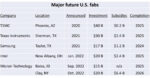
If we assume Intel does get the first 6 High NA tools as suggested we would imagine that Intel Portland will get at least the first two tools with other tools following in 2024 going to Arizona and/or Ohio.
Of the other four tools, maybe at least two to three to Samsung with TSMC getting one or two tools.
Its our guess that TSMC will likely push multi-patterning current EUV harder rather than jump to High NA right away.
There are numerous industry suggestions that High NA EUV tools are going to be difficult to cost justify versus multi-pattern existing EUV tools. This could either be a smart move by TSMC or a mistake…time will tell. From Intel’s perspective they have no choice but to push hard as their slowness to EUV in the past was one of the reasons that TSMC raced past them in Moore’s law.
Its clear that Intel does not want a repeat of what happened with the original EUV tools and thus committed early to ASML to get the first copies of High NA Tools as announced over a year ago.
If High NA does indeed pan out, this would be the “leap frog” that Intel needs to catch up.
If our guess of 15 tools in 2025 is close, we would expect the share between Intel, Samsung and TSMC to be a bit more even along with a tool for IMEC in Europe, who works closely with ASML, likely getting one as well for R&D.
In 2026, 20 tools is more of a toss up, between the big three foundry/logic makers, likely with the addition of a High NA tool for New York for R&D as recently announced.
We don’t expect memory makers to engage with High NA for the first several years as they are just starting to engage with regular EUV just now and remain 4 to 6 years behind foundry/logic need for EUV lithographic technology.
We would not be surprised that after 3 years of High NA shipments for Intel to have the majority of High NA tools much as TSMC has the lions share of current EUV technology.
A big but necessary bet for Intel
If Intel buys 6 High NA tools in 2024 that implys $2.1B to $2.4B in High NA tool capex alone. Thats a pretty big bet….but if it helps pay off in catching up to TSMC it will be money well spent. There is no choice, as to not do so would relegate Intel to a trailing and at best, if lucky, equal position with TSMC.
High NA will get into production faster than standard EUV did
Although there are significant differences between EUV and High NA EUV tools, the basic concepts are the same. Its not the quantum leap that EUV was over ARF immersion.
At $350 to $400M a copy, chip makers are going to need to put those new tools to work as quickly as possible.
They are also going to have to focus (pardon the pun) on getting an economic return on single pattern High NA versus multi pattern standard EUV which is probably not a slam dunk in the beginning just as EUV was hard to prove over multi pattern ARF immersion (there is still controversy as to thye cost advantage).
Does High NA finally leave China behind??
As we have seen with 7NM, China has been able to get EUV like fidelity using multi-patterning ARF immersion.
This work around seems extendable down to 5NM.
We have our doubts about extending ARF immersion down to 3NM in any sort of usable/economically feasible way. This would tend to suggest that those implementing High NA EUV will be beyond the reach of China’s fabs….at least for the foreseeable future.
The Stocks
We view this news if true, or even close to true, as a significant positive for both ASML & Intel. We however would not view it as a negative, just yet, for TSMC as they likely remain in a strong position in EUV overall.
We think that ASML and its stock could ride the High NA EUV wave throughout 2024 assuming no hiccups in production.
We would further suggest that the recent changes in the retiring CEO & CTO at ASML would not likely have happened unless and until High NA EUV was safely on its way and over any major technology humps or other issues as I doubt either one would likely retired on a weak note of a poor High NA roll out.
High NA is going out on a high note!
Although it may take a while for Intel to see the fruits of its High NA bet we think investors would be willing to overlook the negative impact of the spend required for High NA if the reward is regaining technology leadership…..
Have a great Holiday!!
About Semiconductor Advisors LLC
Semiconductor Advisors is an RIA (a Registered Investment Advisor),
specializing in technology companies with particular emphasis on semiconductor and semiconductor equipment companies. We have been covering the space longer and been involved with more transactions than any other financial professional in the space. We provide research, consulting and advisory services on strategic and financial matters to both industry participants as well as investors. We offer expert, intelligent, balanced research and advice. Our opinions are very direct and honest and offer an unbiased view as compared to other sources.
About Semiwatch
Semiconductor Advisors provides this subscription based research newsletter, Semiwatch, about the semiconductor and semiconductor equipment industries. We also provide custom research and expert consulting services for both investors and industry participants on a wide range of topics from financial to technology and tactical to strategic projects. Please contact us for these services as well as for a subscription to Semiwatch
Also Read:
AMAT- Facing Criminal Charges for China Exports – Overshadows OK Quarter
The Coming China Chipocalypse – Trade Sanctions Backfire – Chips versus Equipment
KLAC- OK quarter in ugly environment- Big China $ – Little Process $ – Legacy good