I attended a session on 2.5D silicon interposer analysis at DesignCon 2020. Like many presentations at this show, ecosystem collaboration was a focus. In this session, Jinsong Hu (principal application engineer at Cadence) and Yongsong He (senior staff engineer at Enflame Tech) presented approaches for interposer power modeling and HBM power noise prediction. The application was AI-focused, but the modeling approaches presented have broad applicability.
First, a bit about Enflame Tech. They are a startup with R&D centers in Shanghai and Beijing, China. They are developing AI-training platform solutions, including deep learning accelerator SoCs, PCIe boards and a software stack, targeting cloud service providers and data centers.
Since this design is focused on AI training, there is a 8-hi HBM2 memory stack on board to store the training data. An ASIC is integrated with the HBM2 through a silicon interposer. The ASIC contains a single integrated hard macro PHY that has eight independent channels with a total DQ width of 1,024, and the total number of signals is 3,300+. The figure below illustrates the overall package.

Two critical elements of this project are the design and simulation of the interposer. With regard to signal integrity, the wire length between the HBM and PHY is carefully chosen, as longer lengths need stronger drivers. High-speed signals are routed on M1/M3, with the shielding layer on M2. All signal routing is designed with a wire length difference of ±0.15%. The optimized physical configuration includes the signal width, trace spacing and shielding pattern, as shown below.

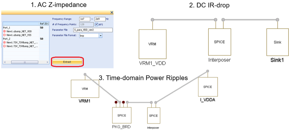
The AI chip has lots of HBM dies to do parallel calculations, and due to the significant scale of the micro-bump and C4 bump, it provides a level of modeling difficulties for both physical design and simulation engineers. With regard to power modeling of the complete interposer design, the Cadence Cadence Sigrity XcitePI Extraction tool was used to extract the SPICE netlist model. Model post-processing can be performed to validate the Z-impedance, IR drop and time-domain power ripples, as shown below.

Power noise was critical to ensure the stability of the HBM bus, and it was also challenging for the current tools to handle the tremendous HBM nets’ system signal and power simulation at the same time. The DesignCon presentation proposed two innovative methodologies to predict HBM power noise, using the Cadence Sigrity SystemSI and System Explorer tools for system time-domain simulation. The voltage multiplying method and the current-induced method were used for further power noise predictions, and the figure below illustrates a typical scenario. (Note that the acronym “CMF” means “current multiplying factor”.)


The benchmark measurements were performed by a test chip mounted on a reference board, and the measurement result showed that simulation predictions can correlate quite well with the predicted data.
 Lab measurement setup with test board
Simulated results with current-induced method
Measured results from lab 
Above all, these power modeling and noise prediction techniques may have broad applicability to many different types of 2.5D HBM-based silicon interposer designs.
Share this post via:


Comments
There are no comments yet.
You must register or log in to view/post comments.