
In our previous blog installments, we examined the ingredient for modeling the potential for interference between a 5G C-band base station and an aviation radar altimeter. Using candidate emissions models for the transmitter, wideband susceptibility models for a candidate radar altimeter receiver and antenna and propagation models for the wireless channel, we arrived at an analysis for a worst-case static arrangement of the systems. In addition, we explored a potential interference mitigation technique to eliminate the in-channel interference experienced by the radar altimeter which involved the design of a low-pass filter for the 5G base station.
Next, we add the component of real-world motion.
Dynamic Interference Assessment: Interference Simulation for an Airport Approach
To better understand the way interference might occur during a landing, takeoff, or go-around, we need to simulate the scenario as it unfolds during the flight process. This requires simulating the interference situation during the flight sequence in an accurate virtual environment involving a particular runway of interest.
Variations in the flight path and aircraft dynamics should be considered to determine worst-case scenarios for interference situations. These could include aircraft roll during landing due to wind gusts and turbulence, which could rotate the aircraft radar altimeter antenna to stare into a nearby 5G C-band base station on the ground. They could also include the impact of low-height base stations and propagation interactions with buildings and structures near the ground and around the airport.
Exploring these cases through experimental flight will be extremely costly and require control of the airspace and the electromagnetic spectrum around the airport during testing. Repeating these experiments for each of the variables listed above is simply untenable. But with modeling and simulation, we can explore these scenarios virtually and automatically, yielding the top scenarios that may warrant a final flight test for measurement-based validation. In fact without simulation, it is unrealistic to expect that all scenarios could be checked out experimentally within six months.
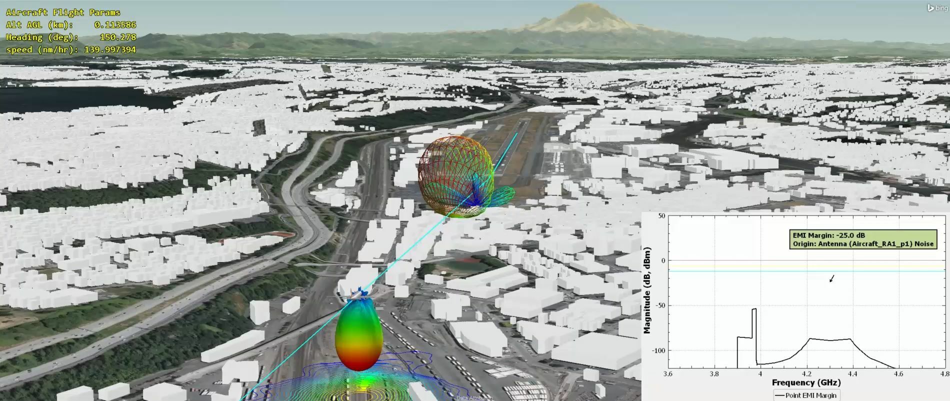
We have assembled such a simulation for a landing scenario near King County International Airport in Seattle, Washington. The figure below displays a landing scenario set up in the Ansys AGI Systems Tool Kit (STK) software. A notional long-range, wide-body aircraft is shown with the antenna pattern for an installed radar altimeter system. The landing trajectory is shown by the blue line on a south-by-southeast heading, which includes a taxi distance on the runway after landing. A 5G C-band base station antenna system is indicated directly under the flight path, with a mounting height of 9.5m, at or below roofline height of nearby buildings. AGI STK includes local terrain in scenarios, and even Mt. Rainier is visible in the distance.

Figure 11 – Landing approach scenario in AGI STK for an aircraft at King County International Airport in Seattle, WA. Simulated approach includes time-indexed flight dynamics, including aircraft pitch and roll effects on radar altimeter antenna pointing.
The aircraft will pass quite close to the 5G C-band base station in this scenario as shown in the figure below, but we have the freedom to place and move our base station antennas anywhere we wish, enabling rapid re-evaluation of the scenario.

Figure 12 – STK simulation shows landing geometry as aircraft passes close to the 5G C-band base station in the scenario. Projection of the radar altimeter gain contours can be seen on the ground beneath the aircraft.
The radios used in this simulation are identical to those defined in the static interference analysis, with the notable exception that the out of band saturation power level for our radar altimeter receiver is -30 dBm. It should be noted that this does not reflect the actual radar altimeter system installed on a particular aircraft, but is simply a notional system design based on the range of radar altimeter systems presented in the RTCA report to the FAA dated Oct. 2020.
Antenna-to-Antenna Coupling Captured with Physics
An important addition to this simulation is the use of high-fidelity physics simulation in computing the antenna to antenna coupling from moment to moment during the scenario. Recall that each antenna pattern has its basis in an electromagnetic simulation by Ansys HFSS and HFSS SBR+ to capture installed radar altimeter antenna effects as well as to capture an accurate radiation pattern for the 5G C-band phased array antenna.
The antennas are set into a model of the larger scattering environment that includes tower, buildings and large scattering structures around the airport, and the antenna-to-antenna coupling is sampled by HFSS SBR+. With this solution approach, potential masking and multi-path reflections by nearby buildings and structures are included in the physical path coupling from C-band 5G base station to radar altimeter antenna. S-parameter coupling data can be computed for a single frequency or a high number of frequencies sampled across any band of interest.
Interference Scenarios for the Current and Future 5G C-band Channel Implementations
The video below shows the complete landing scenario as simulated. In the inset graph, the electromagnetic interference (EMI) margin is illustrated. EMI margin represents the interfering transmitter spectral power present across the band of interest in the radar altimeter receiver front end, minus the receiver’s ability to reject that power. When the EMI margin (black curve) rises above the red line, the potential for interference exists and the receiver is either saturated (by a strong out of band signal) or de-sensitized (by a strong in-band signal). In addition, the EMI margin legend on the plot is color-coded to signify interference at any time. Green indicates an interference-free operation in the band, blue and yellow indicate EMI margins that have crossed indicator thresholds near interference conditions, and red indicates an interference event is occurring. The following simulation is conducted with a 5G C-band system operating in the current band of 3.7-3.8 GHz:
We can see strong interference occurs as the aircraft passes over the 5G C-band tower. The radar altimeter registers interference within its operational channel (centered at 4.2 GHz), and the receiver is also saturated from the strong 5G signals that are outside of the radar altimeter’s intended band of operation.
We can easily change the 5G C-band transmitter definition in our simulation to consider interference potential when the telecom operator uses the 80 MHz band from 3.9 to 3.98 GHz. Because it is closer to the radar altimeter band, we might expect that the potential for interference to the radar altimeter to be enhanced, and a quick re-simulation reveals this to be the case:
How to Fix to 5G C-Band Airport Issues
With modeling and simulation within scenario modeling, we can explore any radar altimeter, on any aircraft, at any airport runway, against any C-band 5G service towers that exist within a given radius of any airport. Given models of sufficient fidelity, this can all be done on a computer by individuals at any location without requiring flight time or impacting airport operations. Using simulation, we could:
- Explore or modify existing or planned radar altimeter systems
- Explore or modify 5G C-band base station performance parameters
- Examine cases where multiple 5G C-band base stations might exist
- Examine edge cases with respect to aircraft flight landing/takeoff dynamics (roll/pitch) which could result in antennas looking into one another’s high-gain zones
- Examine and explore reasonable limits on power, beams teering, effective isotropic radiated power (EIRP), and modifying 5G service tower keep-out zones around airports
- Provide guidance on flight planning for helicopters, private aircraft, delivery drones and more
Interference between the adjacent C-Band 5G spectrum services and radar altimeter systems is both predictable and solvable. Given sufficient fidelity in the underlying models, simulation represents a cost- and time-effective way to unobtrusively test and validate potential interference scenarios for any aircraft at any runway location. Scenarios can go beyond considering just 5G towers near the airport — with tools like AGI STK and Ansys Electronics Desktop we can look at any combination of wireless systems that might exhibit interference potential. This could become a key enabler for functions like low-altitude flight planning for helicopters, urban air mobility, drone delivery systems, and more.
Also read:
5G and Aircraft Safety: Simulation is Key to Ensuring Passenger Safety
5G and Aircraft Safety: Simulation is Key to Ensuring Passenger Safety – Part 2
5G and Aircraft Safety: Simulation is Key to Ensuring Passenger Safety – Part 3
Share this post via:


Comments
There are no comments yet.
You must register or log in to view/post comments.