As regular readers may know, every few months I check in with Cristian Amitroaie, CEO of AMIQ EDA, to see what’s new with the company and their products. In our posts so far this year we’ve focused on verification, and now I’m wondering how an integrated development environment (IDE) provides benefits to designers. They work on huge and complex projects, with millions of lines of code, a lot of IP reuse with no time to know every detail, multiple formats and languages, and tight deadlines. How can the IDE help? Does it have features of special value to designers?
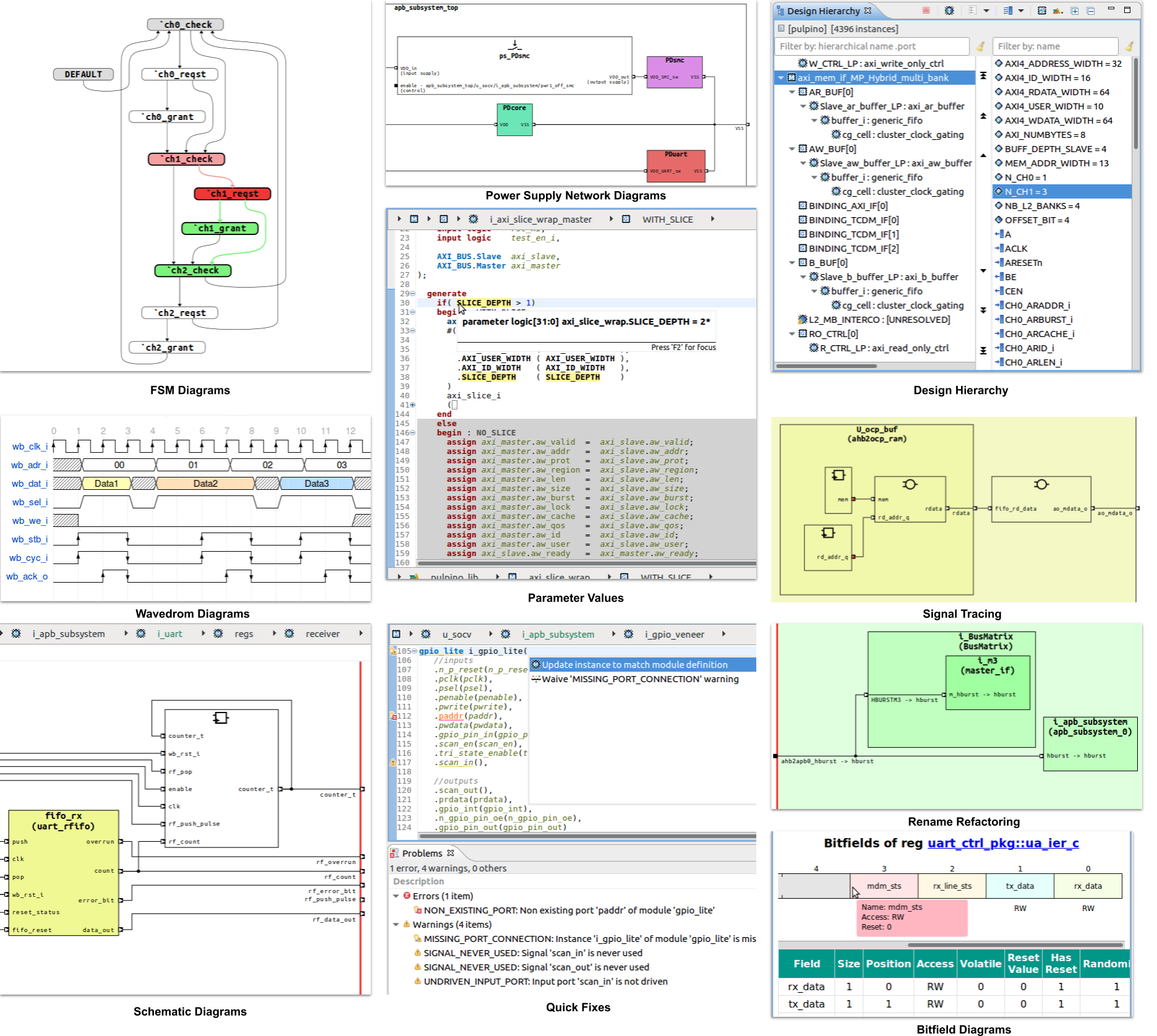
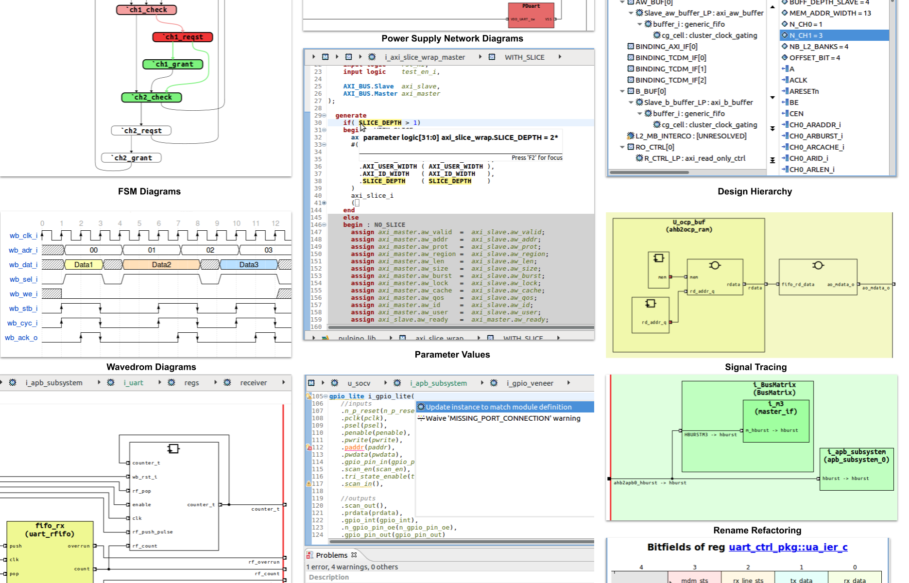
In Cristian’s view, one of the key features of AMIQ DVT Eclipse IDE is that it compiles and elaborates the RTL design code, so it has a complete view of how all the blocks fit together. For example, it computes `parameter’ values and `generate’ block results, showing them in all representations of the design. With its complete knowledge of the design structure, the IDE can offer a range of different views to help in understanding and modifying the design. Traditional text editors do not compile the design, so there is no way that they can provide the same capabilities as the IDE.
DVT Eclipse IDE incrementally compiles and elaborates code as the designer types it in, detecting a wide variety of common errors on the fly, ranging from simple typos to tricky syntax and semantic errors in RTL constructs. This helps ensure correct-by-construction coding by providing instant feedback and `quick fix’ suggestions. For example, if the user omits a port connection, misses a necessary item in a sensitivity list, or adds a signal that is never read or written, the IDE detects these issues and suggests fixes. SystemVerilog, Verilog, and VHDL are all supported equally well.
The IDE knows how all the design blocks are interconnected, so it is easy to navigate through the design and trace signals up and down complex hierarchies and across multiple blocks. Designers can click on a variable name in the editor to display readers and writers, or on a signal in the schematic view to show sources and destinations. Cristian pointed out that traditional text editors have no notion of signal connectivity between design files, so users must do many manual text searches to determine which files reference which signals.
The numerous hyperlinked views available make RTL navigation and editing much easier. Designers usually start with the design hierarchy view, which visually shows the complete scope of the fully elaborated design. The IDE provides breadcrumbs so that users always know where they are in the hierarchy. This is helpful when viewing or modifying code in the context-aware editor or exploring the automatically generated schematic diagrams. Project query views allow the designer to search for specific information, for example macro `define’ and `ifdef’ statements, and specific elements such as modules or module ports.
Other examples of visualizations include filtering or showing connections of a specific signal or instance, or connections between two or more instances. For designs with multiple power domains, the supply-network diagram shows power domains and how they are controlled. Both Unified Power Format (UPF) and Common Power Format (CPF) power-intent files are supported. Waveforms are another popular form of visualization for designers. DVT Eclipse IDE provides waveform specification and display via integration of the popular open-source WaveDrom tool.

RTL languages, especially SystemVerilog, are complex. Even experienced users may have trouble keeping all the syntax in their heads. The IDE helps by auto-completing code when possible and offering code templates for the designer to fill out. For example:
- If the designer types in a partial name, the IDE presents the options for auto-completion based on existing declarations
- If the designer references an enumerated type, the IDE suggests completions using the values defined for the type
- If the designer references a signal or module not yet declared, the IDE will offer to correct the name or add a declaration for a new name
- if the designer adds an instance of an existing module to the code, the IDE displays all the identifiers needed to connect the proper signals to the module inputs and outputs and to name the instantiated module
- If the designer defers some of the completion, the IDE can add `TODO’ or `FIXME’ reminder comments in the RTL code
When I asked Cristian about the most impressive capabilities for designers, he mentioned refactoring, which means modifying the code without changing its functionality. Refactoring improves code comprehensibility and maintainability, and can also yield better simulation performance and synthesis results. For example, DVT Eclipse IDE can extract an expression and create a new variable, making it easier to reuse the expression. Similarly, it can extract a section of code and create a new module. Users can also switch module instance argument bindings back and forth between named and positional, including the `.*’ construct in SystemVerilog.
Renaming signals or other elements of the design, especially across the entire design hierarchy as the signal name changes, is a form of refactoring that DVT Eclipse IDE does automatically at the click of a menu item. Changing a module declaration by renaming it or adding/subtracting/renaming ports means that all usages must also be updated in a consistent fashion. Again, the IDE does this automatically since it has a complete view of the design. The IDE can guide the designer in adding new ports to modules and connecting two modules using new or existing ports. All these automatic changes remain under user control, so each code modification can be reviewed and approved.
Finally, consistent formatting to common rules across a project or a company makes RTL code more readable. The IDE can automatically perform many such operations, including:
- Indenting the code according to scopes
- Indenting the code to vertically align constructs
- Trimming and compressing whitespace
- Wrapping lines or comments that are too long
- Inserting `begin’ – `end’ blocks
- Placing `if’ and `else’ constructs on new lines
- Placing module ports and parameters one or multiple per line
- Placing function and task arguments one or multiple per line
Cristian also noted that DVT Eclipse IDE supports many languages and formats beyond RTL and UPF/CPF, including SystemC, Verilog-AMS, Property Specification Language (PSL), the Universal Verification Methodology (UVM), and the Portable Stimulus Standard (PSS). Designers may have to deal with some of these from time to time. I enjoyed talking with Cristian and I’m pleased that AMIQ EDA provides so much support for designers. As I’ve said before, I can’t imagine being a design or verification engineer today without an IDE at my fingertips.
To learn more, visit https://www.dvteclipse.com.
Also Read
The Polyglot World of Hardware Design and Verification
An Important Step in Tackling the Debug Monster
Share this post via:


Comments
There are no comments yet.
You must register or log in to view/post comments.