RVN! 26 Banner revised (800 x 100 px) (600 x 100 px)

Supply Issues Limit 2021 Semiconductor Growth

Supply Issues Limit 2021 Semiconductor Growth
by Bill Jewell on 05-23-2021 at 10:00 am

Top Semiconductor Revenues 2021

Worldwide semiconductor shipments were $123.1 billion in 1Q 2021, up 3.6% from 4Q 2020 and up 17.8% from a year ago, according to WSTS. The 3.6% quarter-to-quarter growth was the highest for a first quarter since 1Q 2010, eleven years ago. The strong growth in 1Q21 implies strong growth in the following quarters and for the year 2021. However, supply constraints may limit semiconductor growth in 2021.

The table below show the top 14 semiconductor companies’ revenues in 1Q21, change versus 4Q20, and guidance (where available) for revenue growth in 2Q21 versus 1Q21. Of the 12 companies which have reported for 1Q21, three had revenue declines from 4Q20 – Intel, Qualcomm, and STMicroelectronics. These three companies all expect declines in 2Q21 revenues of about 4% from 1Q21. Intel and Qualcomm stated they were supply constrained. STMicroelectronics attributed the decline to seasonal trends.

The rest of the companies all had revenue growth, ranging from 2.4% for NXP Semiconductors to 12.1% for MediaTek. These companies all expect 2Q21 revenues to increase from 1Q21, ranging from 0.1% for NXP to about 14% for Micron Technology and MediaTek. NXP cited supply constraints for its cautious outlook. Thus, of the nine companies which provided guidance for 2Q21, four stated they are supply constrained.

How long will the semiconductor industry be supply constrained? A recent article on zdnet.com asserted it could take two years to work out all the semiconductor shortages. CNBC quoted an analyst who send the shortage may not be resolved until 2023. The CNBC article also cited a Gartner report that the shortage will last another six months. As we reported in our last newsletter, the automotive industry has been hit especially hard by the shortage. In a recent interview on CBS’ 60 Minutes TSMC chairman Mark Liu said his company can meet customer requirements for automotive semiconductors by the end of June, but supply chain issues could delay automotive production for several more months.

The global economy and key end equipment markets will drive increased semiconductor demand through at least 2021 and 2022. According to the International Monetary Fund (IMF) global GDP will bounce back from a 3.3% decline in 2020 due to the COVID-19 pandemic to a strong 6.0% growth in 2021. GDP growth is expected grow 4.4% in 2022, above the long-term trend. IDC projects smartphone units will rebound from a 6.7% decline in 2020 to 5.5% growth in 2021, moderating to 3.7% in 2022. The PC market grew 13% in 2020 as home-based work and education drove demand. IDC expects 2021 to be even stronger, with 18% PC unit growth. A correction in the PC market is forecast in 2022 with a 5% decline. Wards Intelligence / Morningstar project shipments of light vehicles will grow a robust 11% in 2021 after a 15% decline in 2020. Light vehicle growth will moderate to 7% in 2022, above the long-term trend. However automotive semiconductor shortages could limit 2021 growth.

Forecasting the 2021 semiconductor market is particularly difficult as the world recovers from the pandemic. Rebounding demand for electronics is offset by semiconductor shortages. Shortages will drive up some semiconductor prices, but others are set by long term contracts. Building a new semiconductor fab takes about two years, but in many cases, production can be increased at existing fabs in a relatively short time period.

Recent forecasts for the 2021 semiconductor market are in two camps. The December 2020 WSTS forecast was updated with final 4Q20 data, resulting in 10.9% growth in 2021. IDC’s May projection was 12.5% in 2021. IDC states robust growth in key markets for semiconductors will be offset by supply constraints. IC Insights believes the strong 1Q21 and moderate quarterly growth for the next three quarters will drive 19% semiconductor growth for the year.

Our latest forecast from Semiconductor Intelligence is similar to IC Insights, with a projection of 20% growth in 2021. We believe strong demand will drive high growth, even though shortages may limit the upside. Without supply constraints, potential growth could be in the 25% range. We expect semiconductor growth to moderate to 12% in 2022, still above the long-term trend growth of 6% to 7%.

Semiconductor Intelligence is a consulting firm providing market analysis, market insights and company analysis for anyone involved in the semiconductor industry – manufacturers, designers, foundries, suppliers, users or investors. Please contact me if you would like further information.

Also Read:

Automakers to Blame for Semiconductor Shortage

Electronics Back Strongly in 2021

Semiconductors up 6.5% in 2020, >10% in 2021?


AMAT Nice Beat Strong Growth for Both 2021 & 2022

AMAT Nice Beat Strong Growth for Both 2021 & 2022
by Robert Maire on 05-23-2021 at 6:00 am

Applied Materials Q2 2021 1

-Strong beat & guide- WFE up in 2021 & 2022-$160B combined
-Taking share in conductor etch & CVD
-Traditional Moore Scaling – No More?
-Foundry Logic leads followed by DRAM with weak NAND

Nice beat & guide & raise
Applied reported revenues of $5.58B with GM of 47.5% resulting in non-GAAP EPS of $1.63. Street expectation was for $5.41B and EPS of $1.51.
Guidance for the current quarter was $5.92B+-$200M and EPS range of $1.70-$1.82 versus street expectations of $5.53B and EPS of $1.56.

Financial results continue to improve nicely year over year with system sales up 50% year on year, great strengths in service and packaging at $800M

Second half 2021 to be up and 2022 also up
Applied went way ahead of its normal conservative guidance to say hat the second half of 2021 will be up over the first half and 2022 will be up over that.

WFE estimates increased for two years
Applied Materials upped the ante in WFE projections from the low $70’sB to the High $70’sB for 2021 and both years combined to be at least $160B which implies continued growth into 2022 which we take as a very bullish statement.

We think Applied management obviously has enough confidence in orders going forward to predict almost two years of growth. That kind of confidence in this industry is highly unusual so we think they are getting very strong signals over the long term from customers including some very large capex spending projections from the largest players.

China business improves
Applieds China revenue was up from last quarters $1.138B to the reported quarters $1.844B gong from 29% of revenues to 33% of revenues and the largest geographic segment of their business.

Obviously Applied is not getting hurt by any embargo on SMIC or others in China as China continues to ramp up equipment purchases more than any other place on the planet.

Share gains in conductor etch & CVD
Applied pointed out share gains in both Conductor Etch & CVD and further pointed to overall share gains in the semiconductor equipment market as compared to their peer group. We would assume that a fair amount of the gains came at the expense of Tokyo Electron.

Packaging at $800M in business looks like a segment of future strong growth as packaging is one of the key “more than Moore ” areas that will see increased spend on heterogeneous chiplet packaging.

Service business continues to grow very strongly and is emerging as a strong anti cyclical source of revenue.

Moore’s scaling , no more?
Applied suggested on the call that traditional geometric Moore’s Law scaling is on the decline (which we would agree with). Their view is that their offerings are favored by non-traditional Moore scaling alternatives which we would tend to agree with.

How far, how fast and how much will be spent on non-traditional scaling remains to be seen but we think EUV spend , which is traditional geometric scaling, will remain huge and get even bigger over time.

The stock
Applied has pulled back since its peak in the $140’s around the time of its analyst meeting. It closed yesterday at around $130 and the excellent report and very strong long term outlook could help it regain much of the value that came out of Applied and the rest of the semi equipment stocks. We would continue to be owners and might even get a bit more aggressive on some of the smaller cap or sub supplier names in the space.

About Semiconductor Advisors LLC
Semiconductor Advisors is an RIA (a Registered Investment Advisor), specializing in technology companies with particular emphasis on semiconductor and semiconductor equipment companies. We have been covering the space longer and been involved with more transactions than any other financial professional in the space. We provide research, consulting and advisory services on strategic and financial matters to both industry participants as well as investors. We offer expert, intelligent, balanced research and advice. Our opinions are very direct and honest and offer an unbiased view as compared to other sources.

Also Read:

You know you have a problem when 60 Minutes covers it!

KLAC- Great QTR & Guide- Foundry/logic focus driver- Confirms $75B capex in 2021

Lam Research performing like a Lion – Chip equip on steroids


Podcast EP21: Leading Edge Analog Design

Podcast EP21: Leading Edge Analog Design
by Daniel Nenni on 05-21-2021 at 10:00 am

Dan is joined by Mark Williams, founder and CEO of Pulsic. The application of shape-based routing to automate analog design is explored. Pulsic’s revolutionary new automated analog layout system, Animate is also discussed. With this system, multiple, high quality, fully routed layouts can be created in minutes from an OpenAccess schematic. The unique business model being deployed by Pulsic is also outlined. Mark concludes with a discussion of the future of analog design.

The views, thoughts, and opinions expressed in these podcasts belong solely to the speaker, and not to the speaker’s employer, organization, committee or any other group or individual.


CEO Interview: Toshio Nakama of S2C EDA

CEO Interview: Toshio Nakama of S2C EDA
by Daniel Nenni on 05-21-2021 at 6:00 am

Toshio Nakama SemiWiki

Toshio Nakama is the founder and the CEO of S2C and also a strong advocate of FPGA accelerated ASIC/SoC design methodology. Mr. Nakama devotes much of his time in promoting scalable Prototyping/Emulation hardware architecture and defining automated software specifications. He first started his career at Altera in 1997 and served in technical and sales management roles at Aptix Corporation from 1998 to 2003. He co-founded S2C in Silicon Valley in 2003 and established R&D and manufacturing teams in Shanghai, China in 2004. S2C was acquired by SMiT Group in 2018 and continues to be a leading global provider of FPGA prototyping solutions. Mr. Nakama holds a bachelor’s degree in Electrical Engineering from Cornell University and an EMBA degree from CEIBS.

What brought you to the semiconductor industry?

I was first introduced to FPGAs in my Digital Circuit Design course at Cornell and I was immediately drawn to the programmability and the vast application aspects of FPGAs. This led me to join Altera and later Aptix, who was known for FPIC (Field Programmable Interconnect Chips). FPICs were often used in conjunction with FPGAs as solutions for reconfigurable computing and IC design emulation. The immense value such as convenience, productivity and flexibility demonstrated by these programmable devices eventually became my mission – to push the limits of what FPGA prototyping can do and to make the IC verification process easier, faster, and more efficient for IC designers.

Can you tell us about the origin of S2C?

Two other ex-Aptix principals and I, together with another finance professional – we pooled our money and founded S2C in 2003. At the time, most of the focus on IC design verification was with software simulation and hardware emulation. FPGA-based prototyping on the other hand was yet to be a mainstream verification methodology and it was only accessible by large design houses with the budget and resources to materialize a prototyping architecture. We recognized the value of prototyping and the power to accelerate time-to-success for SoC design companies.

Also at the time, we saw a new wave of Asian firms, as well as Asian design centers for US/European companies taking shape. We expected that these new companies were to be more open to new ideas and new EDA tools from a new innovator. In 2004, we set up a R&D center in Shanghai to gain better access to talent pools for upcoming product developments and to better connect and service the Asian customers. The latter is particularly important as the methodology behind FPGA-based prototyping was fairly new and there would be a fair amount of customer handholding required.

From the start, S2C was not just another “FPGA board” vendor but we aimed to bring convenience, productivity, and flexibility to shorten the verification cycle. One key challenge at hand when we started was the development of tools and IPs specifically for FPGA-based prototyping. In particular, FPGA tools were different, even foreign to most ASIC designers. S2C’s first task was to develop a complete methodology – a set of tools and IP that would not only make FPGA-based prototyping more productive but would also smooth out the transition of a design from the prototyping stage back into an EDA flow bound for an SoC.

In February 2005, S2C filed its patent for a “Scalable reconfigurable prototyping system and method.” It described a system for automating validation tasks for SoCs, with a user workstation, data communication interface, and an emulation platform with multiple FPGAs plus interfaces to a real-world target system. In May 2005, S2C announced its first product the IP Porter system at DAC. Beta customers working with the product estimated their design time was cut by 3 to 6 months.

What markets and what are some of the customer challenges does S2C address today?

As mentioned, our key mission has always been to help customers shorten their time-to-success through hardware-accelerated verification solutions. We now see that many of the high complexity ASIC designs today come from markets such as AI, Datacenter, Multimedia, Networking and Automotive These are often hyperscale multi-core SOC designs with time consuming software development and testing requirements. FPGA-based prototyping is the optimal solution to provide a high performance platform not only for hardware validation but also as an early prototype to enable software teams to conduct hardware/software co-development and co-testing.

To target hyperscale designs, we launched Prodigy Logic Matrix in late 2020. Logic Matrix is a high-density FPGA prototyping platform designed for multi-system expansion to address the needs for both capacity and performance. Earlier this quarter, we also announced MDM Pro, the latest member of our Multi-FPGA debugging solution. MDM Pro increases the concurrent deep trace capability to 8 FPGAs and supports faster sampling rates and deeper trace capacity. We are also continuously refining our partitioning software to and releasing more off-the-shelf daughter cards to simplify the setup of customer’s prototyping environment and to enable testing done via real-world data.

What is the S2C competitive positioning?

There is a combination of things which is raising S2C to new heights. With close to 20 years of know-how and proven track record, solid products, close customer relationship and outstanding service, we are doing extremely well in China, where the IC design activities have grown rapidly over the last few years. These customers not only help to provide scale of economy to lower cost, they also in turn help to provide feedback to enable us to continuously innovate and to roll our new products to match the market demand – not only for China customers but for customers worldwide, at good value.

If we compare ourselves to the Big 3, while S2C may not have the same comprehensive EDA coverage as they do, we are however more agile and more flexible. We aim to service and provide customization to help address customer demands. If we compare S2C to other tier two vendors and BYO (Build Your Own), S2C’s products are proven, more robust, more comprehensive. Together with scale of economy, we deliver high values to our customers.

What does the next twelve months have in store for S2C EDA?

2021 will be an exciting year for S2C. On the hardware side, we are rolling out a higher capacity Logic Matrix LX2 in Q3 and our first emulator platform in Q4. On the software side we will be adding RTL partitioning and serdes based pinmux support in a few months to better service hyperscale designs.

www.s2ceda.com

Also Read:

COO Interview: Michiel Ligthart of Verific

CEO Interview: Srinath Anantharaman of Cliosoft

CEO Interview: Rich Weber of Semifore, Inc.


Upping the Safety Game Plan for Automotive SoCs

Upping the Safety Game Plan for Automotive SoCs
by Rich Collins on 05-20-2021 at 10:00 am

Upping the Safety Game Plan for Automotive SoCs

Thanks to advanced hardware and software, smart vehicles are improving with every generation. Capabilities that once seemed far-off and futuristic—from automatic braking to self-driving at the very pinnacle—are now either standard or within reach. However, considering how vehicle architectures have continued to evolve, the way that safety and security are being addressed also must change.

Vehicles have typically been designed with dozens of discrete microcontrollers, each managing a separate function, from window operations and door locks to engine control. Now, we’re seeing increased centralization, with large systems-on-chip (SoCs) managing wider categories of functions. For example, one SoC might be dedicated for all vehicular communications, another for networking, and so on.

Considering the size and complexity of today’s automotive SoCs, a sound approach is to really understand the safety architecture and develop a safety plan first, before defining the vehicle’s architecture. The safety plan should be guided by automotive functional safety standards, namely ISO 26262. Developed by the International Organization for Standardization in conjunction with the International Electrotechnical Commission (IEC), ISO 26262 mandates a functional safety development process, from specification through production release, for automotive OEMs and suppliers to follow and document in order to have their devices qualified to run inside commercial vehicles. By following ISO 26262, automotive OEMs and suppliers provide assurance that their devices will perform as intended, when intended. The standard outlines a risk classification system, based on Automotive Safety Integrity Levels (ASIL), with the aim of reducing possible hazards caused by malfunctions in electrical and electronic systems. There are four ASILs, each based on the probability and acceptability of harm. ASIL D, the highest degree, is most relevant to safety-critical applications like Advanced Driver Assistance Systems (ADAS). ASIL D will only continue to grow in importance as vehicles incorporate increased levels of autonomous driving capabilities.

Another framework for which automotive safety devices must comply comes from AUTOSAR, which was founded in 2003 to create an open and standardized automotive software architecture and has defined the use of C++14 for safety-critical environments. Also important in the early phases of safety planning is consideration of cybersecurity measures. The U.S. National Highway Traffic Safety Administration (NHTSA) has an updated 2020 draft of its Cybersecurity Best Practices for the Safety of Modern Vehicles document, which mandates compliance from anyone manufacturing or selling vehicles in the U.S. The organization considers vehicles to be “cyber-physical systems and cybersecurity vulnerabilities could impact safety.”  Other automotive security standards, such as ISO/SAE 21434, are in the early stages, but look to help drive best practices in developing security architectures for safety-critical SoCs.

Defining a Safety Plan for Automotive SoCs

A strong safety plan outlines and defines all of the safety mechanisms for a given component, including compliance with AUTOSAR standards and ASIL levels. It’s also important to factor in cybersecurity at this stage. A key component of executing a safety plan is the implementation of a functional safety manager.

When designing with discrete microcontrollers, automotive engineers tend to utilize discrete safety managers from their chip vendors. With an SoC-centric approach, it’s important from safety and performance perspectives to have a dedicated safety manager integrated on the SoC to initiate, manage, and schedule boot-up and mission-mode tests. A large SoC tends to have multiple processor cores. Devoting a dedicated processor core to serve as a safety manager prevents periodic safety checks and monitoring tasks from interfering with normal SoC operations, while also isolating safety code from non-safety application software. Other benefits include reduced power and area, lower system costs, and enhanced real-time response rates. The figure below illustrates the evolution from a multi-chip to a single-chip solution for an advanced driver assistance system (ADAS) application.

Meeting Functional Safety Software Requirements

With hardware comes the need for software, which is where functional safety manager software comes into play. Having an integrated functional safety manager provides many benefits, including:

  • Independent and deterministic safety decision-making across various subsystems of a complex automotive SoC, with the option of having a dedicated safety routine per subsystem or IP module
  • Faster time-to-market through substantially reduced software overhead

Automotive software developers can choose to write their own functional safety software. But, clearly, this requires an investment in time and resources. Alternatively, they can turn to a proven, off-the-shelf software library. An effective safety management software library consists of:

  • A test manager that plans and schedules test execution, interacts with test providers for full SoC test coverage, works in boot and mission modes, and manages fault injection
  • A fault manager that collects and post-processes raw fault notifications from SoC components and converts them into safety alarms; maintains severity, hierarchy, and aggregation of safety alarms; generates software-visible safety alarms via callbacks or non-maskable interrupts; and asserts hardware fault notification or reset signals
  • A watchdog manager that handles internal watchdogs to control program execution flow, handles external watchdogs to guarantee system-level fault detection time intervals, and interacts with the test manager to provide the seed for test signature generation

Introducing ASIL-Certified Software

Synopsys recently unveiled a set of ASIL-certified ARC® embedded functional safety software components for safety-critical applications:

  • A functional safety C runtime library provides building blocks for safety-critical applications
  • Software test libraries provide a mechanism to achieve ASIL certification where redundant hardware isn’t required
  • Fault, watchdog, and test management components enable a fully programmable SoC safety management solution
  • Example MCAL and complex drivers ease integration into an AUTOSAR environment

The functional safety software stack runs on ASIL D-compliant DesignWare® ARC functional safety processor IP to simplify safety-critical automotive SoC development and accelerate ISO 26262 qualification. To facilitate development, debugging, and optimization of embedded software for ARC processors, we offer ASIL D-certified ARC MetaWare Development Toolkit for Safety. The combination of the software stack and the processor IP can save several staff years of development time.

The ARC software stack and processor IP are part of a larger portfolio of Synopsys solutions for automotive design. With a long history of automotive expertise, Synopsys provides many other resources to help hardware designers and software developers comply with automotive functional safety requirements:

Planning for safety early in the vehicle design process can pay big dividends for you and, ultimately, your customers. And by executing a safety plan with ASIL-compliant electronic design automation (EDA) tools and IP, along with robust software security testing solutions, you can save time and effort in the process of creating smarter, safer cars.

In Case You Missed It

Catch up on some other recent automotive-related blog posts:


Architecture Wrinkles in Automotive AI: Unique Needs

Architecture Wrinkles in Automotive AI: Unique Needs
by Bernard Murphy on 05-20-2021 at 6:00 am

Baidu versus Mobileye min

Arteris IP recently spoke at the Spring Linley Processor Conference on April 21, 2021 about Automotive systems-on-chip (SoCs) architecture with artificial intelligence (AI)/machine learning (ML) and Functional Safety. Stefano Lorenzini presented a nice contrast between auto AI SoCs and those designed for datacenters. Never mind the cost or power, in a car we need to provide near real-time performance for sensing, recognition and actuation. For IoT applications we assume AI on a serious budget, power-sipping, running for 10 years on a coin cell battery. But that isn’t the whole story. AI in the car is a sort of hybrid, with the added dimension of safety, which makes for unique architecture wrinkles in automotive AI.

I’ve mentioned before that Arteris IP is in a good position to see these trends because the network-on-chip (NoC) is at the heart of enabling architecture options for these designs. Currently Arteris IP is in the fortunate position to be the NoC intellectual property (IP) of choice in a wide range of hyperscalar and transportation applications, particularly those requiring AI acceleration. For example, Baidu with their Kunlun chip for in-datacenter AI training versus Mobileye with their EyeQ5 chip targeted at mobile autonomy for levels 4 and 5. Each is quite representative of its class, in constraints and architecture choices, granting that AI architecture is a fast-moving domain.

Datacenter AI Hardware

All hardware is designed to optimize the job it must do. In a datacenter, that can be a pretty diverse spectrum of pattern recognition algorithms. Therefore training/inference architectures most often settle on arrays of homogenous processing elements, where the interconnect is a uniform mesh between those elements (perhaps also with E/W sides or N/S sides connected).

These architectures must process huge amounts of data as fast as possible. Datacenter services and competitiveness are all about throughput. The accelerator core will often connect directly to high bandwidth memory (HBM) in the same package for working memory to maximize throughput. The design includes necessary controller and other SoC support but is dominated by the accelerator.

Performance is king, and power isn’t a big concern, as you can see in the table above for the Kunlun chip.

Automotive AI Hardware

Automotive AI is also designed to optimize the job it must do, but those tasks are much more tightly limited. It must recognize a pedestrian, lane markings or a car about to pass you. Such designs need to be more self-contained, handling sensors, computer vision, control, potentially multiple different accelerators, plus an interface to the car network. A more heterogeneous design with a mesh network won’t help.

Even within the accelerators, arrays of processing elements with mesh networks are far from ideal. Architects are shooting for two things: lowest possible power and lowest possible latency for safety. Both of which you can improve by keeping as many memory accesses as possible on-chip. Local caches and working memories must be distributed through the accelerator. Array/mesh structures are also not ideal for latency. These structures force multi-hop transfers across the array where an automotive application may want to support more direct transfers. An array of processing elements is often overkill. A more targeted structure no longer looks like a neat array.

You can further reduce latency through broadcast capabilities. These fan out critical data across the network in one clock tick, becoming faster by departing yet further from that simple array/mesh structure.

By default, AI accelerators are power hogs. Huge images are flowing through big arrays of processors, all constantly active. Dedicated applications can be much more selective. Not all processors or memories have to be on all the time; they can be clock gated. You can also selectively clock gate the interconnect itself. This is an important consideration because there can be a lot of long wires in these interconnects.  You can manage dynamic power through careful design. Augmenting this with intelligent prediction of what logic you want on and when.

Automotive AI and Safety

Safety isn’t a big consideration in datacenter AI hardware, but it’s very important in auto applications. All that extra memory on-chip needs error code correction (ECC) to mitigate the impact of transient bit flips, which will likely further complicate timing closure. Typically, safety mitigation methods will increase area and may negatively impact yield.

More generally, Kurt Shuler, vice president of marketing at Arteris IP, likes to say that an SoC (micro-)architect should pay close attention to any project management topic in safety which might impact architecture. Safety-critical designs start with pre-agreed lists of Assumptions of Use (AoU) from IP suppliers. If they start checking these late in design, they can get into a lot of trouble. They need to understand these AoUs up-front as you are developing the architecture. These are things suppliers can’t change easily. Save yourselves and your suppliers all that hassle. Read the instructions up front!

You can access the Linley presentation HERE.

Also Read:

Arteris IP Contributes to Major MPSoC Text

SoC Integration – Predictable, Repeatable, Scalable

Arteris IP folds in Magillem. Perfect for SoC Integrators


Chip Design in the Cloud – Annapurna Labs and Altair

Chip Design in the Cloud – Annapurna Labs and Altair
by Kalar Rajendiran on 05-19-2021 at 10:00 am

Compute Farm Growth

The above title refers to a webinar that was hosted by Altair on April 28th. Chip design in the cloud is not a new idea. So, what is the big deal with the above title. Sometimes titles don’t reveal the full story. Annapurna Labs happens to be an Amazon company. It used to be an independent semiconductor company that was acquired by Amazon in 2015. So why not say, “Chip Design in the Cloud – Amazon and Altair” or “Chip Design in the Cloud – AWS and Altair.” The key phrases are “food for thought”, “eagle eyes”, and “optimized scaling.” After reading this blog you will know why.

The webinar was delivered by Andrea Casotto, Chief Scientist at Altair, Zohar Levy, HPC Project Manager at Altair and David Pellerin, Head of Worldwide Business Development for Infotech/Semiconductor Amazon Web Services.

Straight off the bat Andrea shocked the audience by stating that many companies are repatriating back from cloud to on-premises. He presented some cost overruns stats to back up his shocker statement. Of course, he quickly pointed out the reasons behind those overruns and introduced the solution as well. The solution is Rapid Scaling.

Rapid Scaling is Altair’s patented approach to implementing cloud elasticity. It is a feature within their Accelerator software and was developed by Altair when working with Annapurna Labs. This feature helps bring cloud services cost as close as possible to demand by not asking for more hardware than is needed to complete the workloads. It accomplishes this by:

  • Categorizing similar characteristics jobs into workload buckets and calculating the speed at which each bucket can get scheduled
  • Monitoring EDA license dependencies and availability of required licenses and not asking for hardware until the licenses become available
  • Enforcing customer specified cost-schedule limits by not launching workloads and/or requesting more hardware resources when cost-tally gets close to preset limits
  • Executing workload scheduling policies and accordingly switching between on-demand instances and spot instances to optimize cost, AND
  • Stopping the Compute Farm growth at the optimal point knowing (based on its estimation) that all jobs still remaining in the queue will get dispatched to hardware within customer specified time window. Refer to Figure 1. In this example, the Compute Farm growth stops even when there are 100 jobs in the queue [vertical red line cutting through the graphs]. That is because the Accelerator estimates that all jobs in the queue can be dispatched within 10 minutes to existing hardware. The 10-minute window was set by the customer and is a configurable parameter.

Figure 1:

Andrea continued by discussing the different operating systems, processor architectures and instance types currently supported by Rapid Scaling, and then passed the baton to Zohar.

Zohar demonstrated Annapurna Labs’ live production environment for semiconductor design, without and with Rapid Scaling feature enabled. Refer to Figure 2 for Altair Accelerator Architecture and operating environment. You will have to see the live demo to see the benefits presented visually on an hourly, daily, weekly or monthly time scale. Suffice it to say the demo clearly demonstrated cloud elasticity.

Figure 2:

David followed Zohar with a talk summarizing Amazon’s experience in designing chips in the cloud.

He discussed how and why Amazon got into designing custom silicon, how these initiatives help its AWS customers and the expansion in the number and types of instances offered. Graviton/Graviton2, Inferentia, Trainium, and Nitro System were listed as examples of custom silicon built at Amazon Labs that are powering many of the purpose-built AWS instances. He shared case study snapshots of customers such as MediaTek, Qualcomm and Arm who have benefitted by EDA on AWS Cloud for designing their chips and IP.

David also highlighted how ARM-based instances are fast becoming a good high-performance alternative to traditional x86-based instances for EDA on the cloud. He spotlighted the recently announced X2gd Arm-based instance as particularly suited for EDA workloads as these instances have a high amount of memory.

David also touched on Amazon’s own EDA journey to AWS Cloud as they migrated (refer to Figure 3) from Annapurna Labs’ on-prem EDA flow to everything on AWS Cloud, except for emulators.

Figure 3:

David closed his talk with a thought on how customers who have on-prem EDA flow could explore hybrid EDA orchestration. He pointed out that a tool such as Altair’s Accelerator knows when to tap into the Cloud for certain types of instances or for spot instances or for EDA licenses to optimize cost.

The webinar closed with a Q&A segment during which some excellent questions were fielded.

Now You Know

The Annapurna Labs team has a penchant for scaling obstacles. The word Annapurna refers to a mountain range in the Himalayas with a number of tall peaks. The Annapurna Labs logo showcases that. The etymology of the word Annapurna tells us that it stands for abundant food. True to its name, Annapurna Labs has certainly provided some food for thought with respect to efficiently scaling the peaks, valleys and plateaus of semiconductor design workloads utilizing AWS cloud services.

The word Altair stands for eagle as per etymological roots. Altair keeps an eagle eye on dependencies, resources and costs through its scheduling software equipped with patented rapid scaling technology. The result is very cost-effective scaling for Annapurna Labs. One case study derived a 50% cost savings compared to not leveraging the rapid scaling feature.

Summary:

Altair’s Accelerator with its patented Rapid Scaling feature is a cost-conscious job scheduler proven to meet the compute demands of the semiconductor and EDA workloads in the cloud. It is capable of launching and managing millions of jobs on a daily basis.

Anyone designing semiconductor chips can benefit from Altair solution when designing in the cloud. It is currently supported on AWS cloud. I recommend you listen to the entire webinar and then discuss with Altair on ways to leverage their solution for your benefits.

Also Read

Webinar: Annapurna Labs and Altair Team up for Rapid Chip Design in the Cloud

Altair Expands Its Technology Footprint with I/O Profiling from Ellexus

Altair HPC Virtual Summit 2020 – The Latest in Enterprise Computing


NetApp Simplifies Cloud Bursting EDA workloads

NetApp Simplifies Cloud Bursting EDA workloads
by Daniel Nenni on 05-19-2021 at 6:00 am

NetApp Cloud Bursting

Why burst EDA workloads to the cloud
Time to market challenges are nothing new to those of us who have worked in the semiconductor industry.  Each process node brings new opportunities s along with increasingly complex design challenges. 7nm, 5nm and 3nm process nodes have introduced scale, growth, and data challenges at a level previously unheard of, particularly for backend design processes.

Design teams are looking to hyperscale clouds providers like AWS, Azure and Google Cloud as a way of providing the on-demand scale and elasticity required to meet the time to market challenges.  An ever-increasing number of semiconductor companies have either evaluated or are regularly using the cloud for burst capacity. Runtime analytics as well as Spot pricing has lowered cost barriers of Cloud by enabling jobs to run on the lowest cost servers for the required job and for the right amount of time.  This has nearly removed the cost barriers to enable increased use of cloud – particularly for burst or peak periods of the design process.

Increased use of AI and GPU enabled EDA tools are driving a need to include more and more GPU enabled servers in the flow.  The cloud enables design teams to quickly spin up the right mix of server types to match the workloads based on feature requirements and cost.

Bursting cloud might seem like the right solution but data mobility and data transfer to and from the cloud makes bursting outside of traditional on-prem data centers challenging due to the size and gravity of data.

Example workloads burst to the cloud
Front-end verification jobs are often the first jobs companies attempted to burst to the cloud.  The ever-increasing number of simulations, Lint, CDC, DFT and power analysis runs at the block, sub-system and full chip level are as many as 20k-50k jobs in a nightly run.  The more jobs that can be run in parallel, the faster the jobs will finish, and the faster issues can be detected and resolved.

The server requirements of these jobs can vary widely from very small IP level jobs that take just a few minutes to Fullchip runs which require large core count, high memory servers.  The range of jobs are ideal for the cloud where the wide range of server types and sizes can match the requirements of each job.  Frontend jobs tend to be tolerant to job failure, preemption, and restart, which makes them ideal for running on lower cost Cloud SPOT instances.

AWS Quote “You can launch Spot Instances on spare EC2 capacity for steep discounts in exchange for returning them when Amazon EC2 needs the capacity back. When Amazon EC2 reclaims a Spot Instance, we call this event a Spot Instance interruption.  You can specify that Amazon EC2 will Stop, Hibernate or terminate interrupted Spot Instances (Terminate is the default behavior).”

New AI driven workflows like DSO.ai lend themselves to burst to cloud use models.  Instead of doing a single run, analyzing results, then tweaking parameters and re-running.  These new workflows kick off 30-40 runs in parallel all with different optimization parameter settings, then AI analyzes which of the runs had the best outcomes and then uses those results to seed the next 30-40 runs.

Designs that have 20 or more blocks/subsystems/Fullchip runs will then require 30-40 runs per analysis for a 30-40x increase in the number of jobs and data required to run the analysis.  The tradeoff of increased compute demand, supplied by additional cloud compute capacity, to quickly zero in on improved PPA results in a fixed schedule can be achieved.  Fabs are also getting in on the burst to cloud use model.  OPC (Optical Process Correction), RET (reticle enhancement tech) and MDP (mask data prep) jobs are some of the most compute intensive and time to market sensitive jobs in the chips design cycle. Cloud scale and availability enables fast turn-around and speeds chip production.

Challenges with Bursting to Cloud
Setting up an automated burst to cloud use model is the first challenge.  Cloud providers have EDA reference architectures for setting license servers, grid engines (LSF, Grid, and SLURM) and providing automation for provisioning the compute, network, and storage infrastructures. The FlexLM based license setup is typically unchanged from on-prem or can even use the same on-prem license server.  The biggest challenge is often figuring out which data needs to be replicated (copied) to the cloud to run the workflows.

Most design flows point to a myriad of different design files scattered across many different volumes of data.  Tools, libraries, 3rd party IP, CAD flow scripts, RCS files (like P4, ICManage, etc.) and even in some files in users’ directories.  The first challenge is figuring out WHAT files (or volumes) of data are needed for the flow which is being burst to the cloud.  The second obvious issue is HOW do you transfer these files to the cloud.

Sadly, there is no simple solution to the WHAT Files question.  The obvious RCS, tools and library files are typically easy to identify. The others might require running the job in the cloud and then repeated trial and error, copy missing files, repeat.  This can be very challenging and time consuming particularly if you must copy lots of data.

The other issue is the size of the data.  The easy thing to do is to copy the entire /mnt/tools/ directory to the cloud.  But then do you really need every tool and version of tool, or maybe just the latest or the specific versions your flow requires.  Simply copying ALL files will result in long data transfer times and increased storage costs.

Then there is the question of HOW to copy the files to the cloud.  Rsync, ssh scp, gtar/FTP, or even reinstall the tools in the cloud.  All these methods work and are tried and true, but then how do you keep the cloud data in sync with the on-prem data.  Tool versions and new libraries are always being updated, how do you ensure the environment you setup and got working in the cloud will work tomorrow after someone commits a change that points to new tools or libraries versions.  The challenges of keeping data in-sync between the on-prem and cloud can become a maintenance headache.

The following diagram shows the various directories (or volumes of data) which need to be exported to the cloud.  Design flows will typically only use just one version of tools and libraries in a given flow but will point to tool and library installations which contain many different versions.  By definition, burst to cloud is a short-term activity – it needs to be available at a moment’s notice, but for cost control, it needs to be terminated when no longer needed.

NetApp makes data mobile and on-demand
NetApp’s ONTAP storage operating system has been the tried-and-true solution for 20 years of semiconductor innovation on-prem.  Cloud Volume ONTAP (CVO) is the same tried and true feature rich storage operating system your IT teams have relied on for years, and  it runs in all three clouds.  CVO has been available in AWS, Azure and Google Cloud since before 2017 and has made migrating or bursting to cloud as easy as running on-prem.

ONTAP’s FlexCache technology data replication technology that enables fast and secure replication of data into the cloud.  FlexCache is ideal for replicating tool and library data to the cloud.  Once a FlexCache volume is provisioned in the cloud and set to cache a pre-existing on-prem volume, almost instantly all the files on-prem are visible in the cached volume in the cloud.  Even though the files appear to be in the cloud, it is until the file is read, that the data is actually transferred to the cache.  The second read from the cache is instant since the file is already cached.   This means that when a job is run in the cloud, the flow will find all the files it needs – even if the on-prem data was recently changed.  With ONTAP 9.8 the cache can be pre-warmed via a script, but it is more common to just run one job first to warm the cache, so when the large job set runs, the files are already pre-populated in the cache.

Cached tools and library volumes are typically read heavy with writes only occurring when new tools or libraries are installed.  FlexCache makes the distribution of new tools and libraries easy – requiring no additional automation or synchronization.  The CAD teams only need to install tools in the Source volume and then those new files are instantly visible and available on the FlexCache volumes.    ONTAP’s FlexCache volumes can support a fan-out of up to 100 FlexCache volumes from a single Source volume.  This means a single tool volume can be replicated to many remote datacenters and cloud regions.

FlexCache makes replicating on-prem environments into the cloud fast, easy and storage efficient, since only the files that are need get copied to the cloud.  FlexCache volumes are also a great way to DNS load balance tools and library mounts across large server farm installations.  Instead of having 10k cores all reading from a single set of tools and library mount, multiple FlexCache replicas can be created to spread out NFS mounts to improve read access performance.

FlexCache volumes can also be used in the reverse.  Instead of replicating data to the cloud, a FlexCache volume on-prem can point to a volume in the cloud.  Reverse Caching can enable designers to view and debug data on-prem without having to log into the cloud.

Summary/Conclusion
Hybrid cloud use models have matured and are ready for mainstream semiconductor development.  Rapidly spinning up cloud environments to enable “peak sharing” or “burst to clouding” has proven to meet aggressive project schedule.

NetApp’s ONTAP storage operating system makes connecting on-prem data to the cloud easy.  It can eliminate manual or other ways of managing multiple copies of data or accelerating data access.  It can dramatically reduce storage footprint via sparse volumes ensuring storage needs are a fraction of the original dataset. Data connections between on-prem and cloud are secure utilizing secure connections, including encryption both at rest and while in flight.

If you would like to learn more contact your local NetApp sales or support.

Also Read:

NetApp Enables Secure B2B Data Sharing for the Semiconductor Industry

NetApp’s FlexGroup Volumes – A Game Changer for EDA Workflows

Concurrency and Collaboration – Keeping a Dispersed Design Team in Sync with NetApp


Extending Moore’s Law with 3D Heterogeneous Materials Integration

Extending Moore’s Law with 3D Heterogeneous Materials Integration
by Tom Dillinger on 05-18-2021 at 10:00 am

nFET Si pFET Ge

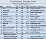
A great deal has been written of late about the demise of Moore’s Law.  The increase in field-effect transistor density with successive process nodes has slowed from the 2X every 2 1/2 years pace of earlier generations.  The economic nature of Moore’s comments 50 years ago has also been scrutinized – the reduction in cost per transistor has also abated.

The traditional technology scaling model has become significantly more complex, due to the requirements for:  new lithography systems and resists;  alternative deposition and etch equipment;  the introduction of new interconnect and dielectric materials;  and, the increasingly reliance on new design-technology co-optimization (DTCO) integration methods.

Parenthetically, the emergence of various 2.5D and 3D multi-die packaging offerings has led to the use of the term “More than Moore” integration.  The potential diversity of die functionality and process selection in these packages offers additional tradeoffs in realizing effective density and cost, the foundations of Moore’s Law.

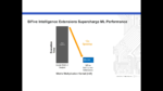
Despite all of the commentary on Moore’s Law, there remains a tremendous R&D investment on new devices that will continue to offer improved performance, power, and area.  At the recent Advanced Semiconductor Manufacturing Conference (ASMC), sponsored by SEMI, a highlight was the keynote presentation by Gary Patton, CVP & GM, Design Enablement, at Intel, who presented an overview of these R&D efforts.  His “Continuing Moore’s Law” talk offered an optimistic view on future technology features.

Gary covered the transition to gate-all-around (GAA) devices, expected to be the immediate successor to FinFETs.  (With the re-introduction of devices where the individual transistor width is again a design parameter, the transistors/mm**2 density measure will likely need a re-interpretation.)

There are numerous research initiatives underway as a potential long-term transition beyond CMOS – e.g., (arrays of) 2D semiconductor materials, such as MoS2, WS2, and WSe2.

Of particular note in Gary’s talk was the description of an area of process technology development that perhaps does not receive due consideration – the 3D monolithic integration of heterogeneous semiconductor materials, used for fabrication of optimized nFET and pFET devices.  This approach provides continued device scaling, integration of mature process fabrication techniques, and builds upon existing (CMOS-based) circuit design experience.

Before elaborating on some of the monolithic 3D possibilities, a description of the bonding of heterogeneous materials would be insightful.

Oxide Bonding and Donor Wafer Cleaving

The goal of monolithic 3D integration is to provide multiple, stacked semiconducting materials for device fabrication.  A subset of transistors is fabricated in the host wafer.  Subsequently, a donor wafer (of a different semiconductor composition) is bonded to the host, and cleaved to provide a thin material layer on top of the host for subsequent device processing.  The figures below illustrate the wafer process flow.

The full-thickness host wafer provides the mechanical support;  the thin donor layer does not add significantly to the overall thickness, enabling the use of existing process equipment and fabrication flows.  (As will be discussed shortly, there are restrictions on the thermal budget for processing the donor layer devices, so as not to adversely impact the existing host device characteristics.)

Briefly, the sequence of steps for preparation of the 3D monolithic stack is:

  • devices are fabricated on the host (300mm) wafer
  • the host wafer receives a deposition of a thin dielectric layer (e.g., chemical vapor deposition of SiN and SiO2)
  • the host wafer surface is polished (e.g., using chemical-mechanical polishing)
  • a (300mm) donor wafer is subjected to an implant of H+ (protons), using an optimized implant energy and dose
  • the donor and host wafers are bonded

Prior to bonding the host and donor wafers, specific wafer surface cleaning chemistries are employed.  It is necessary that the two wafer surfaces are hydrophilic, “atomically smooth”, and have a high density of chemical bonding sites (to preclude micro-voids forming at the interface).

In a special aligner (with dual wafer chucks), the host and donor wafers are loaded facing each other, aligned, and brought in contact.  After the initial wafer-to-wafer interface bonding has stabilized, the donor chuck is released.

Then, a thermal annealing step is applied to the composite.   This anneal performs two critical functions:  it strengthens the bonded interface, and it allows the implanted hydrogen to diffuse in the semiconductor crystal, and nucleate to form H2.  

A very thin H2 layer forms in the donor wafer, at a depth equivalent to the point of highest crystalline dislocation after the H+ implant.  This H2 layer introduces a structurally weak interface within the donor wafer crystal.

  • the donor wafer is cleaved at the internal H2 interface

A combination of mechanical edge force and/or thermal cycling results in fracturing of the donor wafer at the H2 layer depth.

  • the resulting monolithic wafer with the stacked sequence of semiconductor layers is annealed (to reduce residual implant damage), and polished

As illustrated above, the fracturing step may result in a rough surface topography, which needs to be polished before subsequent device fabrication, and layer-to-layer contact formation.

This technique for oxide bonding and donor layer transfer has been used in production for silicon-on-insulator (SOI) wafer preparation for many years.  (A deeper understanding of the mechanics behind H+ diffusion, H2 layer formation, and the structural impact on the donor wafer crystal during the nucleation annealing step remains an active area of research.)

Gary’s presentation highlighted two areas where the Intel Research division is adapting this layer transfer technique to 3D monolithic integration, to further extend Moore’s Law.

nFET in Si, pFET in Ge

One of the issues faced in advanced process development is the relatively weak hole mobility in Si, especially at higher hole free carrier density and electric field.  Current process technologies incorporated compressive mechanical stress in the pFET device channel to improve the hole mobility.  More recent advances strive to utilize a stoichiometric combination of Si and Ge directly in the pFET device channel – i.e., Si(x)Ge(1-x) – to leverage the higher hole mobility in Ge.

The team at Intel Research has been pursuing 3D monolithic integration using a Ge donor layer bonded on top of the Si host wafer, as depicted below. [1]

In this case, a FinFET device structure was fabricated on the host wafer for the nFETs, while a GAA topology was used for the pFETs in the Ge donor layer.  As mentioned above, the process flow and materials selection for the nFET high-K, metal gate, source/drain doped epitaxy, and contact metal is chosen to be compatible with the subsequent thermal processing of the Ge donor layer and pFET fabrication (e.g., <600C).

After the fabrication of the GAA pFET source/drain epi, device oxide and metal gate (using a replacement gate process), and source/drain contacts, vias are formed between the two transistor layers.

Also illustrated above is an example profile of the Ge donor layer thickness across a 300mm wafer, showing excellent uniformity of the monolithic layer transfer process (<3nm variation across the entire wafer).

The figures below depict the final 3D cross-section, the (short-channel) Si nFET and Ge pFET characteristics, and the Vout versus Vin transfer characteristics of a 3D monolithic inverter logic gate (down to VCC = 0.5V).  The Ion versus Ioff curve for the Ge pFET illustrates the improved characteristics over strained Si devices.

The use of a Ge layer stacked vertically on top of a Si layer for heterogeneous integration offers a unique opportunity for CMOS logic implementations, helping to extend Moore’s Law.

Si donor wafer on GaN host

The previous section described an approach to realize improved hole mobility in Ge pFETs.  Another area where advanced process development issues have arisen is the need for high-efficiency RF-class devices, integrated with conventional CMOS logic.  The demand for 5G (and beyond) applications requires optimum device cutoff frequency (Ft) and maximum oscillation frequency (Fmax) response, for mmWave power amplifiers, with corresponding low noise characteristics for low-noise amplifiers, and with fast switching speed for RF switches.  The excellent Ioff and low Ron of the enhancement-mode GaN device is attractive for high-efficiency integrated voltage regulator designs, as well.

Gary highlighted the work done by the Intel Research team to develop monolithic heterogeneous integration of GaN devices with conventional Si CMOS circuitry. [2]

The figures below illustrate the fabrication of a variety of GaN components, fabricated in an epitaxial layer on the host wafer (a Si substrate) – e.g., enhancement-mode and depletion-mode nFETs, Schottky gate FETs, and Schottky diodes (without the high-k gate oxide dielectric).  A cross-section of the final structured is also shown.

In this case, the donor wafer is Si, used for fabricating nFET and pFET devices, as would be used for analog functions, digital signal processing, and logic/memory.  (P-channel GaN devices are extremely challenging to fabricate.)

Whereas the circuit-level CMOS integration of the previous Si nFET and Ge pFET monolithic integration necessitates consistent (and aggressive) design rules, the distinct applications for the (RF) GaN devices and (CMOS) Si devices decouples the two technologies.  The GaN devices can be much different in dimension than the FETs – e.g., W > 10um for very low Ron – or with much longer channel lengths supporting high-voltage applications, compared to the Si FinFETs.

As with the host Si nFETs fabricated prior to bonding the donor Ge pFET layer, the GaN devices much tolerate the thermal budget of the subsequent donor Si layer transfer and nFET/pFET device fabrication.

Representative Ids versus Vg curves for the (long-channel) GaN enhancement-mode and depletion-mode nFET devices are shown below, along with the Si nFET and Si pFET device characteristics fabricated in the donor layer.

Summary

The next evolution in Moore’s Law from FinFET devices will be GAA topologies.  The opportunity to continue Moore’s Law may indeed be facilitated by 3D monolithic integration, extending the bonded layer transfer technology used for SOI wafer fabrication to a wider variety of semiconducting materials, such as Ge and GaN.  This will help alleviate the risks associated with the introduction of “beyond CMOS” materials processing.

It will be extremely interesting to track the progress and innovations in vertical stacking of devices of various types, for applications ranging from high-performance computation to high-frequency RF signal processing.

Epilogue

A passing comment at the ASMC from a member of the academic community caught my attention.   He said, “I’m seeing a diminished interest among students in pursuing microelectronics as an area of study.  They hear that ‘Moore’s Law is dead’, and conclude the field has stagnated.” 

Frankly, I cannot recall a time when there have been more opportunities for major advances in device research, processing technology, and circuit/systems applications development than at present.  If you are a student reading this article, please realize that there are many exciting careers ahead in extending Moore’s Law.

-chipguy

References

[1]  Rachmady, W., et al., “300mm Heterogeneous 3D Integration of Record Performance Layer Transfer Germanium PMOS with Silicon NMOS for Low Power High Performance Logic Applications”, IEDM, 2019, p. 29.7.1 – 29.7.4.

[2]  Then, Han Wui, et al., “GaN and Si Transistors on 300mm Si(111) enabled by 3D Monolithic Heterogeneous Integration”, 2020 VLSI Symposium, paper THL.2.


Enhancing RISC-V Vector Extensions to Accelerate Performance on ML Workloads

Enhancing RISC-V Vector Extensions to Accelerate Performance on ML Workloads
by Kalar Rajendiran on 05-17-2021 at 10:00 am

SuperCharge ML Performance

During the week of April 19th, Linley Group held its Spring Processor Conference 2021. The Linley Group has a reputation for convening excellent conferences. And this year’s spring conference was no exception. There were a number of very informative talks from various companies updating the audience on the latest research and development work that is happening in the industry. The presentations had been categorized under eight different subject matters. The subject matters were Edge AI, Embedded SoC Design, Scaling AI Training, AI SoC Design, Network Infrastructure for AI and 5G, Edge AI Software, Signal Processing and Efficient AI Inference.

Artificial Intelligence (AI) as a technology has garnered lot of attention and investment over the recent years. The conference certainly reflected that in the number of subject matter categories relating to AI. Within the broader category of AI, Edge AI was a subject matter that had an unfair share of presentations and justifiably so. Edge computing is seeing rapid growth driven by IoT, 5G and other low-latency requirement applications.

One of the presentations within the Edge AI category was titled “Enhancing RISC-V Vector Extensions to Accelerate Performance on ML Workloads.” The talk was given by Chris Lattner, President, Engineering and Product at SiFive, Inc. Chris made a strong case for why SiFive’s RISC-V vector extensions based solution is a great fit for AI driven applications. The following is my take.

Market Requirements:

As fast as the market for edge computing is growing, the performance and power requirements of these applications are also getting more and more demanding. Many of these applications are AI driven and fall into the category of machine learning (ML) workloads. And AI adoption is pushing processing requirement more toward data manipulation rather than general purpose computing. Deep learning underlies ML models and involves processing large arrays of data. With ML models fast evolving, an ideal solution would be one that optimizes for: performance, power, ease of incorporating emerging ML models and scope of resultant hardware and/or software changes.

RISC-V Vector Advantage:

The original motivation behind the initiative that have given us the RISC-V architecture is experimentation. Experimenting to develop chip designs that yield better performance in the face of expected slowdown of Moore’s law. RISC-V is built upon the idea of being able to tailor-make particular chips where you can choose which instruction set extensions you are using. Vector extensions allow for processing of vectors of any length using functions which process vectors of fixed lengths. Vector processing enables existing software to run without a recompile when hardware is upgraded in the form of more ALUs and other functional units. Significant progress has happened in terms of established hardware base and supporting ecosystem such as compiler technologies.

RISC-V can be optimized for a particular domain or application through custom extensions. As an open standard instruction set architecture, RISC-V users enjoy lot of flexibility in choosing a supplier for their chip design needs.

SiFive’s Offering:

SiFive has enhanced the RISC-V Vector advantage by adding new vector extensions for accelerating execution of many different neural network models. Refer to Figure 1 to see an example of the kind of speedup that can be gained using SiFive’s add-on extensions compared to using just the base vector extensions of RISC-V. Its Intelligence X280 solution is a multi-core capable RISC-V Vector solution (hardware and software) to make it easy for its customers to implement optimized Edge AI applications. The solution can also be used to implement data center applications.

Figure 1:


SiFive Advantage:

  • SiFive’s Intelligence X280 solution fully supports TensorFlow and TensorFlow Lite open-source platforms for machine learning (Refer to Figure 2)
  • SiFive provides an easy way to migrate customer’s existing code based on other architectures to RISC-V Vector architecture. For example, SiFive can translate ARM Neon code to RISC-V V assembly code
  • SiFive allows its customers to explore adding custom extensions to their RISC-V implementations
  • SiFive through its OpenFive business unit extends custom chip implementation services to address domain-specific silicon needs


Figure 2:


Summary:

In a nutshell, SiFive customers can easily and rapidly implement their applications, whether the applications involve Edge AI workloads or traditional data center type of workloads. If interested in benefitting from SiFive’s solutions for accelerating performance of your ML workloads, I recommend you register and listen to Chris’ entire talk and then discuss with SiFive on ways to leverage their different offerings for developing your products.

Also Read:

Die-to-Die Interface PHY and Controller Subsystem for Next Generation Chiplets

Enabling Edge AI Vision with RISC-V and a Silicon Platform

WEBINAR: Differentiated Edge AI with OpenFive and CEVA