One meaning of the word “reckoning” says it is the action or process of calculating or estimating something. But dead reckoning? What does that mean? Believe it or not, we have all deployed dead reckoning to varying degrees of success on different occasions. As an example, when driving on a multi-lane winding highway and direct sunlight hits our eyes. Although we lose visibility momentarily, we still navigate our vehicle without hitting the median barrier or another vehicle. Of course, if we had been distracted and intermittently ignoring visual cues of the surroundings, the result may have been different. As per Wikipedia: “In navigation, dead reckoning is the process of calculating current position of some moving object by using a previously determined position, or fix, and then incorporating estimations of speed, heading direction, and course over elapsed time.”
Prior to modern day navigation technologies, dead reckoning technique was used for navigation at sea. Can this technique still be useful? The answer is yes, as we saw with the highway example. How about in the technology world? How much useful can this technique be?
Last month, CEVA unveiled MotionEngine™ Scout, a highly-accurate dead reckoning software solution for navigating Indoor Autonomous Robots. And on April 27th, they hosted a webinar titled “Spot-On Dead Reckoning for Indoor Autonomous Robots” to provide deeper insights into that solution. The main presenters were Doug Carlson, Senior Algorithms Engineer, Sensor Fusion Business Unit of CEVA and Charles Chong, Director of Strategic Marketing, PixArt Imaging. Even with multiple sensors’ feeding position, orientation and speed data to the navigation system, trajectory error can start building up as sensors’ data could be momentarily interrupted or corrupted. Doug and Charles explain how CEVA’s solution helps reduce the trajectory error by a factor of up to 5x in challenging surface scenarios.
The following are some excerpts based on what I gathered by listening to the webinar.
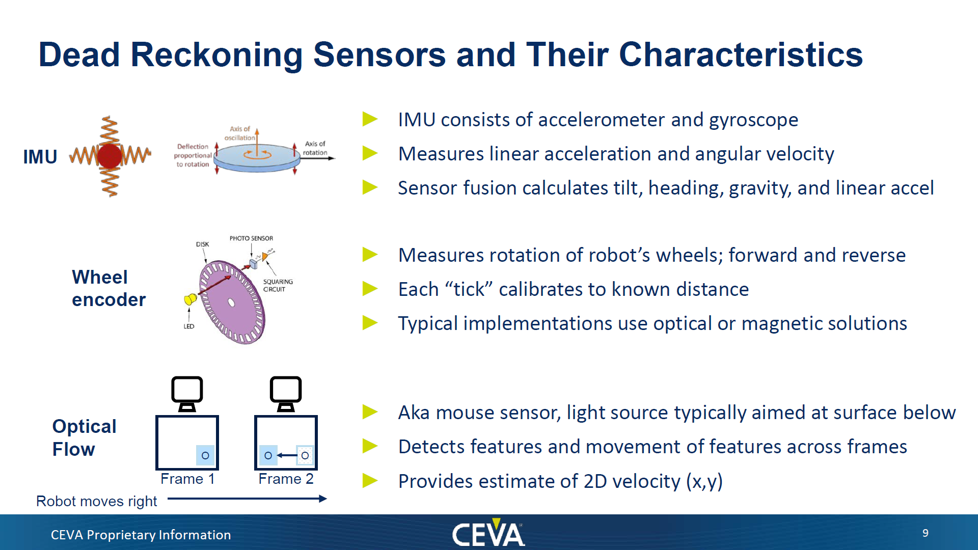
MotionEngine Scout avoids expensive camera and LiDAR technology-based sensors. Instead, it uses optical flow (OF) sensors. Figure below shows the three different types of sensors that the solution uses, how the sensors are used and what type of data they provide.

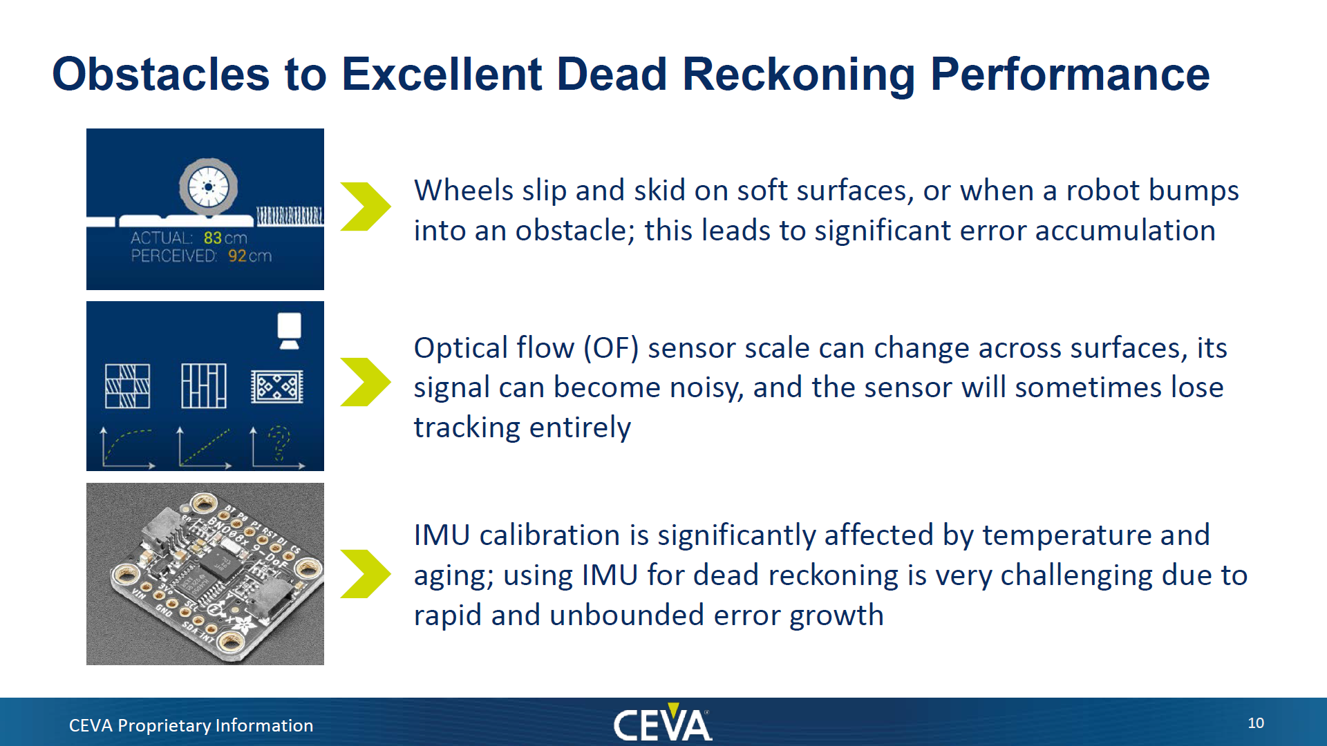
For optical flow sensing, CEVA’s solution uses PixArt’s optical track sensor, part number PAA5101. PAA5101 is a dual-light LASER/LED hybrid optical technology implementation. This approach yields best results over a wide range of surfaces. LED performs better on carpets and LASER works better on hard surfaces. Nonetheless all three types of sensors can be severely impacted by the environment and thus introduce errors in measurement data. That directly impacts dead reckoning calculations. Refer to Figure below for details on obstacles to accurate dead reckoning performance.

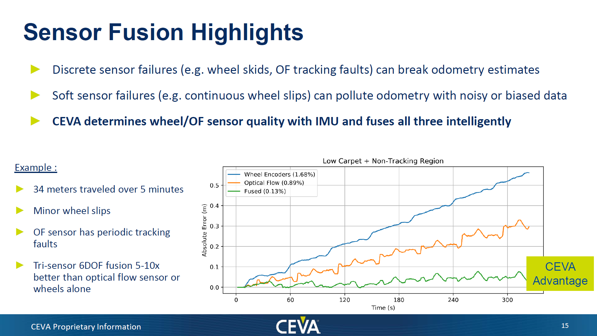
CEVA’s solution fuses measurements from these three sensors to achieve significantly better accuracy and robustness. Sensor fusion is the process of combining sensory data from multiple types of sensing sources in a way that produces a more accurate result than is possible with just the individual sensors’ data. MotionEngine Scout leverages 15+ years of CEVA R&D in sensor calibration and fusion. The solution is able to minimize absolute error by a factor of 5-10x over relying on just wheel encoder or optical flow sensor data. Refer to Figure below.

MotionEngine Scout is the software package that is being released to address the indoor autonomous robot market. It can support residential, commercial and industrial settings. Evaluation hardware will become available to customers in May/June 2021. The hardware will be in the form of a single PCB module and simple to integrate with customer’s robot platform.
As a backgrounder, MotionEngine™ is CEVA’s core sensor processing software system. More than 200 million products leveraging MotionEngine system have been shipped by leading consumer electronics companies into various markets. Check here for a list of MotionEngine based software packages supporting different market segments.
For all the details from the webinar, I recommend you register and listen to it in its entirety.
If you are developing indoor autonomous robots, you may want to have deeper discussions with CEVA. Their software package may help you address the challenging pricing requirements of your market.
Also Read:
IP and Software Speeds up TWS Earbud SoC Development
Expanding Role of Sensors Drives Sensor Fusion
Sensor Fusion Brings Earbuds into the Modern Age
Share this post via:


Comments
There are no comments yet.
You must register or log in to view/post comments.