
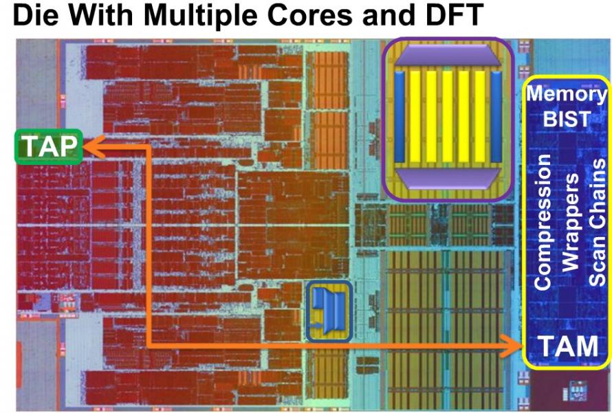
IC designers have been creating with hierarchy for years to better manage large design sizes, however for the test world the concept of hierarchy and emerging standards is a bit newer. TSMC and Synopsys jointly created a webinarthat addresses hierarchical test, so I’ve attended it this week and summarized my findings here. Adam Cron, SynopsysThe first presenter was Adam Cron from Synopsys and he showed how a typical SoC today has:
- Multiple cores
- IP blocks
- DFT components
- Scan Chains (yellow color)
- Wrappers (blue color)
- Compression (purple color)
- Memory BIST
- Test Access Port (TAP)
 The TAP is well defined by the IEEE standard 1149.1To place a core on an SoC and make it compliant with the IEEE standard 1500for hierarchy is well documented, and this standard was approved back in 2005. Synopsys has a test tool called DFTMAX that will:
- Create the hierarchical test models
- Provide scan synthesis
- Add wrappers for compression
These core test models (CTL) comply to the IEEE standard 1450.6 and this successful standard:
- Supports hierarchical DFT synthesis
- Maps pattern data to the Test Access Mechanism (TAP)
- Supports protocol porting
In a Synopsys tool flow here’s how these CTL models get assembled into a full SoC hierarchy: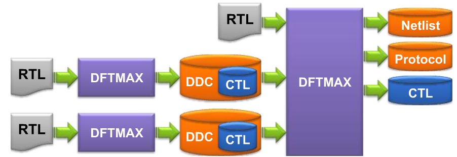 CTL is powerful enough to describe all DFT approaches like: Parallel scan chains, compression, multiple protocols, etc.The STILstandards (1450.0 and 1450.1) define test data patterns, while CTL defines the test protocols.Core WrappingTo really make test hierarchy work you have to wrap each core in a standardized way. The IEEE standard 1500 defines core wrapping which includes support of your hardware using CTL and test patterns with STIL.DFTMAX will automatically create our IEEE std 1500 hardware as shown below where the core being wrapped is at the top.
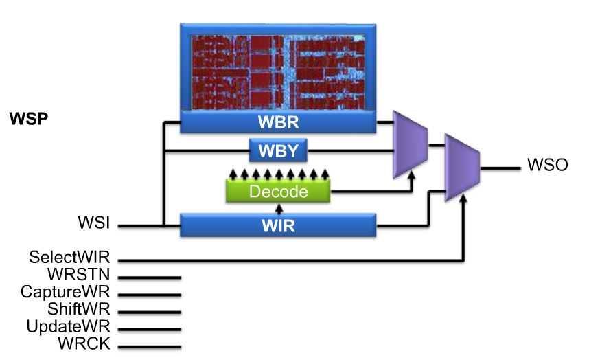 Once you’ve wrapped all of your cores and major IP blocks, the next step is to integrate all of these at the top-level of your SoC.
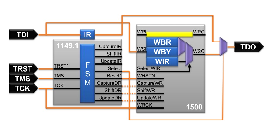 This diagram shows only one wrapped block, however in a real SoC you would have dozens of blocks wrapped with 1500 test hardware.
 Presenting next was Dr. Saman Adham, a senior manager at TSMC with 23 years of experience in Design For Test (DFT) and he talked about the motivation of using IEEE std 1500. From a foundry viewpoint TSMC has certain IP design and test constraints:
- IP data security
- High coverage for internal IP tests
- High coverage of IP during external testing
- Minimizing the area and performance overhead of test structures
- Automation of wrappers and model generation
With IEEE std 1500 you can test cores individually, or in parallel as shown below where two cores have been wrapped.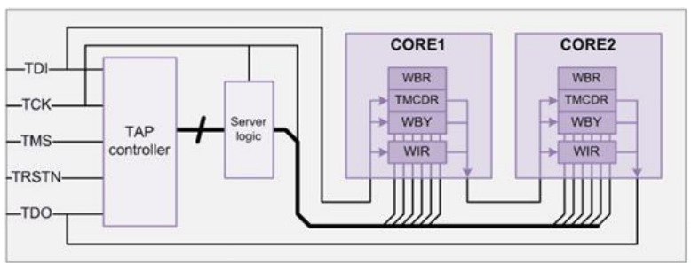 A shell model is used to protect the details of an IP block and yet still work with std 1500.
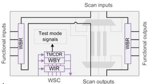 More Efficient WrappingAdam came back and shared how to minimize the test overhead of wrapping by using shared wrapper cells instead of dedicated wrapper cells.iJTAGThe IEEE standard P1687 (Proposal stage) is used to describe access and control of on-chip instruments using a laptop connected to a system with JTAG using ICL to describe hardware and PDL to describe tests:
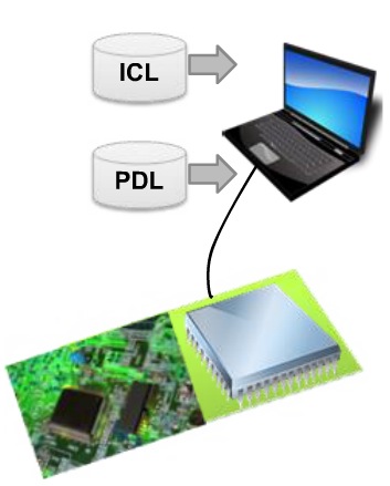 An example use of P1687 is to read out the values of an on-chip temperature sensor. There are similarities in signaling used by both IEEE std 1500 and P1687:
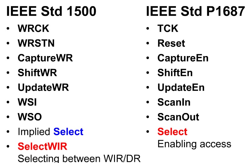 Look forward for EDA support of P1687 as it moves from the proposal to adopted stages.Q&AQ: Can DFTMAX 1500 wrappers do slack-based transition-fault testing, core to core, die to die for a 3D stack? A: Yes, 3D and TSV are good applications.Q: Is P1687 also iJTAG?A: Yes, it is.Q: Is 1500 really a standard?A: At first it was called P1500 during the proposal phase, while 1500 has been standardized for 7 years.Q: Can I define how many scan chains are in each mode of the blocks.A: Yes, see the training videos on SolvNet for details.Q: Can I tell the tools what clocks to use for dedicated wrapper cells?A: It will automatically find the clock, or you can define the clock, see SolvNet.Q: Once I generate iJTAG files, what comes next?A: PDL and ICL files will be read by DFT tools in the future.Q: Where are the documentation on 1500 wrapping?A: Ask your account team for this.Q: Are you compatible with 1500 that I manually create?A: Yes, we just need the CTL models.Q: What does it mean for 1149.1 to support 1500?A: The block level from 1500 is supported by 1149.1.Q: Which test port should I use?A: Use the 1149.1 for chip-level test access port.Q: What is the area overhead for 1500?A: For just wrapping it’s small, so it’s mostly the area of the wrapper cells.
Further StudyThe complete 40 minute webinar is available online here.
lang: en_US


Comments
There are no comments yet.
You must register or log in to view/post comments.