With advancement of semiconductor technologies, ever increasing sizes of SoCs bank on higher densities of design rather than giving any leeway towards increasing chip area and package sizes; a phenomenon often overlooked. The result is – larger designs with lesser number of pins bonded out of ever shrinking package sizes; the design size per pin count keeps increasing. This is a challenge, test engineers take silently, but how to keep the test cost down without diluting the test reliability? The test vectors to test the increased functionality on chip will increase and not decrease. So, smart techniques are needed in test engineering too to test larger designs with same or lesser number of pins at the same or lesser cost of testing.
Reducing ATPG patterns test time and test data volume, which can be achieved by scan test compression specific DFT (Design for Testability) architecture, can significantly contain the overall test cost. The compression structure which uses a broadcast/XOR network of scan-input pins, XOR/MISR (Multi Input Shift Register) logic on the scan-output pins and a number of scan channels (stumps) connected to compression logic. When the scan chains are properly balanced then they can provide test time and test data volume reduction close to the target compression ratio (i.e. the ratio of number of scan channels to the external full-scan chains). A compression efficiency of 100-200X has been observed provided the scan data pin pairs remain high. The moment scan data pin pairs are reduced to five or lesser, the compression efficiency and fault coverage go down drastically; at the scan input data correlation increases and at the scan output data aliasing increases, resulting into failures being masked out, thus affecting the reliability of test. So, what’s the alternative given that LPCT (Low Pin Count Test) designs are the way of life in the SoC world of testing?
I was pleased to know about Cadence’sEncounter Test SmartScan technology that offers a robust, highly efficient and reliable scan compression solution for LPCT designs.

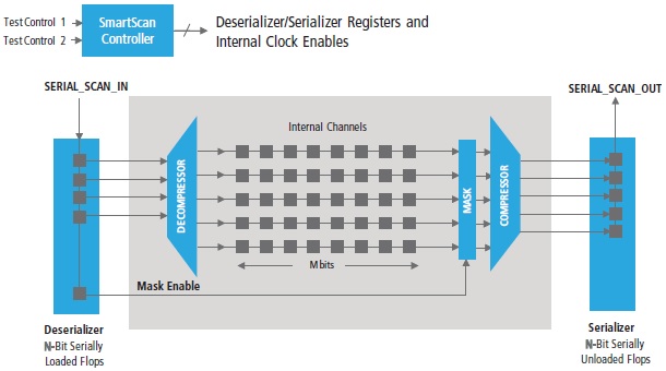
It utilizes two N-Bit shift registers for de-serializing and serializing the compressed data, thus requiring a single pair of scan-in and scan-out pins. After fully loading the input shift register with the compressed data (which takes N cycles for a single bit-slice of the scan channels), the scan clocks are fired and data is transferred into the internal scan channels. The output shift register captures the response data in parallel from the internal scan channels and shifts it out serially.

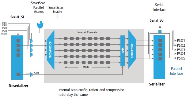
The test patterns are generated using N-bit parallel scan interface by bypassing the de/serializer registers. These patterns are re-targeted to the Encounter Test SmartScan serial interface by translating each scan cycle of the parallel interface pattern into loading and unloading the de/serializer registers. The parallel interface pattern can also be directly applied at the automated test equipment (ATE) provided the chip package has those pins for test purposes. The test control signals required to switch between parallel and serial interfaces can be internally decoded from on-chip test logic.
This arrangement reduces scan data correlation to large extent which is not possible with only a few pins driving the compression logic directly. The pattern quality is consistent requiring a single-pass ATPG run, because the internal scan configuration is identical between the serial and parallel interfaces. Debugging and diagnosis is easy to isolate tester failures.
The Encounter Test SmartScan logic is verified in the context of post-ATPG pattern retargeting which avoids any re-iteration of DFT verification and ATPG flows (due to any error in its implementation) which could be expensive.

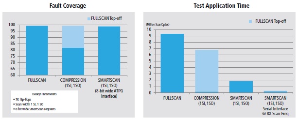
Above are the results of fault coverage and test time on an automotive design. It can be clearly seen that SmartScan methodology provides quality close to full-scan (i.e. with single scan chain) at a much lower test time compared to full-scan. The quality of conventional XOR compression is drastically lower and unreliable.
The Encounter RC cockpit provides a seamless environment for insertion of SmartScan logic into the front-end design netlist. A single logic-synthesis and DFT-insertion run script is used to achieve the best area, power, timing, and test coverage. The RTL Compiler also generates all downstream run scripts to verify design equivalence with Cadence Conformal LEC, generate parallel interface patterns and retarget them for Encounter Test SmartScan interface, and provide fault coverage metrics with Encounter Test True-Time ATPG.
The Encounter Test SmartScan methodology provides the much needed solution for LPCT designs in automotive, MCU and mixed-signal applications at significantly reduced test cost and high quality of test and fault coverage. A further detailed description can be obtained from a whitepaperwritten by Pradeep Nagaraj at Cadence.
More Articles by Pawan Fangaria…..
Share this post via:


Comments
There are no comments yet.
You must register or log in to view/post comments.