In 2014, many of the customers that my team and I supported in North America were still using HFSS 3D to model boards and packages. These customers were content with that interface, able to get their models setup quickly, and were okay with the solution times because when HFSS gave them an answer, they knew it was the right answer. I was a little frustrated with this situation because Ansys had delivered some amazing technology in the HFSS 3D Layout environment, and within the HFSS solver, to allow customers to get to those extremely accurate answers, but in less time. As I have blogged about before, Ansys introduced key technologies that enabled substantial reduction in simulation times:
- Phi Mesher – efficient meshing technique that tackles layers structures found in PCB, package and IC designs
- Distributed Direct Solver – distributes the matrix solution during the adaptive pass or frequency sweep stages across multiple cores or across multiple nodes for improved scalability
- Auto HPC – allows HFSS to optimally apply the total number of cores and/or machines available to solve the project in the most efficient manner
- Ansys on the Azure Cloud – made HPC extremely easy to access and to scale up cores/RAM to solve models fast
These were just a few of the key advances in the software that allowed users to speed up their simulations time… yet users were not switching to HFSS 3D Layout. 6 years later, in June of 2020, due to competitive claims to HFSS, our customers came to us stating, “I hear that other tools can run faster than HFSS… how can you make HFSS run faster?” Like a broken record I told them about HFSS 3D Layout, the Phi Mesher, Distributed Direct Solver, Auto HPC, and Ansys on the Azure Cloud. Those competitive claims was just what we needed to get our customers to see the light! HFSS 3D Layout was poised to be the solution that they were looking for, and for every benchmark ran, it reduced their solutions times from 2X to 20X in some cases. 18 months later, our customers have fully embraced HFSS 3D Layout for their chip/package/board workflows, and I see they are benefiting in 2 ways… some are able to solve their critical nets way faster than before, and are able to give pass/fail metrics to their designs teams a lot sooner. This allows these teams to get their products to the market faster. The other benefit I see is that customers are solving 2X to 4X the amount of nets that they would have solved before. The simulations times are still reasonable for the increased amount of nets, and customers are able to characterize reliability concerns like cross-talk and cross-coupling to ensure robust designs. Being able to solve larger portions of the designs in one model allows customers to reduce failures after production because they have modeled more of the design under real-world conditions.
With the incredible success our customers have had with HFSS 3D Layout, there is still one issue that I see still today with their models… and that is ‘cutouts’. Customers are still trying to make the model as small as possible to reduce the amount of RAM it needs to solve. I want to stop this practice, but I know it is engrained in our user base… and I know why they do it… ME! Yes, this was a common practice 5-10 years ago when the overwhelming majority of our customers were running projects on one machine. This machine may have had 250GB if they were lucky, and making sure the simulation was able to mesh, adaptively refine and complete a frequency sweep, all within that RAM footprint, was critical. So Ansys’ AE staff back then would teach customers how to create cutouts that would minimize size of the model, and in turn, minimize the RAM footprint. Sometimes that practice would cause accuracy issues because the cutout would be too close to the traces and adversely effect the return path, and/or introduce false return paths. There were 2 common ways to cut the model: using a conformal cut that followed the path of the traces (which often caused rounded edges) or manually creating a polygon to closely follow the traces. We would also teach customers to methodically go through the design and remove any object that was not electrically important to the model, Objects like vias, pads, and thru-holes were all manually removed to get rid of those unnecessary mesh elements. This type of cleanup could take hours to perform.
So, I am happy to announce that with 2021R2 HFSS 3D Layout, with the before mentioned key advancements in the software, we can abandon those practices. Our suggestion is to just use a rectangular cut well enough away from the traces. No more conformal cuts, no more polygons, and in general… no need to perform excessive cleanup. Why should you use just a rectangular cutout? For one, hardware has dramatically improved. Many customers have access to on-prem hardware that is well above the previous standard of 250GB of RAM. They have been able to string multiple machines together to allow larger simulations to run without issue. We have also seen adoption of the Ansys Cloud which has given customers access to cores/RAM needed to solve their biggest projects. Secondly, rectangular cuts tend to help the mesher reduce unnecessary edges and vertices that were introduced in the old cutout methodologies.
Need more convincing? Below, I show a quick comparison of the old methodologies used for cutting out a model, versus the 2021R2 methodology of using a rectangular cut.
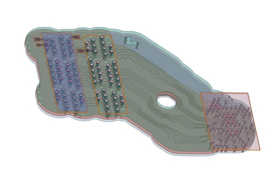
- The Conformal Cutout – The outer airbox follows the path of the traces which creates many rounded edges and vertices
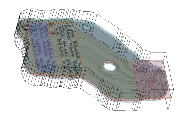
- The Bounding Box – Uses a polygon to cut through the model, but causes excessive dielectric regions which didn’t match with the real-world operation
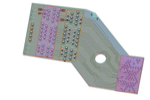
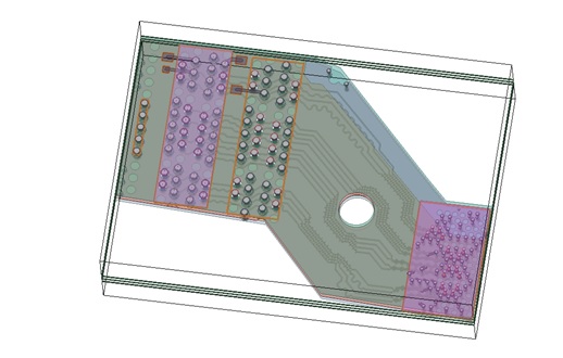
- The Rectangular Cut – The outline is far away from the traces, and ensures the natural return path is preserved
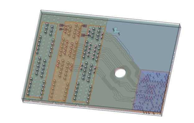

Key takeaways from the simulation results
- Creating the smaller models didn’t solve faster
- Conformal – 54mins; Bounding_Box – 52mins; Rectangular Cutout – 47mins
- The total solution time for the adaptive convergence was fastest with the rectangular cutout. This largely has to do with the convergence taking only 9 passes rather than 10.
- The smaller models had less initial/final mesh elements
- This is true, but I wanted to show that a larger cut doesn’t mean that it will take longer to solve. As you can see, the rectangular cut produced the smallest RAM footprint. The rectangular cut allows the mesher to focus the mesh refinement on fields around the traces, and not on the edge boundary conditions.
- Conformal – 79GB; Bounding_Box –66GB; Rectangular Cutout – 63.3GB
- Take the guess work out of the simulation
- Making a large rectangular cutout allows the users to avoid making cutouts to small that may affect the return paths.
- It reduces the need to clean up the model
Summary
- Use the latest release, which is currently 2021R2
- Use HFSS 3D Layout for planar designs like IC, packages, and boards
- Use rectangular cutouts when cutting models down from their original size
- Contact an Ansys AE if you need help with setting up any of our models!
& cut out the cut outs!
Also Read
Is Ansys Reviving the Collaborative Business Model in EDA?
A Practical Approach to Better Thermal Analysis for Chip and Package
Ansys CEO Ajei Gopal’s Keynote on 3D-IC at Samsung SAFE Forum
Share this post via:


Comments
There are no comments yet.
You must register or log in to view/post comments.