I would contend there is no job quite like working as a support engineer for a simulation tool like Ansys HFSS. Such a role forces an engineer to understand technology in breadth and depth like no other because HFSS is applied to such a broad range of applications and products throughout the world. My own introduction to HFSS began in 1999 at a small antenna startup in California where it quickly became an invaluable tool in our design flow. One of HFSS’s best features is the ability to visualize electromagnetic fields. The first antenna I simulated with HFSS was an inverted-F antenna for GSM and the first post-processing operation was an animated plot of the wave propagating from the antenna like the image below.
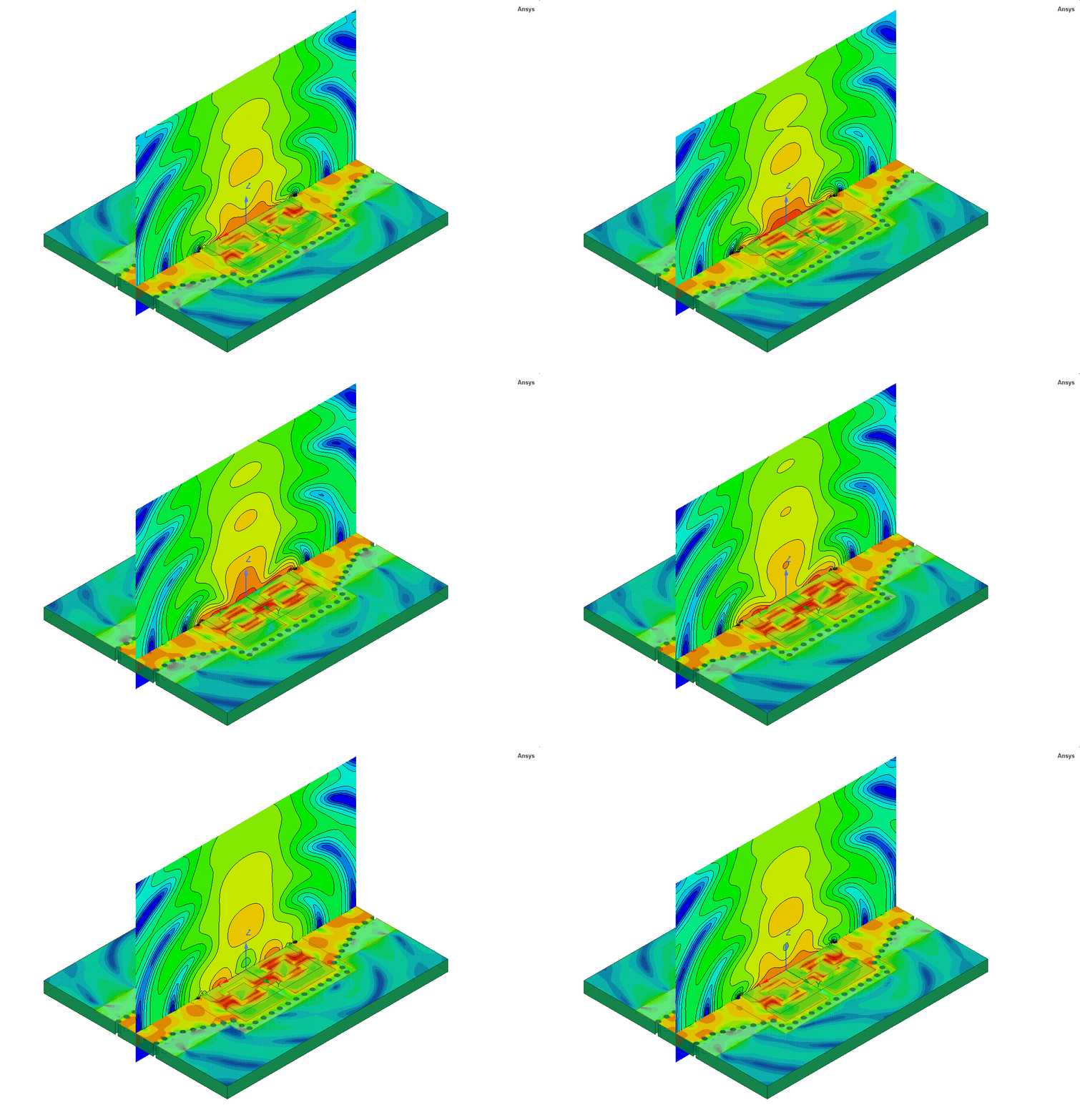
The insight into the antenna behavior provided by this field animation was impossible to obtain in the lab. I was truly excited to have a job where I used HFSS daily to design and optimize electromagnetic antennas and components. It was fun, and several months later I joined Ansoft as an HFSS support engineer. In the new role, I suddenly had to wear many hats and learn many new technologies and applications. For example, when supporting engineers working on signal integrity, a new topic for me at the time, I remember asking my colleagues questions like “What’s a net?” and “Why do they call holes in ground planes anti-pads?” I had a lot to learn. After years of helping many users successfully leverage HFSS to solve their toughest design challenges, I developed an appreciation of the power of HFSS and established a few “HFSS axioms”.
One axiom is the hubristically sounding “When you and HFSS disagree, assume you are wrong.” And while I am not trying to say “HFSS is always right” (although you will hear me state that as well), what I am saying is, given the deep “Maxwellian knowledge” imparted to HFSS by its developers, I advise approaching the “disagreement” as an opportunity to learn from HFSS rather than assuming HFSS is at fault. I learned this lesson the hard way, repeatedly. For example, when the impedance of a “50 Ohm” microstrip trace was “blowing up” near DC and I raised a question, a disappointed HFSS developer pointed me to the phenomenon of the RC transmission line effect.
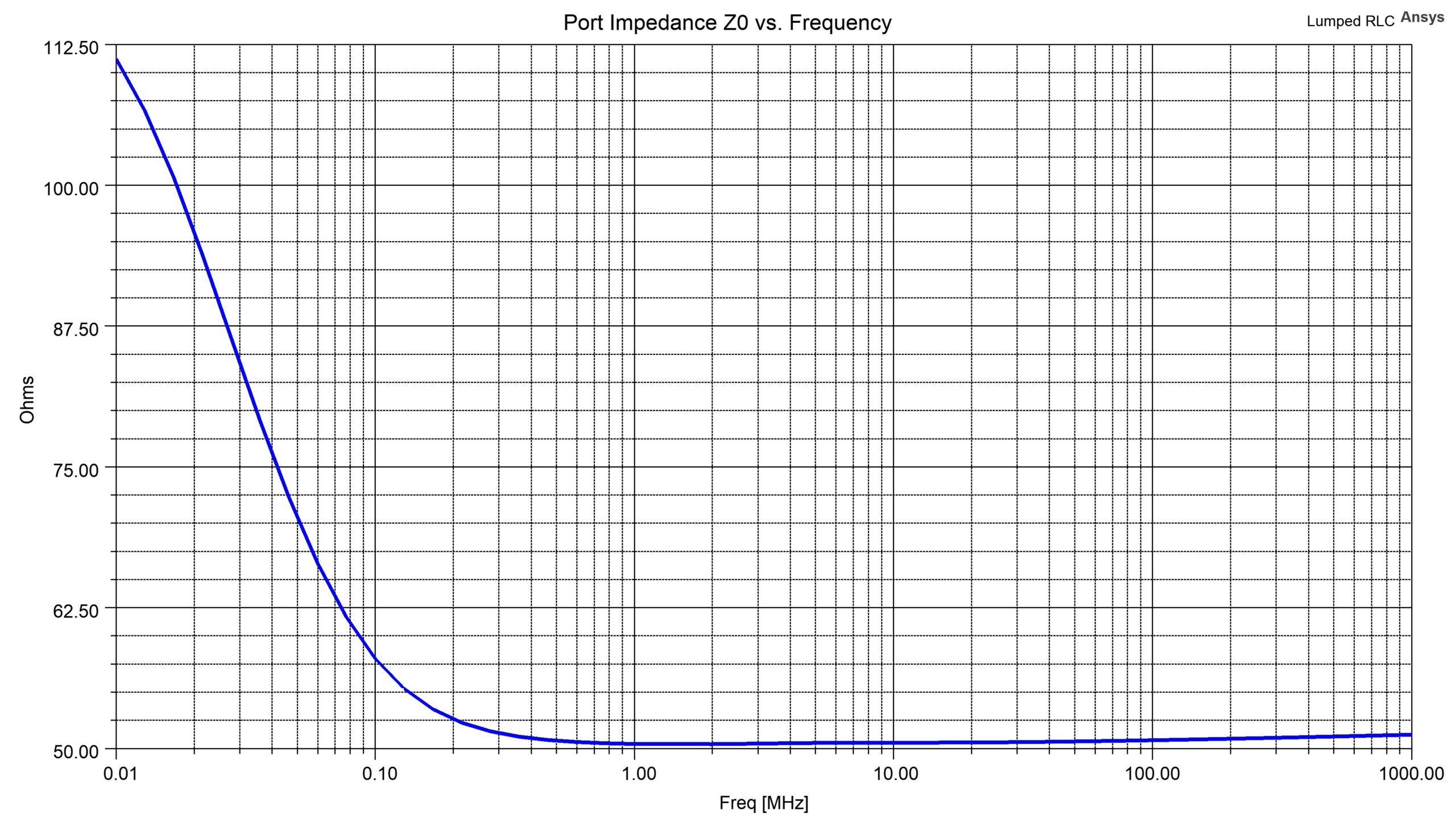
By the way, this prediction of the RC transmission line behavior is correctly predicted by a possibly underappreciated capability of HFSS: its waveport technology.
Another sometimes point of “disagreement” between HFSS and users relates to the terminals of an S-parameter model when used in a circuit schematic. The discussion usually revolves around simulating printed circuit boards (PCBs) and how to connect a surface mount device (SMD) such as a chip capacitor as part of a larger system when HFSS is used to extract a model of the PCB’s footprint (Fig. 3).

This model is comprised of three conductors. The top two are trace_ left, and trace_right and the conductor on the bottom of the PCB is called ground. Ports are at the outside ends of the two traces. Here the chip capacitor could be modeled as an HFSS 3D Component. However, a simplified approach would be to approximate the capacitor with a lumped RLC boundary condition (BC). But, what if the value of the chip capacitor needs to be changed? Instead of re-solving the full HFSS design for each capacitance value, the chip capacitor could instead be modeled with two ports, one on either pad referenced to the object named ground (Fig. 4). The resulting four-port model can be placed in a circuit schematic and the capacitor can be connected between the two new terminals. When the circuit analysis is performed the results returned are the expected response of a series capacitor (Fig. 5). Now if the capacitance value needs to be varied it is not necessary to rerun an entire HFSS simulation but only to run a new circuit analysis with the new capacitor value.
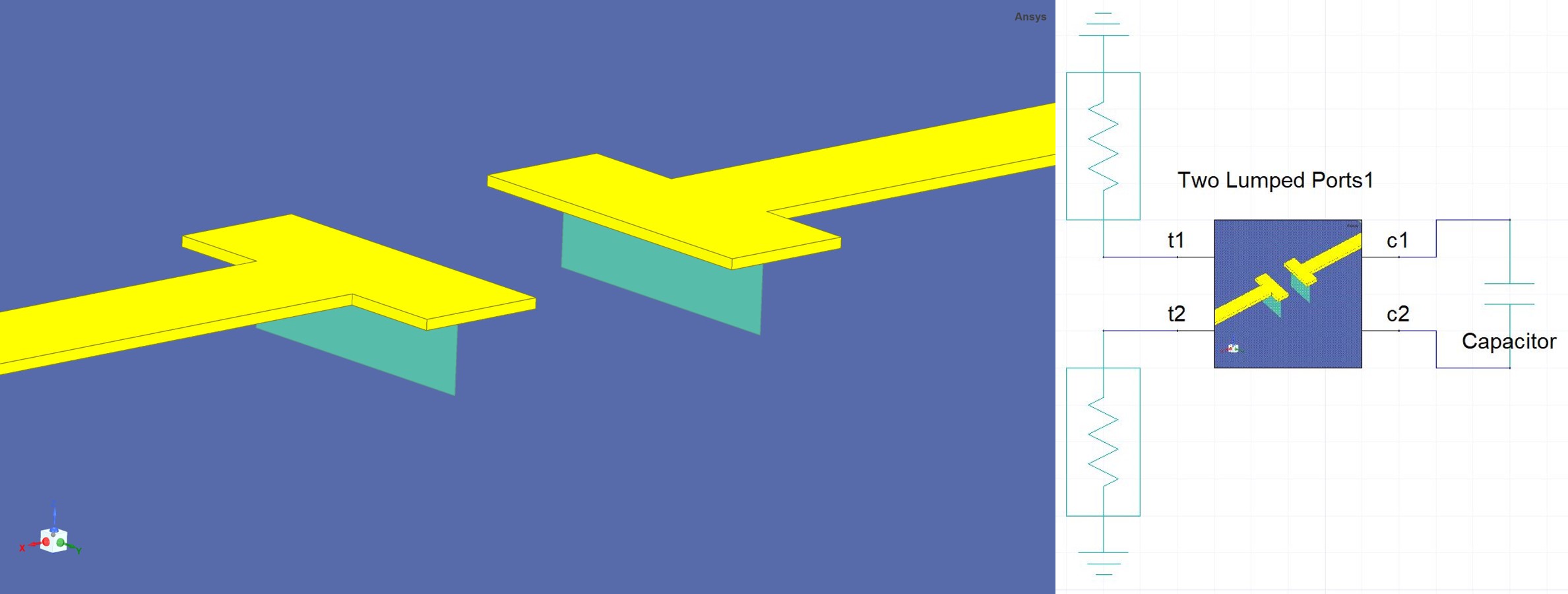
Fig. 4: Two lumped port HFSS series capacitor model (left) and the circuit schematic (right)
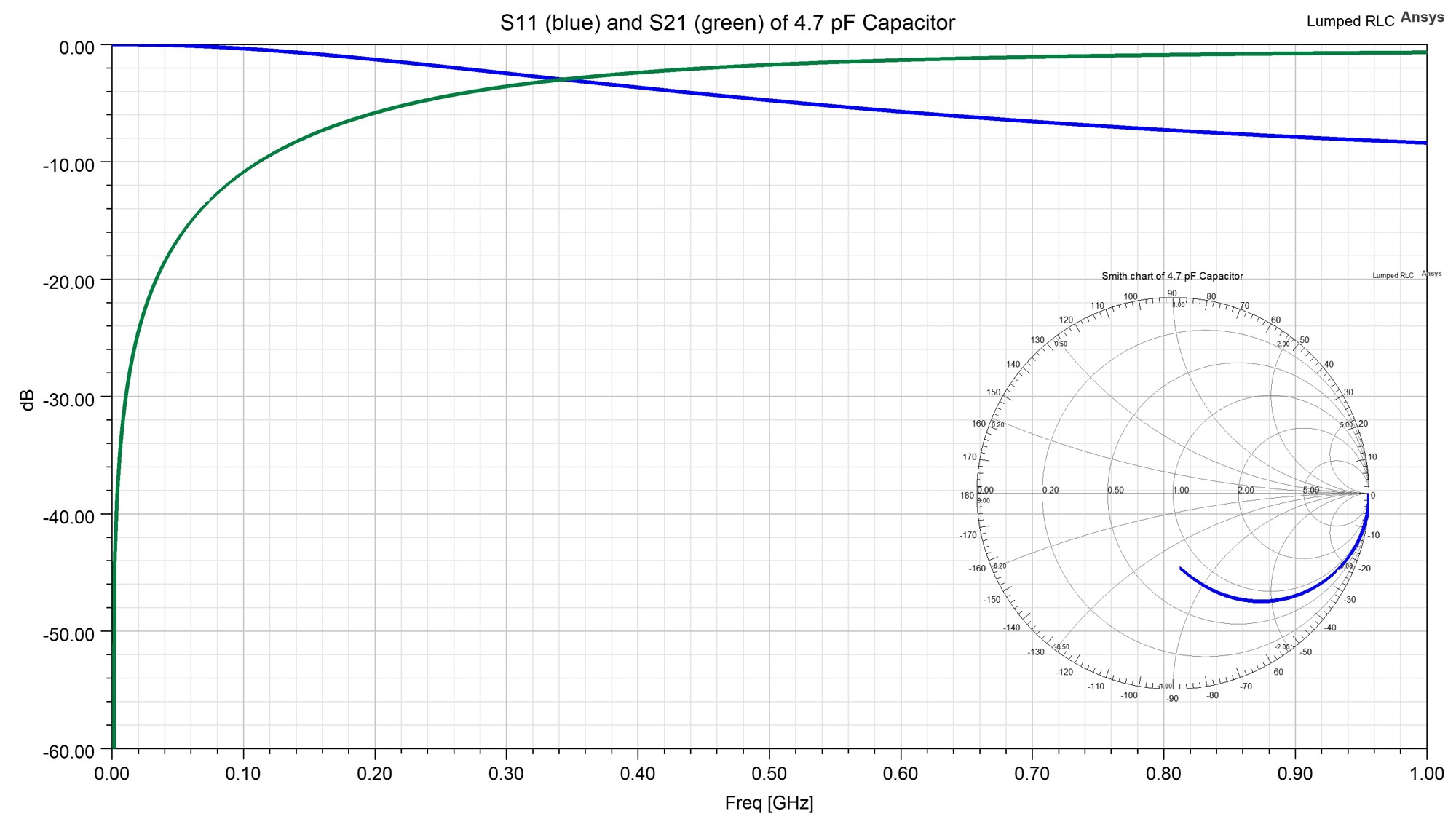
Fig. 5: S-parameters of series 4.7pF capacitor modeled on substrate in Fig. 4
This is straightforward but it turns out there is a simpler way to use only a single port to represent the capacitor. A key to understanding this is to recognize that the ground symbol in the circuit schematic is not the same as the conductor named ground in the design. So here instead of two lumped ports, all that is needed is a single lumped port across the gap exactly where the series lump RLC BC of Fig. 3 is located. Then, somewhat unintuitively, in the circuit schematic, the same capacitor model is connected from the terminal of the one port to the ground symbol (Fig. 6).
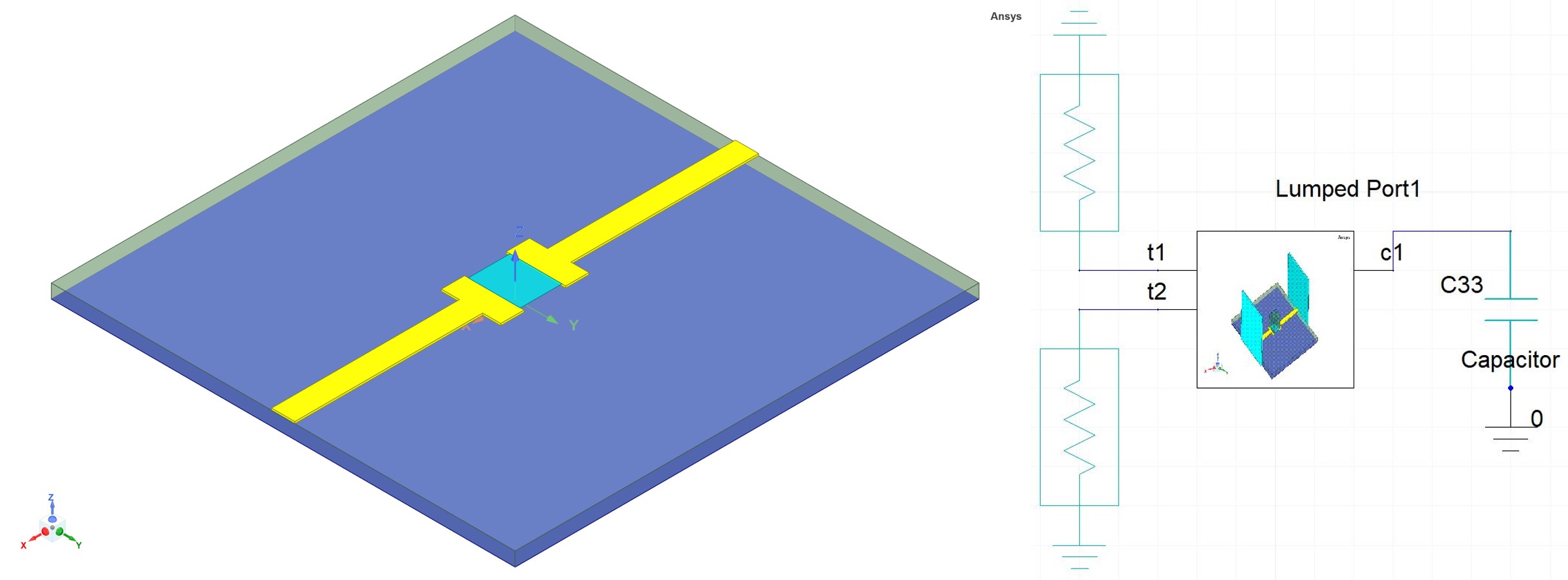
Fig. 6: Lumped RLC BC replaced with lumped port (left) and the circuit schematic (right)
Now run the circuit simulation and compare the results with the lumped RLC BC design and the results lie on top of one another (Fig. 7). Here the capacitance is plotted, calculated from the Y-parameters.
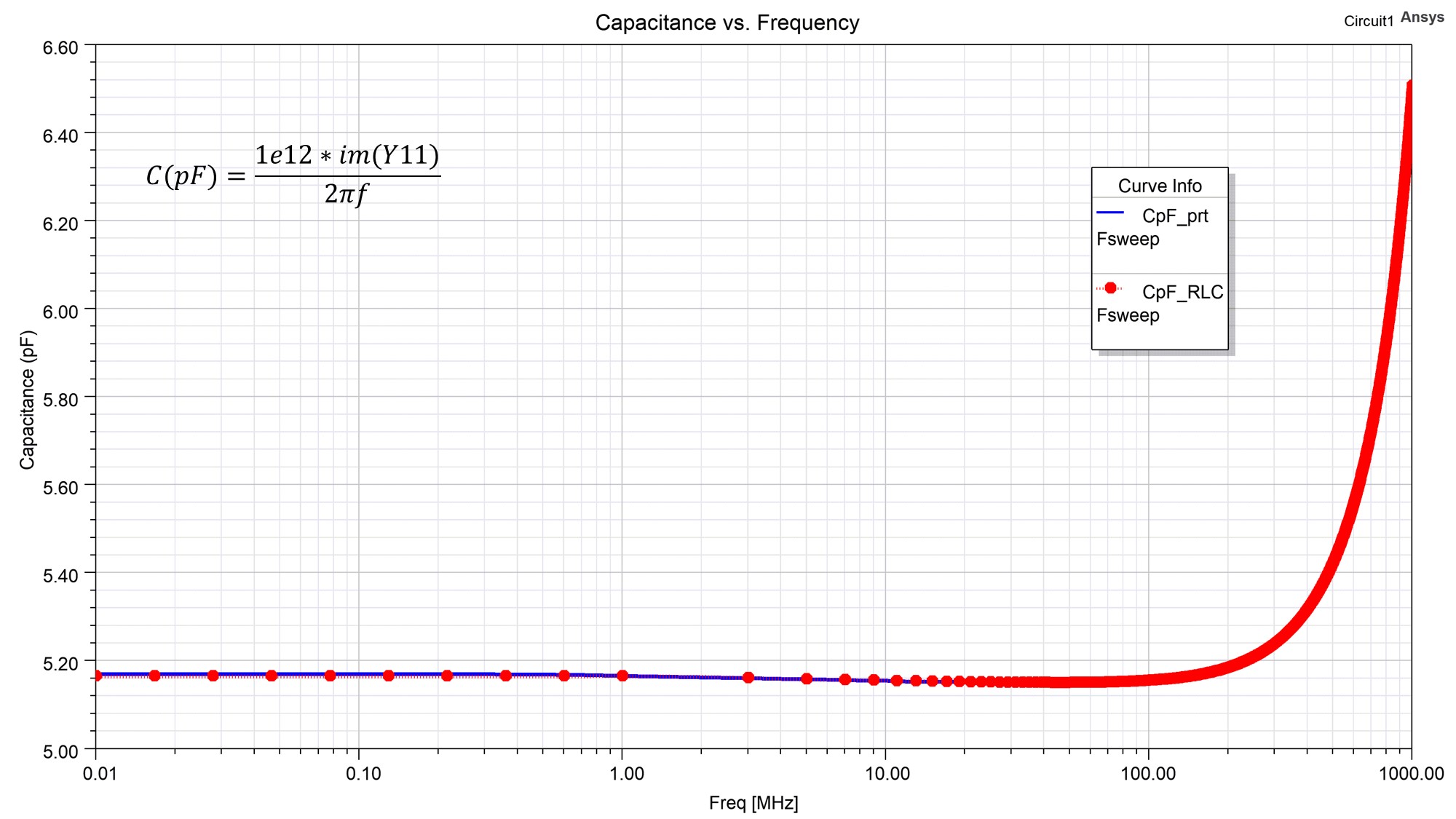
Fig. 7: Capacitance vs. frequency. Lumped RLC (red) vs. lumped port (blue)
Why is this? Well, first it helps to recognize that the terminals of an S-parameter model do not represent where a current enters a conductor but instead represent the location at which an electromagnetic wave enters a waveguide, in this case, the microstrip waveguide. This waveguide is composed of the microstrip traces, the dielectrics of the substrate and air above, and the conductor arbitrarily called “ground” on the bottom. Another way to think about it is that a S-parameter model has the return path, call it “ground”, implicitly contained within it. Thus, that ground symbol on the end of the capacitor in the schematic is not the “ground” conductor of the PCB since that is already inside the S-parameter model but instead in the circuit schematic, it just closes the loop back to the same ground symbols of the circuit ports. The naming of the bottom conductor as ground in the HFSS design was completely arbitrary, it is not the same thing as the ground symbol in the schematic. It could have just as easily been named “Bob” and it would not have changed the physics of the simulation. So as in the real world, and since Ansys HFSS solves the full set of Maxwell’s Equations, another axiom arises which is There is No Such Thing as Ground. Another way to see the arbitrariness of the name ground is to note that the three conductors and three ports are connected in series, looped around a dielectric, the substrate, and surrounded by another, the air (Fig. 8). Other than their physical shapes they are completely equivalent, no one of them more appropriately called “ground” than the other.
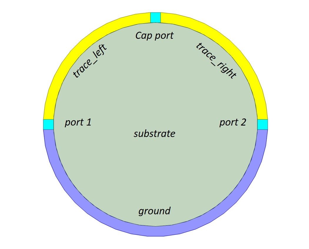
Fig. 8: Conceptually these three conductors and ports are connected in series. No conductor more “ground” than another.
So, with the above knowledge, the next time you wish to leverage an S-parameter model from HFSS in a circuit simulation, you may find it a bit easier to define (and minimize the number of) the ports needed in HFSS. Come to think of it, so I do not confuse myself in the future, from now on I may start naming those conductors “Bob”. If you are a student interested in electromagnetics and simulation and want to learn more about the fundamentals of electromagnetics follow us on Ansys Electronics on LinkedIn and look for a big announcement in the next release of HFSS.
Static gif of Fig. 1
Also Read
Bouncing off the Walls – How Real-Time Radar is Accelerating the Development of Autonomous Vehicles
The Electromagnetic Solution Buyer’s Guide
Share this post via:


Comments
There are no comments yet.
You must register or log in to view/post comments.