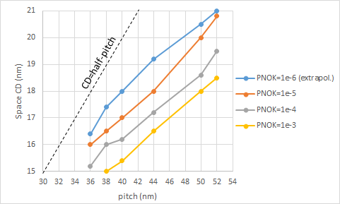
Ongoing investigations of EUV stochastics [1-3] have allowed us to map combinations of critical dimension (CD) and pitch which are expected to pose a severe risk of stochastic defects impacting the use of EUV lithography. Figure 1 shows a typical set of contours of fixed PNOK (i.e., the probability of a feature being Not OK due to a stochastic defect [1,2]) in CD-pitch space. In this case, the stochastic failure is a microbridge, i.e., a failure of a trench (space) to open up at a given location.
Figure 1. Stochastic failure (microbridge) probability contours in CD-pitch space. The dotted line represents the half-pitch limit, which has substantially lower failure probability. Based on Figure 11 in [1].
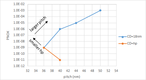
The results of Figure 1 are used to draw PNOK trends for fixed 18 nm CD in Figure 2. The half-pitch trend is also added from the same reference.
Figure 2. Stochastic failure (microbridge) probability increases for smaller half-pitch, but at fixed CD, it increases with pitch. Half-pitch trend is based on Figure 19 in [1].
A half-pitch in excess of 18 nm is needed here to guarantee PNOK less than 1e-9. The number of photons is always proportional to dose, but for features attached to dense half-pitch lines, such as line ends and contact/via hole edges, it is also proportional to pitch^2. On the other hand, for fixed CD, photon number is effectively reduced at larger pitches, because the number of separate coherent images (which are qualitatively different) increases with pitch (Figure 3). As a reminder, a lower photon number results in a larger % standard deviation, resulting in naturally randomly occurring local underexposure and overexposure at the feature edge [4]. It should be noted that Figures 1 and 2 only refer to a particular resist exposure condition with a particular dose for targeting the particular CD. A higher dose would reduce the photon shot noise but increase the number of secondary electrons and heating.
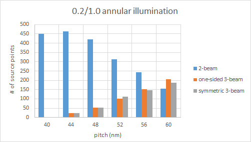
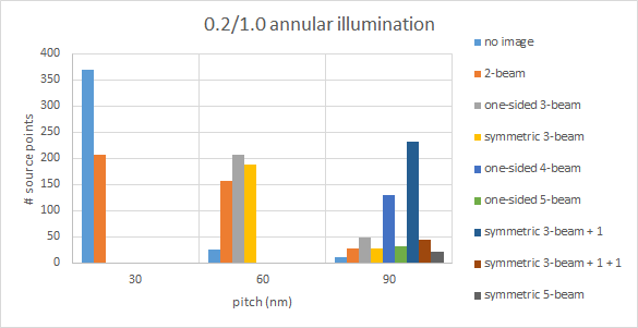
Figure 3. As pitch increases, more light is diverted from two-beam to three-beam images.
The example in Figure 3 for 0.33 NA and 0.2/1.0 annular illumination, a condition for bidirectional layouts over an extended pitch range, shows that increasing pitch toward 60 nm leads to a nearly equal 3-way splitting of the dose among three different coherently illuminated images. This is expected to aggravate the stochastic effect.
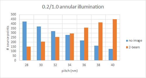
When the CD is equal to the half-pitch, the one-sided 3-beam image converges to the 2-beam image, so the 3-way dose split becomes 2-way, offering relief against the stochastic degradation. This explains why PNOK improves by CD approaching half-pitch. However, as the pitch decreases, a smaller portion of the pupil accounts for the 2-beam image, while a larger portion produces no image at all (Figure 4). This aggravates the PNOK degradation at smaller half-pitches.
Figure 4. As the pitch decreases, fewer pupil source points support two-beam imaging; instead most points provide no image at all, only background light. For a given mode of illumination, this aggravates the occurrence of stochastic failures, as the fraction of photons producing images has decreased.
The EUV mask also aggravates the stochastic issue, through the effect of shadowing. As shown in Figure 5, the 30 nm pitch is highly susceptible to the significant shadowing difference between illumination points on opposite sides of the pupil [5], whereas for 60 nm pitch, 2-beam imaging is less susceptible due to closer proximity of the points. The difference of shadowing between the two sides divides photons into two groups for the 30 nm pitch, depending on whether they exhibit the larger or smaller shadowing.
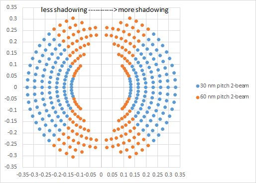
Figure 5. 30 nm pitch imaging requires source points which are separated quite far apart, resulting in a large difference of shadowing on the mask. On the other hand, for 60 nm pitch, two-beam imaging uses points which are closer, and thus less affected by significant shadowing differences. Thus, for 30 nm pitch, photons are effectively divided into two groups, depending on which side they are from.
Implications for EUV patterning
The implication is that layouts with a range of line pitches cannot be supported by EUV except with possible assistance of multipatterning. An easily visualized case is targeting the same CD for 1X, 2X, and 3X pitches. For example, when the 1X pitch is 30 nm, the 2X and 3X pitches of 60 nm and 90 nm respectively can result in dividing the photons primarily among 3 and 8 different coherently produced images, respectively (Figure 6). The stochastics for the 1X 30 nm pitch case is already expected to be bad enough [3], so the 2X and 3X cases would therefore be too severe to allow them to be imaged in a single exposure along with the 1X pitch. Note that changing the illumination from annular to dipole only strengthens the case against EUV single exposure, as forbidden pitches arise [6,7].
Figure 6. 30 nm, 60 nm, and 90 nm pitches split EUV photons into different numbers of coherent images.
Instead, a better alternative would be to have the 2X pitches achieved by blocking alternate lines (e.g., 30 nm width on 60 nm pitch), while the 3X would be achieved by DUV blocking (30 nm on 90 nm pitch). This entails a total of three exposures, one EUV exposure for 30 nm pitch lines (or even a DUV exposure with SAQP due to stochastic risk), one EUV block for 2X, and one DUV block for 3X.
Figure 7. 30 nm, 60 nm, and 90 nm pitch lines cannot be in the same EUV exposure due to stochastic risk, as revealed in Figure 6. The 30 nm pitch lines may first be printed by EUV (or SAQP), followed by a second EUV exposure to block out every other line for 60 nm pitch, and then a third, DUV exposure at 90 nm pitch to block out every three lines.
Thus, we see that small CD-large pitch combinations are worst for stochastic failures in EUV lithography. In fact, this implies that cutting could be subject to stochastic failure risk. Larger half-pitches are the preferred case. Hence, EUV may even follow DUV’s path to self-aligned double patterning (SADP) or even self-aligned quadruple patterning (SAQP).
References
[1] P. de Bisschop and E. Hendrickx, “On the dependencies of the stochastic patterrning-failure cliffs in EUVL lithography,” Proc. SPIE 11323, 113230J (2020).
[2] P. de Bisschop and E. Hendrickx, “Stochastic printing failures in EUV lithography,” Proc. SPIE 10957, 109570E (2019).
[3] J. Church et al., “Fundamental characterization of stochastic variation for improved single-expose extreme ultraviolet patterning at aggressive pitch,” Proc. SPIE 11323, 113230O (2020).
[4] https://www.linkedin.com/pulse/stochastic-behavior-optical-images-impact-resolution-frederick-chen
[5] S. Das et al., “E-beam inspection of single exposure EUV direct print of M2 layer of N10 node test vehicle,” Proc. SPIE 10959, 109590H (2019).
[6] https://semiwiki.com/lithography/283578-a-forbidden-pitch-combination-at-advanced-lithography-nodes/
[7] https://www.rit.edu/~w-lith/research/imagetheory/SPIE_5040-36_full.pdf
Share this post via:



Speculative Execution: Rethinking the Approach to CPU Scheduling