NVM Survey 25 Wide Banner for SemiWiki 800x100 px (1)

On-Chip Power Distribution Networks Get Help from Magwel’s RNi

On-Chip Power Distribution Networks Get Help from Magwel’s RNi
by Tom Simon on 02-02-2017 at 12:00 pm

Counting squares is a useful tool for calculating simple resistance in wires, but falls short in reality when wires deviate from ideal. Frequently the use of RC extraction tools for determining resistance in signal lines in digital designs can be effective and straightforward. However, there are classes of nets in designs that confound extraction tools. Good examples of these are found in power distribution networks. Also, nets found in memory designs are excellent candidates for deeper analysis.

At one end of the spectrum of solutions we find full wave solvers. While they are the most accurate method for analysis of electrical properties in all kinds of metal structures, they are troublesome to apply to complex on chip metal structures. Full wave solvers are difficult to set up, run slowly and output S-parameters, which are vexing to use for subsequent interpretation. Consequently, use of full wave solvers is often limited to analysis of on-chip inductors and capacitors.

The output of RC extractors fall short when complex nets are involved. A typical power or ground net may have thousands or more end points. What matters to the design is the actual resistance at each of these end points. To further complicate solving this problem these nets are often highly interconnected to themselves. The best example of this is a mesh style power or ground net. There are many parallel current paths in these nets, which can greatly complicate the effective resistance between any two points on the network.

Fortunately for designers who need to tune and optimize endpoint resistances in large complex nets, such as power distribution networks, there is an easy to use solution available from Magwel. Their Resistance Network Integrity (RNi) tool provides an intuitive and easy to use approach that provides comprehensive analysis and an interactive interface for finding high resistance segments and endpoints.

Magwel’s RNi uses solver technology that can handle complex interconnect without the difficult set up typically required for other solvers. RNi reads in the layout in GDS and allows the user to select a pad or create a contact point to use as a reference point for the resistance calculation. The RNi technology file comes from information found in foundry supplied ITF files. Once the solver is started, results are available quickly.

The solver extracts the entire net, including vias and metal on all layers. Another benefit is that no stimulus is needed and the design does not have to be LVS clean. It is extremely valuable to be able to plan power distribution networks as early as possible in the design cycle.

RNi calculates the total resistance to all points on the selected net from the contact point or pad that was set at the beginning of the run. It’s easiest to view the results in the tool’s field view. This is a graphical view that uses color to visualize the resistance values. Also, moving the mouse over any point in the net will display the resistance value to that point as a number. Of course, in a large chip, finding a high resistance point can be like finding a needle in a haystack. RNi will quickly list the top values and allows the user to zoom in on the view each of them with a single click on the mouse.

RNi is a natural addition to Magwel’s product line up. Accurate resistance extraction is an absolute necessity for ESD induced voltage drop during discharge events. Magwel is applying its solver based resistance extraction to this problem in its ESDi product. The same technology comes into play during power device gate, source and drain network simulation and analysis in their PTM product family. For more information on Magwel and their solutions for improving design efficiency, reducing power, and increasing reliability, refer to their website here.


An Easy Path to Bluetooth 5-enabled SoC Design

An Easy Path to Bluetooth 5-enabled SoC Design
by Bernard Murphy on 02-02-2017 at 7:00 am

Bluetooth (BT) was never a bit-player in communication but what surprised me is that is already dominating the market, at least as measured by radios sold, and is likely to extend that lead over the next 5 years. Particularly impressive is that BT already leads cellular and WiFi. This strength is certainly influenced by sales into IoT applications but also by what CEVA labels as IoD (internet of digital, that is non-IoT) devices where BT already plays an important role.

You can see where this strength is coming from in a forward-looking survey of applications. By 2021, smartphone applications will still contribute the largest component of volume, but after that, even when you drop PC-related categories there are applications for automotive, home automation, residential lighting, robotics, healthcare and many more. None of taken individually will be a major component of total volume, but there are so many active and growing applications that together they could amount to 50% of total volume.

Let’s start with a little terminology. The BT5 spec (in fact BT specs since 4.0) covers BT classic and BT low-energy (BLE). You can operate in pure classic mode, pure BLE mode or dual-mode. Classic is what made earpieces, speakers, wireless mice and other options so popular. BLE is a big part of what made BT a serious player in IoT. Dual-mode offers access to both options and is now common in smartphones, Bluetooth headsets/earbuds and speakers. An interesting point that initially confused me is that many of the features are optional per the standard, leading to potential confusion about what makes up BT5. In what follows, I will use the term to mean the full spec with all options.

The appeal of BT and the reason for this growth is in part that it offers low infrastructure cost because it can leverage existing hubs like smartphones, laptops, tablets and digital TVs (particularly where dual mode is supported in those hubs). It is low power (under 10mW at peak, down to uW in standby) and it offers robust and secure communication through frequency-hopping and built-in security/privacy features. BT5 builds on these existing strengths through even longer range (up to 1km line of sight), lower power and improved frequency-hopping through a more pseudo-random approach, supporting more devices communicating at the same time in a denser environment.

CEVA (Franz Dugand, Director connectivity BU) jointly presented with CSEM (Nicholas Raemy, head analog/RF design) in a webinar last week their joint solution for easy BT5 integration for BLE use-models. CEVA in their RivieraWaves product line-up provides the baseband controller and software. They also provide modem and RF blocks optimized for dual-mode use. The CSEM package adds modem and RF components optimized to BLE use. In either approach you can adopt the whole solution as a turnkey package or mix and match with your own or other IPs of your choice.

But if you do mix and match, CEVA advise you check specs carefully. Since many of the features are optional, an IP vendor can legitimately claim compliance with the standard without supporting all features. Naturally the solution offered here supports all features, including the optional ones, including among these all performance options and co-existence with 802.15.4 (ZigBee/Thread) and Wi-Fi.

The RivieraWaves baseband IP supports Bluetooth Low Energy, Bluetooth Classic and Bluetooth dual-mode and includes AES 128-bit encryption. Riviera Waves BT has a pretty impressive pedigree, licensing since 2000 and including Renesas, NXP, Spreadtrum and Atmel as customers, with 70+ design wins in PC, mobile, medical, automotive wearable and other applications.

The CSEM icyTRX IP offers a BLE solution for the modem and RF sections. This claims lowest power consumption in the market and a tiny form-factor, available in 65 or 55nm processes from several foundries. It is designed for a very simple interface with the CEVA baseband IP (9 signals) and can operate in low energy (1/2 Mbps) and long-range (500/125kbps) modes. CEVA and CSEM already have 6 customers for the joint solution.

Several general questions on the standard came up. I found the answers educational so I’ll add them here. One was on target applications for 2Mbps. Franz said that a big application will be firmware update over air, another would be for audio, e.g. for hearing aids. He also made an interesting comment on mesh support, noting that this is not directly part of the BT5 spec and can be done with existing chipsets. Smart mesh support is yet to be finalized in the standard and should be more efficient and provide better power management.

Applications for long-range support are particularly around home-automation, including long-range lighting, window/door control, temperature sensors and should be able to cover the outside area also, e.g. for watering controls. One other question was on whether smartphone vendors are offering BT5 yet. Franz said that those vendors are likely to be followers rather than leaders in this space since they will look for ecosystem support (which is one reason why dual-mode support continues to be an valuable option). He thought we may start to see smartphone options by the end of the year.

You can watch the Webinar HERE.


SPIE Advanced Lithography and Synopsys!

SPIE Advanced Lithography and Synopsys!
by Daniel Nenni on 02-01-2017 at 7:00 am

SPIE is the premier event for lithography held in Silicon Valley and again Scotten Jones and I will be attending. EUV is generally the star of the show and this year will be no different now that TSMC has committed to EUV production in 2019.

Last year at SPIE, TSMC presented the history of EUV development from the beginning in 1985 as Soft X-Ray to the name change to EUV in 1993. TSMC forecasted that they will “exercise” EUV at 7nm and will introduce EUV for production use at 5nm. TSMC now says they will in fact insert EUV into 7nm in the second year of production (2019) in preparation for EUV at 5nm in 2020. So finally we will have EUV in production after more than 30 years of R&D and so many false starts!!!!!

This year Intel will again keynote SPIE and present “EUV readiness for HVM” and Samsung will again present “Progress in EUV Lithography toward manufacturing”. Scott will do thorough blogs on the conference as he has in the past. You can read Scott’s very technical event related blogs HERE. If you are attending SPIE it would be a pleasure to meet you, absolutely.


A new event at this year’s SPIE is the Synopsys Technical Forum where you will learn the latest on Synopsys Manufacturing’s mask synthesis, mask data prep and lithography simulation solutions. The Tech Forum is peer-to-peer, giving you the opportunity to hear how your lithography colleagues have addressed the challenges of 10nm and 7nm.

Overview

Synopsys provides industry-proven EDA solutions to meet the demands of today’s advanced IC manufacturing processes while setting the standard in platform flexibility to enable innovative and custom solutions for next-generation technology nodes. Synopsys’ comprehensive Mask Synthesis, Mask Data Preparation, TCAD, and Yield Management tools provide leading edge performance, accuracy, quality, and cost of ownership for all your production and development needs.

Synopsys Technical Forum Agenda

[TABLE] cellpadding=”5″ style=”width: 100%”
|-
| align=”center” valign=”top” | Time
| valign=”top” style=”width: 400px” | Presentation Title
| align=”center” valign=”top” | Speaker
| align=”center” valign=”top” | Company
|-
| valign=”top” | 12:30
| colspan=”3″ valign=”top” | Registration & Lunch
|-
| valign=”top” | 1:00
| valign=”top” | Welcome & Introduction
| align=”center” valign=”top” | Howard Ko
| valign=”top” | Synopsys
|-
| valign=”top” | 1:30
| valign=”top” | DTCO Metrics for Patterning Design Arc Definition at 7nm and Beyond
| align=”center” valign=”top” | Derren Dunn, Ph.D.
| valign=”top” | IBM
|-
| valign=”top” | 2:10
| colspan=”3″ valign=”top” | Break & Prize Drawing #1
|-
| valign=”top” | 2:25
| valign=”top” | ILT Optimization of EUV Masks for Sub – 7nm Lithography
| align=”center” valign=”top” | Kevin Lucas
| valign=”top” | Synopsys
|-
| valign=”top” | 3:05
| valign=”top” | Keynote: Advanced Patterning and Litho Options for Challenging Geometries
| align=”center” valign=”top” | Hyunjo Yang
| valign=”top” | SKHynix
|-
| valign=”top” | 3:50
| colspan=”3″ valign=”top” | Thank You & Drawing #2
|-


Visit Synopsys at Booth #206

Tuesday, February 28: 10:00 a.m. to 5:00 p.m.
Wednesday, March 1: 10:00 a.m. to 4:00 p.m.

Location
San Jose Convention Center
Directions

Synopsys Technical Program

Security applications for direct-write lithography(Keynote Presentation)
Mike Borza, Synopsys Inc. (Canada) [10144-3]

Correlation of experimentally measured atomic scale properties of EUV photoresist to modeling performance: an exploration

Yudhishthir Kandel, Synopsys, Inc. (USA); Jonathan Chandonait, SUNY Polytechnic Institute (USA); Sajan Marokkey, Lawrence S. Melvin III, Qiliang Yan, Benjamin D. Painter, Synopsys, Inc. (USA); Gregory H. Denbeaux, SUNY Polytechnic Institute (USA) [10143-7]

Modeling EUVL patterning variability for metal layers in 5nm technology node and its effect on electrical resistance

Weimin Gao, Synopsys GmbH (Belgium); Lawrence S. Melvin III, Synopsys, Inc. (USA); Itaru Kamohara, Synopsys GmbH (Germany); Vicky Philipsen, Vincent Wiaux, Eric Hendrickx, Ryoung-Han Kim, IMEC (Belgium)[10143-14]

Advanced fast 3D DSA model development and calibration for design technology cooptimization

Kafai Lai, IBM Thomas J. Watson Research Ctr. (USA); Balint Meliorisz, Thomas Mülders, Hans-Jürgen Stock, Synopsys GmbH (Germany); Sajan Marokkey, Synopsys, Inc. (USA); Wolfgang Demmerle, Synopsys GmbH (Germany); Chi-Chun Liu, Cheng Chi, Jing Guo, Albany NanoTech (USA)[10144-16]

Experimental characterization of NTD resist shrinkage
Bernd Küchler, Thomas Mülders, Synopsys GmbH (Germany); Hironobu Taoka, Nihon Synopsys G.K. (Japan); Weimin Gao, Synopsys NV (Germany); Ulrich Klostermann, Synopsys GmbH (Germany); Sou Kamimura, FUJIFILM Corp. (Japan); Grozdan Grozev, FUJIFILM Corp. (Belgium); Masahiro Yoshidome, Michihiro Shirakawa, FUJIFILM Corp. (Japan); Waikin Li, IMEC (Belgium)[10147-14]

Modeling of NTD resist shrinkage
Thomas Mülders, Hans-Jürgen Stock, Bernd Küchler, Ulrich Klostermann, Wolfgang Demmerle, Synopsys GmbH (Germany)[10146-21]

Source defect impact on pattern shift

Artak Isoyan, Chander Sawh, Lawrence S. Melvin III, Synopsys, Inc. (USA) [10147-21]
Cost effective solution using inverse lithography OPC for DRAM random contact layer
Jinhyuck Jeon, Jae-Hee Hwang, Jaeseung Choi, Seyoung Oh, Chan-Ha Park, Hyun-Jo Yang, SK Hynix, Inc. (Korea, Republic of); Thuc Dam, Synopsys, Inc. (USA); Munhoe Do, Dongchan Lee, Synopsys Korea Inc. (Korea, Republic of); Guangming Xiao, Jung-Hoe Choi, Kevin Lucas, Synopsys, Inc. (USA)[10148-8]

Resist 3D aware mask solution with ILT for resist failure hotspot repair
Guangming Xiao, Kosta S. Selinidis, Kevin Hooker, Synopsys, Inc. (USA); Wolfgang Hoppe, Synopsys, Inc. (Germany); Thuc Dam, Kevin Lucas, Synopsys, Inc. (USA)[10147-25]
New methodologies for lower-K1 EUV OPC and RET optimization
Kevin Hooker, Yunqiang Zhang, Kevin Lucas, Aram Kazarian, Joshua P. Tuttle, Guangming Xiao, Synopsys, Inc. (USA)[10143-45]

Exposure source error and model source error impact on optical proximity correction

Lawrence S. Melvin III, Artak Isoyan, Chander Sawh, Synopsys, Inc. (USA)[10147-32]

Guiding gate-etch process development using 3D surface reaction modeling for 7nm and beyond (Invited Paper)
Derren N. Dunn, IBM Research (United States); John R. Sporre, Univ. of Illinois at Urbana-Champaign (United States); Ronald Gull, Synopsys Switzerland, LLC (Switzerland); Peter Ventzek, Tokyo Electron America, Inc. (United States); Alok Ranjan, TEL Technology Ctr., America, LLC (United States) [10149-36]

Synopsys Posters

Compact modeling for the negative tone development processes
Lawrence S. Melvin III, Synopsys, Inc. (USA); Chun-Chieh Kuo, Synopsys, Inc. (Taiwan); Jensheng H. Huang, Synopsys, Inc. (USA)[10147-63]

Addressing optical proximity correction (OPC) challenges from highly nonlinear OPC models
Stephen Jang, Synopsys, Inc. (USA) [10147-64]

Stitching-aware in-design DPT auto fixing for sub-20nm logic devices
Soo Han Choi, David Pemberton-Smith, Sai Krishna K.V.V.S, Synopsys, Inc. (USA)[10148-46]
Using pattern matching to increase performance in hotspot fixing flows
Bradley J. Falch, Synopsys, Inc. (USA) [10148-49]


Finding Transistor-level Defects Inside of Standard Cells

Finding Transistor-level Defects Inside of Standard Cells
by Daniel Payne on 01-31-2017 at 12:00 pm

In the earliest days of IC design the engineering work was always done at the transistor-level, and then over time the abstraction level moved upward to gate-level, cell-level, RTL level, IP reuse, and high-level modeling abstractions. The higher levels of abstraction have allowed systems to be integrated into an SoC that can use billions of gates. All of that is wonderful and a powerful part that enables our global semiconductor economy, however if you are concerned about the quality and reliability of your SoC then keeping the Defects Per Million (DPM) very low is a key metric that must be adhered to. Having cell-aware diagnosis is essential to finding any manufacturing flaws at the transistor level, inside of standard cells, the basic building blocks of semiconductor IP libraries.

I connected with my contacts at Mentor Graphics to see what they are doing in this area of cell-aware diagnosis. Geir Eide has written a White Paper titled: Expose Transistor-Level Yield Limiters with Cell-Aware Diagnosis. I’ll share what I found it from this seven page document.

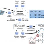
Like with any type of testing, you must first have a model of your standard cell library. In this case it starts with a transistor-level model that includes layout information plus the SPICE netlist. Many manufacturing defects occur based upon how the IC layout is arranged, just think about adjacent metal wires that potentially could short circuit. Taking a look at a diagram will help explain this new approach:

Starting at the bottom of the diagram we see that both a SPICE netlist and GDSII layout are inputs to the Cell-aware fault model generation step, this is where fault models are created by analog simulation for each of the potential defects extracted from the cell layout – think about shorts, opens and resistive shorts. In the diagram there’s an open circuit at node D71, which is inside of a particular standard cell. During the fault model generation a SPICE circuit simulator has predicted the behavior of having an open at node D71, so when we run our ATPG patterns then this particular fault can be detected, and during the diagnosis phase it will pinpoint the open circuit to be inside this cell instance at the specific XY coordinates. Think of how much time this approach will save your engineers that are performing Physical Failure Analysis (PFA) in order to improve the yield for a new SoC.

Related blog – New Frontiers in Scan Diagnosis

Product engineers are going to love this new ability, because it will make their jobs much more productive. So instead of just knowing that one cell instance has a defect somewhere, they now would now that inside of this cell instance at a specific coordinate, there is a defect, like an open or a short. Having this cell-aware diagnosis the yield problems can be quantified over a number of chips so that you can concentrate on PFA based upon the highest percentage issues found first.

Fault Model Creation
Now that we’ve seen kind of the big picture, let’s take a closer look at each of the steps starting with fault model creation. You create cell-aware fault models once per technology. During fault model generation the probability of an open or short between layers is determined, so for example in the following figure we know that bridging defect D45 has a high probability while defect D46 has a very low probability:

An analog simulator like Eldo is then used to simulate each of the potential defects against an exhaustive set of inputs to see if any input combination will produce an output result different from a good circuit. This data about which cell inputs can detect internal faults becomes part of the new fault model.

Diagnosis
During cell-aware diagnostics we see that the inputs are the SPICE netlist, layout, fault library, ATPG patterns and tester fail data:

Every failing pattern is traced to find initial candidates using pattern matches. The best matching symptoms are identified and reported in the right-hand side. For me the biggest wow factor is the diagnostic ability to pinpoint the XY coordinates of each defect like opens and shorts between metals or poly layers. As you click on a text failure name, then you can see in the layout where this defect happened:

Silicon Results
Up until now this all sounds so theoretical and practical, yet does it really correlate to actual silicon failure mechanisms in wafers? The short answer is Yes, according to a range of companies doing silicon designs from 160nm planar CMOS down to 14nm FinFET. One big name that uses this cell-aware diagnosis is AMD and here’s where they found an open contact defect inside of a full adder circuit:

This one particular cell used 24 transistors and had 277 internal faults that could be tested based upon the extracted defects. In the old approach you would only know that this cell had a failure, while with the cell-aware approach now available you will know that four cell internal suspects would cause this particular failure. In the top-down view of the IC layout on the left we see all four of these suspects highlighted. The photo on the right shows a cross-sectional view of where the un-landed contact was pinpointed during failure analysis. You can quickly conclude that using this cell-aware approach is a great boon for PFA.

A second example shows how cell-aware analysis of a 160nm automotive chip pinpointed an open circuit on a Poly layer:

The IC layout is shown on the left in top view, then the middle is the silicon layout top view, finally the rightmost photo zooms into the missing Poly defect.

Conclusion
The goal of silicon manufacturing is to produce perfect chips, every time, however when there is a manufacturing flaw then the burden shifts to the product and yield engineers to quickly pinpoint the source of the failure in order to understand the root cause and propose a remedy or yield improvement approach. By using a cell-aware tool that models transistor-level defects inside of cells, the analysis work greatly speeds up, providing swift feedback about failures and yield. You could use this kind of a tool for both single-part diagnosis or yield analysis.

Read the complete 7 page White Paper here
.


Computability 2.0?

Computability 2.0?
by Bernard Murphy on 01-31-2017 at 7:00 am

There’s muttering among computing fundamentalists that perhaps we ought to revisit the definition of computability given recent advances in methods of computing, especially machine learning and quantum computation.

Computability is about what can and cannot be computed, either by a human or non-human computer. This is a topic most of us associate with Alan Turing, the Turing machine and the Halting problem but the correspondence with human calculators is better expressed in the (related) Church-Turing thesis. It’s a thesis (hypothesis) because we don’t have a formal definition for what a human can and cannot calculate, but it’s widely believed to hold – that there is a potentially exact correspondence, in principle, between what a human and a Turing machine can calculate (though typically at very different speeds).

Can quantum computing or deep learning somehow transcend these bounds? Some theorists have proposed that hyper-computation – computation able to solve problems unsolvable by a Turing machine – should be possible at least in principle.


One such case was made in 1995 for a hypothesized neural net. The author of that paper starts by restricting the weights on nodes to be integers, which is of course possible. This is then relaxed to allow rational numbers – also possible. The theoretical range of problems that could be solved by such machines is countably infinite since integers and rationals are both countably infinite. This is still no more capable than a Turing machine, but then the author takes the next step, making the weights real numbers. As a limit to progressively more accurate approximations, this is still possible.


An interesting thing about reals is that there are vastly more than there are countable numbers, such as integers or rationals. Some are real representations of integers and rationals, some are irrational, like √2 or pi or e, and each of these is computable on a Turing machine to arbitrary accuracy using a finite algorithm. There is a countable infinity of these computable numbers because finite algorithms can be listed in some order, which makes them countable, and even if each can generate a countably infinite set of numbers, the total set of numbers that can be generated is the product of two countable infinities, which is still countably infinite.

The total set of reals is uncountable, which means that almost all reals are uncomputable numbers for which no finite algorithm is possible (an infinite algorithm for a given real is always possible – simply list out the digits in whatever base you use to express the number). Now suppose you use uncomputable numbers as weights in the neural net. Then in principle it would be possible for the net to calculate an uncomputable (in Church-Turing terms) result which could not possibly be calculated by a Turing machine. Does this hold out the promise that you could possibly, at least in theory, build a machine that could solve problems like the Halting problem?

Unfortunately no, because the argument is flawed. You can only compute an uncomputable result if you start with uncomputable weights. Either those must be computed on a Turing-like machine – which is not possible because Turing machines can only generate computable numbers – or you must assume the existence of a machine which can generate uncomputable numbers – which is circular reasoning. There is one other option – it is possible in principle to generate uncomputable random numbers (after all, you want random numbers to be uncomputable). The problem here is that while the weights and the result may be uncomputable, they will also be unusable – you have no control over what the net will calculate.


A different case has been made for quantum computing but this is primarily a performance argument rather than a feasibility argument (which is the substance of Church-Turing). It is true that for a narrow range of problems, quantum computing can be as much as exponentially faster than traditional/Turing computing but Church-Turing only cares if computation completes in finite time (using a finite algorithm on a finite machine), not how quickly it completes.

However one theoretical suggestion uses an infinite superposition of quantum states, which could in principle transcend the countability limit. There are obviously some physical problems in the proposal, but the idea is intellectually appealing in at least one sense. Combining a superposition of a countable infinity of quantum states with exponential performance allows (in principle) access to 2 [SUP]countable infinity[/SUP] states which is precisely the size of the set of reals. The machine could in theory access that complete set, though sadly you still must provide algorithms and inputs to do something useful, which would still limit calculations to a countable set.

Another physical assist requires that a (Turing) computer orbit a spinning black hole. It seems that relativistic time dilation around that massively warped space-time can be organized such that a programmer can interact with the machine in finite time but the computation in the frame of the machine can evolve in infinite time, allowing an infinite computation to complete in finite time for the programmer. However this is an approach unlikely to be tested any time soon.

One final apparent counter-argument. Humans can reason about infinite objects in quite constructive ways. For example, proof of the Goldstein theorem depends on this kind of reasoning. So if humans can do this, can machines also perform the same kind of reasoning? There’s no obvious reason why not. Does this break the Church-Turing thesis? No. Because these cases use finite algorithms which complete in a finite number of steps, reasoning about abstract infinite objects. But solving an uncomputable problem requires an infinite number of steps. You can’t reason about infinity – you must go there.

None of this means that novel forms of computing aren’t exciting and (for some problems) very useful. They can certainly dramatically improve efficiency – that’s all part of advancing technology. But we should temper our expectations to what is asymptotically achievable; physical and mathematical limits don’t bend to enthusiasm. And there is a corollary – if humans can’t even conceivably compute a certain result (allowing for multiple people and a countable number of generations working on the problem) then it is quite likely that machines can’t conceivably do it either. And vice-versa. Church-Turing remains the upper bound for computability and at least in principle machines can never be fundamentally smarter than us (though they can certainly be much faster).

You can read more and peruse a challenging list of references HERE. I found a very nice critique of hyper-computation HERE (from which my neural net discussion is derived).

More articles by Bernard…


Four Steps for Logic Synthesis in FPGA Designs

Four Steps for Logic Synthesis in FPGA Designs
by Daniel Payne on 01-30-2017 at 12:00 pm

I remember meeting Ken McElvain at Silicon Compilers for the first time back in the 1980’s, he was a gifted EDA tool developer that did a lot of coding including logic synthesis, a cycle-based simulator and ATPG. Mentor Graphics acquired Silicon Compilers with Ken included, and he continued to create another logic synthesis tool at Mentor, however the allure of starting up his own company set in and Ken then founded Synplicity, eventually acquired by Synopsysin 2008. After all of these years the Synplify tool is still setting the high-water mark for logic synthesis in FPGA devices. Joe Mallett at Synopsys wrote a four page white paper recently, so I read it to better understand the four steps for logic synthesis in FPGA designs:

[LIST=1]

  • Initial design setup and configuration
  • Achieve first working hardware with accelerated run times
  • Perform high visibility FPGA debug
  • Tune the system for performance in the smallest area

    Initial Design Setup and Configuration
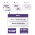
    Gone are the days of starting with a blank sheet as a design starting point, instead to get to market more quickly the best practice is to re-use IP blocks from previous designs, re-use IP from other groups within the company, purchase new IP from trusted vendors, or use IP provided by the FPGA vendor. These IP blocks will typically have RTL source code along with constraint files for the logic synthesis tool. Here’s the design flow showing how the RTL code, IP cores and constraints go into the Synplify logic synthesis tool, creating your gate level netlist and technology-specific output files:

    First Working Hardware
    One acronym that you quickly learn with logic synthesis is Quality of Results (QoR), which means reaching the desired clock speeds, input setup and hold times, output delay times, and fewest number of gates, all at an acceptable power level. A smart logic synthesis tool like Synplify can quickly infer what clocks are in your design, however you can always define internal clocks as needed to further constrain the design and achieve objectives.

    Related blog – One FPGA synthesis flow for different IP types

    When constraints for logic synthesis are all in place, then the Synplify tool does its work to generate the compiled design, ready for physical implementation by the FPGA vendor place and route tool. To speed up logic synthesis run times the approach used by Synplify is called distributed synthesis. Using runtime acceleration in Synplify gives you results quicker, and you can even do incremental synthesis on parts of your design are changing. Most modern EDA tools have adopted this approach of distributed computing to get results more quickly. You get to decide which is best for your project, running Synplify on just one machine, or across a server farm.

    High Visibility FPGA Debug
    Debug and verification of your new design will likely take more time and effort than the original design entry does. So how do you get visibility and traceability of your complex design with all of those IP blocks included? The good news is that you can select any set of internal signals for sampling or triggering during simulation using Identify integration, something built-in to Synplify. With this list of selected signals you now have an instrumented design, and using the debugger you can analyze results at system speeds which makes for faster design debugging.

    As you debug your design and make changes, then there’s a re-compile required and with Synplify you can do a parallel incremental synthesis, as shown below:

    This accelerated approach lets you get in multiple iterations per day, to help meet your time to market deadlines.

    Tuning the System for Performance
    When the design meets all of the functional requirements and debug is behind us, then the fourth step is focused on reaching the total system-level performance. The FPGA synthesis tool can be further constrained to reach timing metrics, but if you over-constrain the design then it will just increase the run times for synthesis and the vendor place and route tools. Here are some best practices to consider when using Synplify to tune for timing QoR:

    • For failing timing paths look at the logic along the path and see if you can use fewer levels of logic
    • Follow recommended RTL coding guidelines for both synthesis plus place and route (think Apnotes)
    • Using timing models for black boxes (i.e. IP blocks)
    • During place and route increase the placement effort if there’s room for improvement in the placement
    • Fix any synthesis project errors prior to starting place and route
    • Review the timing analysis report to direct your constraints
    • Reduce high fanout nets in Synplify, add more pipelining and try sequential optimizations and re-timing
    • Find and remove any un-needed resets
    • Choose your critical paths to be on the same die of multi-die FPGA devices

    Related blog – Why FPGA synthesis with Synplify is now faster

    Summary
    FPGAs have grown dramatically in popularity from the earliest days when used only for glue logic between expensive ASICs, to now encompassing processors, complex IP blocks, high-speed serial channels, optimized memories, and millions of gates. By using a logic synthesis tool like Synplify in the design flow you will find that these four steps can get done at a rapid pace.

    Read the complete four page white paper here


  • CEO Interview: David Dutton of Silvaco

    CEO Interview: David Dutton of Silvaco
    by Daniel Nenni on 01-30-2017 at 7:00 am

    Silvaco has undergone one of the most impressive EDA transformations so it was a pleasure to interview the man behind it. David Dutton’s 30+ year career started at Intel, Maxim, and Mattson Technology where he led the company’s turnaround and finished as President, CEO, and board member. David joined Silvaco as CEO in September of 2014 and the rest is history in the making.

    This is a picture of Silvaco’s corporate offices around the world. Their Taiwan office (beige building) is between the Hotel Royal where I stay and TSMC Fab 12, across the street from Starbucks. So yes, I pass by it quite frequently.

    Give us a brief introduction to Silvaco, including an overview of your current operations and product offerings?
    Silvaco is a leading provider of EDA tools, used for process and device development and for analog, digital, mixed-signal, power IC, and memory design. The portfolio includes tools for TCAD, Frontend, Backend, simulations, power integrity sign off, reduction of extracted netlist, variation analysis and also IP cores. Overall Silvaco delivers a full TCAD-to-signoff flow for vertical markets including display, power electronics, optical devices, radiation & soft error reliability, analog and HSIO design, library and memory design, advanced CMOS process and IP development.

    The company is headquartered in Santa Clara, California, and has a global presence with offices located in North America, Europe, Japan, and Asia.

    What do you look forward to in 2017 for Silvaco?
    We are coming off one of our strongest years ever with about 30% year over year growth on bookings. Silvaco has many things to look forward to this year. In 2016 we saw great new product adoption with Victory 3D, Variation Manager, and Jivaro RC reduction tools, along with SmartSpice and Expert being utilized down to 7nm by customers. We established an IP division which brings Silvaco into the fastest growing area of the Circuit Design market. We welcomed new teams from three acquisitions – Infiniscale, edXact and IPExtreme. The Silvaco family sure has grown in 2016. The semiconductor industry continues to change, and Silvaco is using these changes to aggressively grow for the future of Silvaco and our customers. In 2017 we will continue to invest in improving our products and making acquisitions that advance our position.

    Which markets do you feel offer the most and best opportunities for your products over the next few years and why?
    The key markets for Silvaco’s products over the next few years are Display, Power, Automotive and advanced CMOS. On the display side, Silvaco’s product suite is used for design of both thin-film transistor (TFT) LCD displays and organic LED (OLED) displays. With the growth in adoption of smartphones, flat-screen TVs, smartwatches and more this is an area of increasing importance. Almost all manufacturers of displays use the Silvaco suite for design and most of these designs are in high-volume manufacturing. The display market demands specific capabilities from TCAD and EDA tools, that are not mainstream, Silvaco works closely with our display customers to understand their needs and has been investing in development specific to this growing segment. We view power IC devices as a key market due to automotive, industrial and medical systems that are all increasing in IC content. In addition, Silvaco has a long history of leadership in the compound semiconductor device market which puts us in a unique position to leverage our leadership in this growth area. The automotive market is not only critical for our display and power design tools, but also our IP division has CAN FD and controllers that are key to the development of the autonomous driving market. We have also launched the MIPI I3C family of IP for sensor connectivity and IoT applications.

    Advanced CMOS is an area Silvaco is not known for, but we have made a significant investment to change this in the last year. Many of our design tools are involved at 16nm and below. Silvaco is helping customers down to 7nm with our CleverTM 3D RC extraction tool. Our Variation Manager, Viso, Invar and Jivaro RC reduction tools help our customers increase performance at signoff. Our SmartSpice is utilized down to 7nm due to its accuracy and performance, and we are constantly working to improve the performance of our products.

    There is a wave of consolidations going on in the semiconductor industry right now. How do all these Mergers and Acquisitions affect EDA providers like Silvaco?
    It seems like not a day goes by that there is an announcement about yet another semiconductor merger. There is no doubt that our industry is changing. The current group of mergers and acquisitions of semiconductor companies seems to be driven by at least three forces: The first reason is that the design and development costs at the advanced nodes are increasing due to complexity, which drives some companies to seek mergers to effectively pool their resources. The second reason is that we are seeing a shift from semiconductors being driven by mobility to the emergence of automotive and IoT drivers. For example, the Qualcomm and NXP merger was due to Qualcomm, a leader in mobile, recognizing the shift and acquiring NXP who is a leader in automotive and IoT areas. A third force is that China is investing in semiconductor growth and is doing a lot of acquisitions to accelerate their growth. We see Silvaco is in the position to get stronger as this consolidation wave rolls through, and even our position in China will strengthen through this time. Some trends are playing into Silvaco’s strengths such as display growth, power devices for automotive and analog mixed signal for IoT. Silvaco has completed four acquisitions in the last 18 months to help accelerate our growth, and they are all contributing to our expansion. We also announced our agreement to merge with Global TCAD Solutions, GTS at IEDM 2016. The transaction is expected to be completed soon.

    How is Silvaco taking the initiative in growing in emerging economies?
    For Silvaco, we are more committed to our growth more now than ever before. We also recently announced the opening of our office in Shanghai, China. Due to this growth, we see the need for technical talent on a global scale. We cannot rely on just one region to supply all our engineers and scientists. Silvaco already has development activity in the US, UK, France, Austria, and Japan. We are adding Russia and India technical offices as well due to the fact that these regions have grown solid technical resource bases for the software industry. We host Silvaco Symposiums in regions around the world to support the local design ecosystem. For IP, after a hugely successful REUSE 2016 in Mountain View, we are planning a REUSE 2017 show in Shanghai.

    Also Read:

    CEO Interview: Toshio Nakama of S2C

    CTO Interview: Mohamed Kassem of efabless

    IEDM 2016 – Marie Semeria LETI Interview


    ISS Gary Patton Keynote: FD-SOI, FinFETS, and Beyond!

    ISS Gary Patton Keynote: FD-SOI, FinFETS, and Beyond!
    by Scotten Jones on 01-28-2017 at 12:00 pm

    Two weeks ago the SEMI ISS Conference was held at Half Moon Bay in California. On the opening day of the conference Gary Patton CTO of GLOBALFOUNDRIES gave the keynote address and I also had the chance to sit down with Gary for an interview the next day.


    Continue reading “ISS Gary Patton Keynote: FD-SOI, FinFETS, and Beyond!”


    SoC Integration using IP Lifecycle Management Methodology

    SoC Integration using IP Lifecycle Management Methodology
    by Daniel Payne on 01-27-2017 at 12:00 pm

    Small EDA companies often focus on a single point tool and then gradually over time they add new, complementary tools to start creating more of a sub-flow to help you get that next SoC project out on time. The most astute EDA companies often choose to partner with other like-minded companies to create tools that work together well, so that your CAD department doesn’t have to cobble together a working solution. I was pleased to find two such EDA companies that have worked well together on SoC integration using IP lifecycle management methodology, Methodics and Magillem.

    There are four tenets to this particular EDA tool interface:

    [LIST=1]

  • Bring IP management to all lifecycle stakeholders through an integrated platform
  • Optimize IP governance
  • Connecting IP design reuse and the IP governance process
  • Manage defects and traceability so that IP modifications are propagated and IP quality improves

    From the Methodics side they offer IP lifecycle management so that SoC design companies have control over both the design and integration of internal and external design elements: libraries, Analog, digital, stand-alone IP. You get traceability and easier reuse by coupling the IP creators with every IP consumer. Collaboration between designers is enabled by use of a centralized catalog, automated notifications, flexible permissions and integrated analytics.

    Related blog – CEO Interview, Simon Butler of Methodics

    Over on the Magillem side you find tools that are IP-Xact based which is derived from IP-reuse methodology to help solve the challenge of maintaining consistency between different representations of your system, by using a single source of data for your specification, hardware design, embedded software and even documentation.

    The Methodics tool is called ProjectIC (yellow), and here’s how it works with Magillem (red) at a conceptual level:

    Now that we’ve seen the big picture, let’s delve one layer lower and start to look at how these two tools create a workflow:

    Related blog – IC Design Management, Build or Buy?

    This workflow will benefit designers in several ways:

    • IP standardization through IP-XACT
    • Fast IP configuration
    • Intelligent IP integration
    • IP design rule checking
    • Hierarchical IP version & bug tracking
    • IP cataloging
    • Automated Magillem reassembly when a workspace is updated
    • Results annotated back to the IP version
    • Notifications automatically sent based on subscription model
    • Takes advantage of the ProjectIC triggers /workflow engine
    • Plugs a major hole in the RTL assembly methodology

    Engineers are always curious about how integrations work under the hood, so the engines from ProjectIC and Magillem communicate with each other transparent to the end-user, so that each workspace load and update action triggers an executable script that runs Magillem in the user’s workspace:

    Related blog – 5 Reasons Why Platform Based Design Can Help Your Next SoC

    Stepping up a level, here’s what a tool user sees when running the ProjectIC tool:

    So this integration is up and running, ready to help out today. The next version of the integration has three refinements:

    • IP-XACT attributes auto-populated on IPs in ProjectIC
    • Changing configurations will automatically trigger IP-XACT attribute refresh
    • Results of multiple workflows will be visible in a single pane

    Summary
    They say that necessity is the mother of all invention, so it’s refreshing to see that two EDA vendors have taken the time to define, build and test an integration between their tools that will directly help out SoC projects in their quest to be bug-free, and work the first time.


  • Timing Closure Complexity Mounts at FinFET Nodes

    Timing Closure Complexity Mounts at FinFET Nodes
    by Tom Simon on 01-27-2017 at 7:00 am

    Timing closure is the perennial issue in digital IC design. While the specific problem that has needed to be solved to achieve timing closure over the decades has continuously changed, it has always been a looming problem. And the timing closure problem has gotten more severe with 16/14nm FinFET SoCs due to greater distances between IPs, higher performance requirements and lower drive voltages. The timing closure problems will only get worse in 10nm and 7nm SoCs.

    By today’s standards, the complexity of early timing closure challenges seems quaint. Initially on-chip delays were dominated by gate delays. Later on, as the process nodes shrank, wire delays became the main factor. Wire lengths grew longer and wires became thinner and developed higher aspect ratios. The taller thinner wires exhibited increased capacitive and coupling delays aggravated by resistive shielding.

    Still, designers were able to address these issues with logic changes, buffer insertion and clock tree optimization. For many years clock tree synthesis (CTS) was neglected by the major P&R vendors. Around 2006 Azuro shook up the CTS market, realizing big gains in performance, area and power reductions with their improved CTS. Cadence later acquired them and now we see attention to improving CTS from Synopsys as well. Big changes have occurred with concurrent logic and clock optimization.

    But the problem of timing closure occurs not only inside of P&R blocks but also between them. Often within blocks it is possible to avoid multi-cycle paths. However, connections between blocks at nodes like 28nm and below are not so easy to deal with. According to Arteris, with a clock running at 600MHz, you can reasonably expect ~1.42ns of usable cycle time per clock cycle. Assuming a transport delay of .63 ns/mm, it is only possible to cover 2.2mm before registers need to be inserted into a data line. And in most 28 nm SoCs, there are a large number of paths which are longer than 2.2mm.

    The process of improving timing becomes myriad, with designers torn between a huge number of trade offs. Low threshold gates are faster but can wreak havoc with power budgets. Likewise adding pipeline stages for interconnect between major blocks must be weighed carefully because of power and resource limitations. Ideally chip architects can look ahead and anticipate when there will be timing issues later in the flow as chip assembly is taking place. However, this does not always work out as planned. The burden often falls to the backend place-and-route team to rectify unaddressed timing closure issues.

    Furthermore, when timing closure issues at the top level are identified late in the flow, they can necessitate iterations back to the front end team, causing massively expensive delays. The history of digital IC design is filled with innovations to deal with timing closure. Early placement and routing tools were the first tools used to address timing issues. They were quickly followed by floor planning tools. The new floor planning tools were very good at estimating IP block parameters, but not so good at optimizing the placement of the interconnect that exists between the IP blocks.

    The designs most prone to difficult timing issues are large SoCs at advanced nodes. Their complexity has grown explosively. For timing closure within blocks history has shown that linkages with the front end can help back end tools do their job better. The same is likely with connections between blocks.

    In fact, over the last couple of years we have seen increasingly sophisticated approaches to top level interconnect in SoCs. One example is the adoption of Network on Chip (NoC) for making connections between blocks more efficient, providing reduced area, and offering higher performance with lower power. Arteris, a leading provider of Network on Chip technology has recently hinted that NoC may be key in gaining further improvements to top level timing closure.

    The largest SoCs, CPUs and GPUs are scaling up in size dramatically. The upper bounds have reached over 10-15 Billion transistors. Timing closure in these designs is paramount. However, the scale of the problem has moved beyond the ability of one part of the flow to provide a comprehensive solution. Front to back integration will be essential. I predict that 2017 will prove to be a pivotal year for solutions to timing closure in SoCs.