RVN! 26 Banner revised (800 x 100 px) (600 x 100 px)

LiDAR and the End of the Musk Marketing Masque

LiDAR and the End of the Musk Marketing Masque
by Roger C. Lanctot on 09-19-2021 at 6:00 am

LiDAR and the End of the Musk Marketing Masque

One of the key differentiating characteristics of companies working on autonomous vehicles is the willingness to explain or disclose the manner in which this technology works. Tesla and Mobileye have been standouts in the explainer category.  Companies like Waymo and Cruise have been less distinguished.

Tesla, though, has weaponized its disclosure process.  Company CEO Elon Musk has routinely taken the microphone or the stage to denounce LiDAR technology as unnecessary to the task of automated driving.

Musk’s approach is not unlike the FUD (fear, uncertainty, and doubt) sales tactics reportedly used by IBM sales personnel to discourage potential buyers of competing Amdahl computers.  In his own way, Musk has done his best to downplay or dismiss the importance of LiDAR for ranging, object detection, speed, and heading particularly in occluded driving circumstances that tend to render cameras useless.

The IAA Mobility auto show in Munich last week marked an important turning point in un-masking Musk for his deceptive messaging.  Mobileye unveiled its Moovit-Sixt robotaxi on the show floor liberally dimpled with short- and long-range LiDAR sensors.  Similarly, at a facility outside the IAA event, Argo showed a Volkswagen van equipped with multiple LiDARs.

By the time of the IAA event, leading LiDAR provider Luminar could already point to a range of vehicle partners including Pony.ai, Volvo, Audi, Toyota, Airbus, and even Mobileye.  The race is clearly on to lock up these relationships with General Motors announcing post-IAA its plans to put Cepton LiDAR technology to work on its vehicles. IAA was also a coming out event for Lumotive, the latest solid state LiDAR supplier to emerge in the market with substantial financial backing.

The bottom line is that Tesla’s Musk determinedly misled the industry no doubt with the intention of driving down the value of companies developing LiDAR in hopes of saving himself some money in the long run.  In the process, his cynical strategy undermined his own company’s prospects and credibility as LiDAR-less Tesla’s continued to crash into parked police vehicles on highways, and the National Highway Traffic Safety Administration was finally forced to initiate an investigation into multiple such crashes.

There is no longer any doubt in anyone’s mind working on autonomous vehicles. More sensors are needed – the greater the number and variety, the better. Musk’s most recent musings that radar is yet another candidate for removal from Tesla vehicles aspiring to automated driving is yet further evidence that he’d rather save dollars than lives.

Musk’s rival at Mobileye, CEO Amnon Shashua – a one-time camera-only devotee – has clearly crossed over into the multi-sensor realm.  His robotaxi demonstrations in New York City and Munich have arrived equipped with LiDAR technology.

As a final note, it is worthy of admiration that both Tesla and Musk and Mobileye and Shashua have been willing to explain their strategies and technical approaches to automated driving.  It is clear that regulatory authorities will ultimately require that the creators of these systems are able to explain the decision-making behind the operation of their systems.  Regulators are not likely to be as easily gulled as competitors, investors, or the general public that de-sensored approaches to automated driving are superior to an approach adopting a more complete sensor portfolio.

It’s one thing for Musk to leave sensors out of the mix in order to hit a more mass market price point for Tesla vehicles equipped with Autopilot.  It’s quite something else to suggest this is the preferred configuration. The masquerade is over.


Podcast EP38: Semianalysis on Intel GF TSMC and the Foundry Business

Podcast EP38: Semianalysis on Intel GF TSMC and the Foundry Business
by Daniel Nenni on 09-17-2021 at 10:00 am

Dan is joined by Dylan Patel of Semianalysis.com covering Intel, GF, TSMC, the semiconductor shortage and more. This is a candid discussion between analysts on current semiconductor events.

https://semianalysis.com/

The views, thoughts, and opinions expressed in these podcasts belong solely to the speaker, and not to the speaker’s employer, organization, committee or any other group or individual.


CEO Interview: Gireesh Rajendran CEO of Steradian Semiconductors

CEO Interview: Gireesh Rajendran CEO of Steradian Semiconductors
by Daniel Nenni on 09-17-2021 at 6:00 am

Gireesh Rajendran

Gireesh Rajendran is a 2010 MIT TR35 winner from India. He holds 44 issued US patents in RF products and circuit techniques and co-authored 3 ISSCC papers. He completed his B Tech in Electronics from College of Engineering, Trivandrum, India in 2000 and joined Texas Instruments. During his 13 years tenure in TI, he architected and designed several radio products including the 1st integrated low noise GPS receiver. Gireesh was also instrumental in creating the WLAN product family, WiLink-8 of Texas Instruments with Integrated abg/n Power Amplifier and switch. From 2013 onwards, Gireesh Rajendran was with Qualcomm as the Chip Lead for the mass market LTE-A transceiver used with Snapdragon 6xx and 4xx chipset family. He has defined and executed products which have sold over a billion units.

Please tell us about Steradian Semiconductors and its product offering.

Steradian is a product based vertically integrated company focusing on 4D Imaging Radars. The product encompasses a state-of-the-art Transceiver with FMCW modulation capability in TSMC 28nm CMOS process and a proprietary radar signal processing software stack to generate readily integrable point cloud and tracked objects for sensor fusion.

Steradian has developed the World’s most compact 28nm CMOS Milli-meter wave Imaging Radar chips (SVR4410 and SVR4414) to power their 4D Sensors. The Milli-meter wave antenna and radar processing software from Steradian, when combined with this radar IC enables a complete high performance imaging radar solution. Applications for our products are in Automotive and Industrial sensing, while the radar semiconductor can also be used for Drones and Surveillance.

The Imaging Radar module from Steradian is an all-integrated unit which is used for applications like Traffic monitoring and enforcement to help save lives on the road. Precision parking or smart docking in ports and airports that hitherto required manual guidance can now be automated using our Imaging Radar, thereby improving parking efficiency at a lower cost. Consumer applications like Gesture recognition bring the power of Radar to consumer products as well.

Steradian has filed 14 patents (9 granted) covering various aspects of this product. The company has grown steadily and significantly over the last few years. With its strong team of more than 30 Engineers, Steradian is bracing to support customers for volume production now.

What makes Steradian products unique?

Being a vertically integrated Company, Steradian has a focus on improving the product technology as well as the end application. This helps the customer to keep a view of the entire solution. Steradian Imaging Radar solution has better performance (link budget and noise) and lower power consumption as compared to competition.  The enhancements in FMCW techniques through fast-chirping, high sampling data converters, high speed data communications channels (14.4Gbps per chip) have brought in unprecedented specification changes to the conventional Radar. Steradian’s 1-degree angular resolution is validated by customers as the USP of our solution. The improvements in angular and range resolution enable a much denser point cloud output from the sensor. This enables the Radar sensor to migrate from a warning-only sensor to a 4D Imaging Radar which provides information about the size/shape of the objects around the sensor. The proprietary signal processing enables a real-time reconstruction of the surrounding, paving a path for higher levels of autonomy.  The precise size, shape of objects as reconstructed through the Imaging radar helps alleviate on-field false alarm challenges such as – a soda can on-road causing the vehicle to stop, whilst not compromising on vulnerable road user (VRU) detection, and putting safety at the centre of the solution. The high elevation resolution allows detection of bridges, vehicle-under-the-bridge scenario and manholes that is not possible with a conventional radar. The high dynamic range of the Radar Front-end and the software stack allows detection of VRU by-the-side of heavy metallic objects (like trucks, fences, and grills) and urban driving scenarios. The commonly faced issues with conventional Radars like metal poles on the road swamping the entire scene are issues of the past now with high dynamic range Steradian Imaging Radar.

How can Steradian help AV/ADAS pursuit?

Reliability and Safety are the heart of Automotive world. While keeping the reliability of conventional radars intact and adding the new dimensions of high-resolution point cloud, Steradian has brought the Radar sensors back to the focus and delivered on “Enhancing vision through Imaging Radar” for AV/ADAS pursuit.

With its high fidelity and near-zero false alarm rates, the Imaging Radar solution is suitable for sensor fusion suites required for higher levels of autonomy. The high-density point cloud provides easy handle for full-stack players to enhance the sensor fusion outputs with an all-weather reliable sensor. The strategic partners ecosystem with established companies in Automotive sector helps Steradian to design and manufacture to the required safety standard.

To bring the technology to a commercially acceptable point, Steradian innovated on the silicon design. Multiple patents on the Radar Front End architecture helped achieve a solution that is scalable across various levels of autonomy. The same platform can be used to design a high-resolution point cloud Imaging Radar for higher levels of autonomy or an economical smart sensor application. The Radar Front End is really processor agnostic. Steradian’s Radar signal processing software stack is conducive to such requirements.  This has been a long-standing issue for the full-stack and OEMs – the ability to change the hardware vs software partition and use the available compute in a flexible manner across the Edge and Central processing. Steradian is supporting a 14.4Gbps high speed data link per IC to interface with the available processors.

What do you mean when you say Steradian Radar IC is processor agnostic?

Our radar signal processing software stack is architected to make use of the available compute platform in the best possible manner, in terms of frames-per-second (fps) and power consumption. The conventional techniques of MIMO Radars (including 4D FFT) require several TFLOPS and are quite impractical with commercially viable off the shelf processors for achieving 1 degree and better angular resolution.

Steradian Radar Signal processing provides an elegant, scalable solution to this problem with proprietary techniques. Our patented techniques enable the use of available GPU or DSP platforms (off-the-shelf) for Imaging Radar application while providing >10K points in a single frame. This enables true elevation, size/shape of the objects in a real-time with low false alarm rates. The algorithms are tightly knit with the on-PCB antenna arrangement (microstrip) and together deliver the best trade-off for hardware and software at a viable commercial point.

This architecture also opens newer possibilities in the data processing engine following the point cloud generation. For some applications, the system demands the point cloud to be clustered, tracked, bifurcate static and dynamic objects and even classify the objects. All these requirements are handled much better by the open-processor approach that we have adopted. Customers are much free to adopt available processors and run the SW stack for various approaches to sensor fusion. Also, this approach can give impetus to the transition of automotive radar sensors to newer high data rates architectures (like A-Phy).

Which markets is Steradian targeting?

In the automotive space, Steradian is conducting trails with Tier1’s/ OEM’s for their next generation platform. Qualification and volume ramp up is expected to be beyond 2023.

Our Solution is finding swift adoption in Industrial sensing and Road-safety applications as well. With its ability to isolate closely spaced objects, precise speed, and position detection our Imaging Radar is a suitable sensor for precision parking and Traffic monitoring/enforcement applications. With the migration from 24GHz to 77GHz mandated across the globe, demand for our solution is on the rise. With the rise in contactless applications and privacy concerns with Camera based solutions, the world is embracing Radar technology. More than a million lives are lost on the road due to traffic accidents and a vast majority of them can be attributed to human error. Smart traffic monitoring and enforcement systems can help create safer roads and reduce traffic congestion. Worldwide, under smart city projects, Radars alongside Cameras are providing effective measures to streamline the traffic and thereby saving productive hours. Steradian is ramping up production of radars for these applications.

Final thoughts on the role of Imaging Radars in fully Autonomous vehicles?

The recent announcements from full-stack players and OEMs validate the fact that conventional Radars are not suitable for higher levels of autonomy. The false alarms, ghost objects and missing dimensions in the conventional Radars have been constant pain-points. Imaging Radars are quickly evolving to demonstrate an all-weather, real-time reconstruction of the world around us at a much lower cost point. The road to fully autonomous vehicles might be long but there are no shortcuts for safety and reliability. The post Covid world will prefer contactless technologies. The advancements in Drones, Robots will require sensors that they can rely on to provide high resolution reconstruction of the surroundings under all weather and light conditions. Imaging Radars are placed right to take this spot.

Steradian Semi

Also Read:

CEO Interview: Tim Ramsdale of Agile Analog

CEO Interview: Veerbhan Kheterpal of Quadric.io

CEO Interview: Pete Rodriguez of Silicon Catalyst


What to expect at the 58th DAC this December

What to expect at the 58th DAC this December
by Daniel Payne on 09-16-2021 at 10:00 am

DAC

I’ve attended the DAC conference and trade show since the late 1980s, and every visit has been a continuing learning experience about the EDA, IP and semiconductor industry. I first started attended as an EDA vendor in 1987, and since 2004 as a freelance marketing professional. There’s a significant amount of preparation that goes into such an event, sending out invitations to write technical papers, asking EDA vendors to exhibit, finding captivating keynote speakers, deciding on the industry trends with accompanying buzzwords, you get the picture.

The familiar July date was moved into December for 2021, allowing the pandemic to wind down a bit more, and have us meet safely in person. People interested in SEMICON West can attend that expo at Moscone South, plus there’s also the RISC-V Summit happening at Moscone West.

Who Attends

There will be some 6,000 designers, researchers, tool developers, executives and several of us from SemiWiki attending DAC in December. Attendees by order of importance are:

  • EDA Software, 31%
  • IP/Core Design, 18%
  • Embedded System Design, 12%
  • ML and AI, 11%
  • Design Services, 8%
  • Foundry, IC Manufacturing, 5%
  • Consumer Electronics, 4%
  • Design in the Cloud/Design IT, 3%
  • Cyber Security, 3%
  • Automotive, 3%
  • IoT, 2%

Keynotes

We are informed and entertained by four industry luminaries this December with the following speakers:

Jeff Dean, SVP, Google Research & Google Health – The Potential of Machine Learning for Hardware Design
Bill Dally, Chief Scientist, NVIDIA – GPUs, Machine Learning and EDA
Mary ‘Missy’ Cummings, Professor of Computer Engineering/Director of the Humans Autonomy Laboratory, Duke University – Man vs. Machine or Man + Machine?
Kwabena Boahen, Professor of Bioengineering and Electrical Engineering, Stanford University – The Future of AI Hardware: A 3-D Silicon Brain

SKYTalks

Three speakers will be enlightening us about the Cloud, AI, ML and cross-disciplinary innovations through SKYTalks.

  • William Chappell, CTO, Azure Global – Cloud & AI Technologies for Faster, Secure Semiconductor Supply Chains
  • Kailash Gopalakrishnan, IBM Fellow and Sr. Manager, Accelerator Architectures and Machine Learning
  • Sam Naffziger, AMD Sernior Vice PResdient, Corporate Fellow, and Product Technology Architect – Cross-Disciplinary innovations Required for the Future of Computing

Technical Papers

For 2021 there are 215 accepted research papers, out of 914 submitted, while the industry papers had 70 accepted to present. With 285 papers you must choose your time slots wisely.

Registration

DAC in December sounds awesome, so register in advance now, because you get a discount until November 1, 2021. If you just want to see the Exhibits, Keynotes and SKYtalks, then register FREE, thanks to the I Love DAC sponsors: Cliosoft, Empyrean and Menta.

59th DAC

DAC is so complex that the 59th DAC planned for July 11-15, 2022 has just named their Executive Committee. Rob Oshana is the 59th DAC General Chair, and his day job is with NXP Edge Processing, as the VP of Software Engineering.

Rob Oshana, 59th DAC General Chair

More than two dozen volunteers from both academia and industry round out the 59th DAC Executive Committee.

Summary

I’m really looking forward to traveling by plane to SFO in December and seeing familiar and new faces in the EDA, IP and Semiconductor sectors at the Moscone Center. So join me and a few thousand other bright engineers, managers and academics by attending the 58th DAC.


Build a Sophisticated Edge Processing ASIC FAST and EASY with Sondrel

Build a Sophisticated Edge Processing ASIC FAST and EASY with Sondrel
by Mike Gianfagna on 09-16-2021 at 6:00 am

Build a Sophisticated Edge Processing ASIC FAST and EASY with Sondrel

Building a custom chip for edge computing applications can be quite daunting. For starters, there is very little power available at the edge, so energy efficiency will be top of mind. The whole point of edge processing is to off-load the time-consuming and costly process of sending data to the cloud, so substantial processing capability will be needed to make the whole thing worthwhile. Being outside the firewall of major cloud infrastructure means security will be a major requirement as well. Pretty much every application will demand some form of AI, so that will need to be on board, too. Ready to balance all these requirements? Have a headache yet? If you want to understand how to build a sophisticated edge processing ASIC FAST and EASY with Sondrel, read on. 

I’ve previously discussed Sondrel’s platform-based approach to ASIC design. The company offers an innovative family of reference designs called Architecting the Future™.  What I’ll explore here is a recently announced addition to the family that delivers significant capability in a configurable package.  The time saving and risk reduction are substantial. This powerful, quad core IP platform is called the SFA 200. Let’s look under the hood.

Target Applications

The general application area is remote gathering and processing of video and data at the edge. Secure transmission of the data is also a requirement for this type of application. Examples include smart metering, smart homes, smart factories, voice-controlled devices, and infotainment.

Processing Power

The platform delivers a CPU cluster for general purpose processing consisting of Arm® CPU cores, nominally 4, providing a powerful “punch” by using either an Arm A53 or A55 with 9 – 10 GMIPS at 1 GHz nominal.

The platform also contains an AI cluster for neural network tasks with supporting memory and interfaces. This portion is based on either Arm Ethos cores or DSP-AI cores providing nominally 4 TOPS performance. Since AI algorithms often comprise the “secret sauce” for a particular design, custom AI cores can also be integrated.

Configurability

Chip-level integration is accomplished with a composable network on chip system fabric, offering a multi-path, multi-width (64b to 512b) data path at a nominal 800MHz transmission rate. The platform offers multiple hooks to achieve performance optimization. Items such as data flow tuning for the application, quality of service arbitration and scheduling are all supported. A system management subsystem handles the configuration, start-up, and operation modes of the full chip, along with active power management for low-power or battery powered applications.

Security

A fully integrated security subsystem uses either an Arm A53 or M33, based on application requirements, to provide activity/intrusion monitoring, software signing and crypto support, including authentication to address hacking. The security subsystem also includes watchman behavior tracking and deviation detection.

Putting it All Together

All the functions outlined here are complex subsystems requiring substantial engineering effort to design, verify and manufacture. The “out of the box” set of proven capabilities from Sondrel will substantially reduce your next design effort. All you need to do is add your own differentiating IP or application-specific, off-the-shelf IP to create the final design.

The result is a low risk, faster time to market. Sondrel estimates this approach can reduce design costs by up to 30%. If you want to learn more about the platform, including block diagrams for the various subsystems you can find that in the recent press release here. Now you know how to build a sophisticated edge processing ASIC FAST and EASY with Sondrel.

Also Read:

Sondrel Creates a Unique Modelling Flow to Ensure Your ASIC Hits the Target

Get a Jump-Start on Your Next IoT Design with Sondrel’s SFA 100

Webinar: Challenges in creating large High Performance Compute SoCs in advanced geometries


Formal Methods for Aircraft Standards Compliance

Formal Methods for Aircraft Standards Compliance
by Bernard Murphy on 09-15-2021 at 6:00 am

Avionics equipment min

When promoting adoption of formal methods in functional verification, there are two hurdles to overcome: one technical, the other people. The first is a comfortable and familiar challenge for us engineers. Take the course, pass the test, get the certificate. Very mechanical and deterministic. People on the other hand are non-deterministic and less amenable to logical arguments. They already have a solution (simulation or lab testing for FPGAs) with which they are very comfortable. Imperfect sure, but they understand how to work with those limitations.

Formal methods can provide a definite proof that an expected behavior will never fail but require new investment in training and experience. What ultimately tilts the scale is regulatory and competitive pressure, now emerging around DO-254 compliance for airborne electronic hardware. Where probabilistic simulation-based proofs sometimes aren’t good enough. Siemens have just released a white paper to help ease designers into working with the formal methods appendix of DO-254.

First, understand your audience

Formal proponents often don’t pay much attention to the people-hurdle. The authors of this paper (Harry Foster, Mark Eslinger and David Landoll) put persuading their audience front and center. They are aiming directly at people who design components for aircraft, not smartphones, cars or datacenters. Their platforms of choice are PLDs, FPGAs, perhaps less commonly ASICs and their design language of choice is VHDL. They’re familiar with assertion-based verification and may already use PSL or SVA for assertions. Finally, DO-254 compliance is their touchstone; how will formal methods help them here? The authors get all of this and are careful to provide a gentle path into formal methods which doesn’t presume much of what we might take for granted in the ASIC design world.

Decrypting the DO-254 appendix on formal

The standard was released over 20 years ago, when formal tools were research applications, primarily directed to theorem proving for software. Objectives and language used in the appendix reflect this very early use of such techniques, which must look very discouraging to any hands-on hardware designer with an objective and a deadline to meet. A large part of the Siemens white paper is devoted to providing a translation to modern day formal methods and applications. To a terminology far less intimidating and more actionable in a production verification environment.

I co-authored a book along these lines directed at ASIC designers (Finding Your Way Through Formal Verification). It was interesting for me to compare similarities and differences, especially in how the authors take a more from-scratch start in understanding the value of formal methods. One point that will resonate especially with designers of aircraft components is traceability. An assertion, formally checked, can connect directly to a requirement. If the assertion is proved, the requirement is met, whereas with simulation you still need to prove you have met adequate coverage.

Building trust

All of this makes sense, but who is really using formal methods in production? Big SoC designers must live on the bleeding edge, but mil-aero designers have different priorities. The paper goes on to elaborate with supporting information to show that these more cautious designers aren’t going to be guinea pigs. Use of formal methods is already well established among many leading semiconductor and systems companies and use models are now very well defined. There are now commercial tools available from multiple suppliers and this market is growing at a healthy clip.

They also spend time on a topic that I think is very important in building trust. They talk about limitations. Formal methods have well-known size/complexity limits. These are less acute for hardware than for software given the nature of modern RTL-based design but they’re real, nonetheless. The moral being that you should choose target problems in the testplan to accommodate these limitations. Certain classes of problem are challenging – datapaths and deep-sequential problems for example. Proof attempts can return an inconclusive result in which case you may need to break the problem down further or satisfy yourself that the proof depth is adequate to meet the requirement. Most important of all, formal methods do not replace dynamic verification (simulation). These techniques are complementary and always will be, except perhaps for very small functions.

This paper is a good example of how to promote a technology to an audience unfamiliar not only with the technique but also the need. Good job!

Also Read:

Verifications Horizons 2021, Now More Siemens

Optimize AI Chips with Embedded Analytics

AMS IC Designers need Full Tool Flows


Understanding BLE Beacons and their Applications

Understanding BLE Beacons and their Applications
by admin on 09-14-2021 at 10:00 am

3. BLE Advertising Payload

Bluetooth Low Energy (BLE) beacon is mostly a small battery powered radio transmitter that sends Bluetooth advertising packets containing information like URL (Universal Resource Locator), UUID (Universal Unique Identifier), battery voltage, temperature, transmit power at regular intervals to the mobile or fixed devices. The beacon sends BLE advertisement packet in a specific format. There are two well-known beacon formats:

  1. iBeacon – developed by Apple
  2. Eddystone – developed by Google

The beacons are one-way communication devices. It means that they send the information but cannot request or receive information from other devices. So, by design they are very simple to implement. Before we get into the details of the iBeacon and the Eddystone beacons, let’s understand the BLE advertising packet.

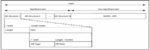
BLE Advertising packet:

Images JPEG.zip (Unzipped Files)-20210911T013840Z-001

BLE Advertising Header:

BLE Advertising Payload:

As you can see in the above images, the BLE advertising packet contains a 16-bit header and a maximum of 255 octets of payload. This means that you can transmit data up to 255 octets in the advertising packet. Out of these 255 bytes, one byte is length and another byte is AD Type. Therefore, the actual data information reduces to 253 bytes. The iBeacon uses 30 bytes of payload and the Eddystone uses up to 31 bytes of payload that depends on the type of data it sends. As the earlier Bluetooth Protocol (4 or earlier) used to allow only 31 bytes in advertising, most of the beacons have a maximum length of 31 bytes, though that’s not necessary in BLE 5.1 and beyond.

iBeacon

Now, let us take a look at the standard packet format of the iBeacon packet. The packet format is as below:

Byte 0: Length: 0x02

Byte 1:  Type:     0x01 (Flags)

Byte 2: Value:    0x06 (Typical, LE General Discoverable, BR/EDR not supported)

Byte 3: Length: 0x1a

Byte 4: Type:      0xFF (Custom Manufacturer Data)

Byte 5-6: Manufacturer ID 0x4C00

Byte 7: Subtype: 0x02     (Beacon)

Byte 8: Subtype Length: 0x15

Byte 9-24: UUID (Universal Unique Identifier)

Byte 25-26: Major Number (user defined number)

Byte 27-28: Minor Number (user defined number)

Byte 29: Tx Power in dBM@1meter (Used to calculate distance using the RSSI (Received Signal Strength Indicator))

Below is the real-time packet captured for nRF Beacon (Beacon defined for Nordic Semiconductor, not iBeacon) on the nRF Connect App. This beacon definition is the same as iBeacon, except the user defined values and flag.

Eddystone

Eddystone has three different types of protocols: Eddystone-URL, Eddystone-UID, and Eddystone-TLM.

The packet format of Eddystone-URL is as below:

Byte 0: Frame Type:       0x00

Byte 1:  Tx Power:            Calibrated at Tx power at 0 meter

Byte 2: URL Type:            0x00 for “http://www.”, 0x01 for “https://www.”,

0x02 for “http://”, 0x03 for https://

Byte 3+: Encoded URL:   The URL is provided in ASCII (American Standard Code for Information Interchange) characters, except the prefix and the last byte. These values are used for expansion or reserved for future use. Below is the expansion list:

0x00 – .com/

0x01 – .org/

0x02 – .edu/

0x03 – .net/

0x04 – .info/

0x05 – .biz/

0x06 – .gov/

The values 0x07 to 0x0d are the same as above without the /, which means 0x07 is “.com”. 0x0e to 0x20 and 0x7f to 0xff are reserved for future use.

Below is the Eddystone-URL packet captured on nRF Connect App:

The packet format of Eddystone-UID is as below:

Byte 0: Frame Type:       0x00

Byte 1:  Tx Power:            Calibrated at Tx power at 0 meter

Byte 2-11: Name Space ID: elided UUID

Byte 12-17: Instance ID: These six bytes can be assigned by the user by any method like random, sequential, or any other method.

Byte 18-19: RFU:              Reserved for future use

The packet format of Eddystone-TLM unencrypted is as below:

Byte 0:  Frame Type:      0x20

Byte 1:  Version:              0x00

Byte 2-3: VBAT:                Battery Voltage, 1mV/bit

Byte 4-5: TEMP:                Beacon Temperature

Byte 6-9: ADC_CNT:        Advertising PDU count

Byte 10-13: SEC_CNT:     Time since power-on or reboot

The packet format of Eddystone-TLM encrypted is as below:

Byte 0:  Frame Type:      0x20

Byte 1:  Version:              0x01

Byte 2-13: ETLM[0-11]: Encrypted Telemetry Data

Byte 14-15: SALT:             Encryption Salt

Byte 16-17: MIC:              Message Integrity Check

As you can see that the Eddystone TLM packet does not have the identification information within the packet, it needs to be interleaved with the identification type messages like Eddystone-URL or Eddystone-UID.

BLE Beacon Application Areas:

BLE beacons are used in different industries like retail, healthcare, entertainment, travel, and industrial automation. Below are the various usages of the beacons in different industries:

Positioning

As the beacon transmits the UUID information in a short range, a mobile application or an Operating System can easily capture this and display the location of the product/item to which the tag is attached. For example, if the tag is attached to a product which is on an assembly line, it can show the real-time location of the product in the assembly line.

The other application can be in a museum, where a beacon tag can be attached to a specific art and when the visitors come close to that particular art, the beacon sends the URL information on their mobile phones. The visitors can open the URL and get more information about the art. Another area of use can be monitoring of the visitors in the museum, where a tag is attached with each of them. So, the staff can check the number of visitors in a specific section of the museum and guide them as required.

Telemetry

The beacon tag can be fixed at any specific location and it can send varied information like the temperature, battery voltage, humidity, or any other physical parameter of interest to the mobile device/fixed receiver. For example, if the tag is attached to a fire-alarm, it can send its battery voltage information to the receiving device and schedule battery replacement.

Distance Measurement

As the beacons transmit the reference transmits signal strength value, you can calculate the approximate distance from the beacon using the RSSI at the receiver’s end.

Direction Finding

You can determine the beacon’s direction now with the introduction of location services in the BLE 5.1. You can also achieve sub-meter accuracy. This direction-finding service can be used in proximity marketing to find the point-of-interest, item finding by putting tags on personal items, asset-tracking, and indoor positioning.

Conclusion

As we can see from the above packet formats and usage, the BLE beacons are easy to implement, and they are being used in various industries. With the increase in advertising payload in BLE 5.1 and the introduction of location service, the usage of beacons will further increase. Developer can write their proprietary beacons to suite their application.

eInfochips provides Bluetooth implementation services including product development and testing for smart devices across various domains like retail, healthcare, travel, entertainment, and industrial automation. To know more about our services, please contact our experts today.


About The Author
Akhileshsingh Saithwar, works as a Member Technical Staff at eInfochips – An Arrow company.  He holds a bachelor’s degree in Electronics and Communication from Bhavnagar University, Gujarat. He has experience of working in multiple embedded domains like Avionics, Networking, Industrial Automation, and Consumer Electronics. His responsibilities include requirement gathering, validation, development, and verification in the software development life cycle.

Also read:

Certitude: Tool that can help to catch DV Environment Gaps

Digital Filters for Audio Equalizer Design

Sign Off Design Challenges at Cutting Edge Technologies


Reliability Analysis for Mission-Critical IC design

Reliability Analysis for Mission-Critical IC design
by Daniel Payne on 09-13-2021 at 10:00 am

reliability analysis min

Mission-critical IC design for segments like automotive, aerospace, defense, medical and 5G have more stringent reliability analysis requirements than consumer electronics, and entails running special simulations for the following concerns:

  • Electromigration analysis
  • IR drop analysis
  • MOS aging
  • High-sigma Monte Carlo analysis
  • Analog fault simulation

Synopsys offers PrimeSim Reliability Analysis to address these important issues.

IC Trends

Anand Thiruvengadam, from Synopsys spoke with me by Zoom last week to provide an update on their unified workflow of reliability analysis tools, which are used to shorten the time for reliability analysis. The IC design trends are pretty clear:

  • Complexity is increasing
  • Circuit size is growing
  • Frequencies creep upwards
  • Noise margins are becoming lower
  • Parasitic effects are becoming dominant
  • Higher ERC coverage is essential
  • Low DPPM required for safety
  • Power and Ground integrity are vital
  • Electro-therm reliability analysis needed

This means that IC designers need faster and higher capacity simulators to perform analysis, and that to ensure a long IC operating lifetime and comply with standards like ISO 26262, more reliability analysis is required.

Synopsys Reliability Analysis Tools

The PrimeSim Continuum tool announced earlier in the year was first blogged by Tom Simon in May, and there are four SPICE engines to choose from:

  • PrimeSim SPICE- fast and accurate for custom digital and analog/RF
  • PrimeSim HSPICE – sign-off reference for foundation IP, SI/PI
  • PrimeSim Pro – speed and capacity for DRAM and Flash
  • PrimeSim XA – FastSPICE for mixed-signal SoC and SRAM

PrimeSim Reliability Analysis is a unified workflow of proven and foundry-certified reliability analysis tools to meet the reliability challenges. To find and fix IC reliability issues early in the design process an engineer runs static analog and digital Electrical Rule Checks (ERC) using PrimeSim CCK. To design with lower margins and ensure robustness at the extremes of operating conditions , you run the Advanced Variability Analysis (AVA) tool, using ML applied to high-sigma Monte Carlo.  Power and ground integrity can be statically analyzed with PrimeSim SPRES.  Electromigration and IR drop analysis are verified with PrimeSim EMIR. Aging effects are simulated with PrimeSim MOSRA. Manufacturing test coverage and functional safety are verified with analog fault simulations using PrimeSim Custom Fault.

In the automotive market they are required to use FMEDA techniques; Failure Modes, Effect and Diagnostic Analysis. PrimeSim Custom Fault enables FMEDA, and users can even extend this by adding their own analog faults.

In the old days variability analysis was addressed with brute-force Monte Carlo analysis, but today we don’t have enough time to run a billion simulations, so by applying ML to Monte Carlo analysis we find a smarter way to get the same high-sigma coverage desired as brute force with orders of magnitude fewer Monte Carlo simulations.

Transistors change their Vt and Ids curves as a function of time, voltage and temperature, so using a tool like PrimeSim MOSRA you can now predict these effects and simulate them before tape out to mitigate the effects of aging and ensure long operating lifetimes as required by applications such as automotive.

To setup and then visualize many of these simulations there’s a tool called PrimeWave, and it provides a cohesive reliability environment with features like weakness analysis.

Synopsys Users

Tier-one semiconductor companies have already been using PrimeSim Reliability Analysis:

  • Dialog Semi – PrimeSim CCK for analog IPs
  • TDK-Micronas – Custom Fault for IP-level FMEDA analysis and ISO 26262 compliance
  • ST – EMIR analysis for analog IPs, also MOSRA, and AVA
  • AMD – PrimeSim HSPICE with AVA for high-sigma analysis

Summary

Synopsys has been in the SPICE business for decades, and with PrimeSim Continuum and PrimeSim Reliability Analysis they have productized what mission-critical IC designers clamor for, a way to find and mitigate reliability concerns.  Another strength that Synopsys has is their own IP development group, so they can use PrimeSim Reliability Analysis to produce their IP cells faster and with higher confidence across more foundry nodes.

Also Read:

Why Optimizing 3DIC Designs Calls for a New Approach

Using Machine Learning to Improve EDA Tool Flow Results

How Hyperscalers Are Changing the Ethernet Landscape


Continuous Integration of UVM Testbenches

Continuous Integration of UVM Testbenches
by Daniel Nenni on 09-13-2021 at 6:00 am

UVM Report

In recent years, one of the hot topics in chip design and verification has been continuous integration (CI). Like many innovations in hardware development, it was borrowed from software engineering and the programming world. The concept is simple: all code changes from all developers are merged back into the main development stream frequently, perhaps as often as every few hours. The program is then compiled and rebuilt to check that the changes are compatible, and a regression test suite is run to ensure that no bugs have been introduced. If the changed code contains new features, new tests for these features may be needed in the regression suite. This approach has been around for about 25 years and is adopted more every day.

This is in sharp contrast to the traditional development flow, in which programmers check out parts of the code for days and even weeks before checking it back in. Because multiple parts are evolving in parallel, they often get seriously out of sync and make integration a nightmare. CI finds incompatibilities incrementally as they pop up, making it easier to diagnose and fix any problems. Of course, programmers want to merge code that’s as clean as possible, so using an integrated development environment (IDE) with on-the-fly code checks, quick-fix suggestions, and refactoring capabilities is critical. Other types of code-checking tools such as lint, software static analysis, and security testing should also be run as part of the integration process. This whole flow should be highly automated.

Everything I just said about software is true for hardware as well. Testbenches compliant with the Universal Verification Methodology (UVM) are basically highly complex programs, and even SystemVerilog designs comprise huge amounts of RTL code. Just as with software, integration of design and verification code can be incredibly painful. I’m starting to see more EDA vendors talking about agile development and CI as a way to reduce debug effort and accelerate chip schedules. I turned to Cristian Amitroaie, CEO and co-founder of AMIQ EDA, to understand how all this works. Since AMIQ EDA is the industry leader in IDEs and lint, I figured that they must have at least a few users deploying their tools in CI flows.

Well, it turns out that there’s a whole lot going on in that area. For a start, Cristian reminded me of a press release that they issued about a year ago. It describes how the AMIQ EDA Design and Verification Tools (DVT) Eclipse IDE and Verissimo SystemVerilog Testbench Linter are used in CI flows by leading-edge companies, including Arm. Cristian said that they worked closely with users to develop this capability and to define best practice for CI. They also added new features to Verissimo to integrate tightly with bug tracking systems such as Bugzilla, project management tools, and revision control systems such as Github, Git, CVS, Subversion, and ClearCase.

For example, if the revision control system can identify which engineer changed which part of the code, Verissimo can extract this information and provide it for use in debugging build failures. I was impressed by Cristian’s description of how users can easily compare the latest changed files against those in the most recent successful testbench build and a master reference build. With CI and this level of insight into the changes, different parts of the code don’t drift far apart, and they be quickly brought into alignment when minor deviations occur.

Verissimo detects problems that would break the integration, but it catches them as soon as the code is merged so users don’t have to work backwards from testbench-level compilation errors. It’s interesting that some of the recent conversations Cristian and I have had are directly relevant to this process. The checks available include those for compliance with the latest versions of the SystemVerilog and UVM standards, including new features added and old features deprecated. Verissimo also checks for non-standard constructs supported by some EDA tools but not others, to ensure code portability across vendors. By the way, I’m focusing on the testbench since it’s so complex, but RTL code is a subset of full SystemVerilog so Verissimo and the CI flow work equally well for the design.

Cristian said that users deploying continuous integration run it automatically, in batch mode, so that checks are run as part of the merge/build/test process. When verification engineers wish to examine and fix errors detected by Verissimo, they use the advanced graphical features of DVT Eclipse IDE. Then he mentioned something that I found extremely interesting: AMIQ EDA has been running CI checks on the Github repository of the UVM reference implementation for more than a year. As a reminder, UVM consists of a standard document defining the library API and a reference SystemVerilog implementation of that library. Whenever someone changes the library, the changed code is checked within a few hours. The reports are available here. UVM development is rather quiet right now, but it will likely pick up at some point for the next revision and AMIQ EDA is already set up to contribute to that process.

It seems that this same approach could be used with other SystemVerilog and UVM design and verification IP available from public repositories. I asked Cristian about this, and he hinted that this was a future possibility. I’ll keep my eyes open and alert you all if I see wider propagation of their technology. In the meantime, it seems that AMIQ EDA has provided a solid solution to their users for applying CI to chip design and verification code. I look forward to learning more.

Also Read

What’s New with UVM and UVM Checking?

Why Would Anyone Perform Non-Standard Language Checks?

Does IDE Stand for Integrated Design Environment?


Uber, Lyft Fail their COVID-19 Test

Uber, Lyft Fail their COVID-19 Test
by Roger C. Lanctot on 09-12-2021 at 6:00 am

Uber Lyft Fail their COVID 19 Test

The COVID-19 pandemic taught many lessons and revealed various weaknesses in global supply chains and business models. The transportation industry was hit particularly hard as people stopped moving thereby taking down public transit, crashing rental car companies and airlines, and erasing the fleets of ride hailing operators.

Rental car companies and airlines were left with vehicles and airplanes with no customers, which was bad. Ride hail operators, on the other hand, lost both their customers and their drivers, which was worse.

The pandemic revealed the degree to which ride hailing operators were dependent upon profitless growth to scale their active user populations which could be leveraged for other purposes. The pandemic stripped away growth and revenue and forced a scaling back of leveraging activities such as forays into autonomous driving and trucking.

More fundamentally, though, the pandemic revealed the reality that the ride hailing business – the business of moving people in cars – was fundamentally not scalable. The metrics did not improve with the increase in the number of drivers – unless or until operators could achieve a monopolistic grip on automobile-based transportation, in which case prices could then rise after the elimination of competition – such as taxis and rental cars.

Now Uber and Lyft are frantically pivoting to food and grocery delivery, micromobility, and mobility-as-a-service (MaaS) integrations. This new positioning, which finds Uber collaborating with transit agencies and Lyft integrating robotaxis and rental cars, arrives as both companies struggle to retain drivers and passengers.

Both Uber and Lyft failed to instill confidence among customers and drivers during the pandemic. As a result, both companies saw substantial defections of both customers and drivers (including drivers succumbing to COVID) – though customers now appear to be returning more rapidly than drivers, creating an imbalance that is contributing to fare hikes likely to further undermine consumer confidence.

When the pandemic arrived, Uber and Lyft took insufficient steps to provide in-vehicle partitions to protect drivers and passengers. (Lyft made partitions available to drivers but did not require them.)

This failure was, for many drivers, the final straw in a long string of affronts from stolen tips and diminished compensation to unexplained de-activations. Pre-pandemic, Uber and Lyft – as well as competing ride hail operators around the world – had become the go-to choice for ad hoc transportation – a luxury service offered at a discount. The pandemic blasted that flimsy veneer in a flash.

The pandemic turned a discounted luxury into risky business and Uber and Lyft did little to mitigate customer and driver concern. In contrast, DiDi Xuching in China – with more active users than there are people in the U.S. – spent the millions of Yuan necessary ($15M, actually, a rounding error) to see that partitions were installed in its vehicles. This single decision preserved DiDi’s solid user base and kept its drivers committed to the platform.

DiDi recognized that the ride hailing business is not scalable in and of itself. The scaling or leveraging opportunity lies in the collective active user base and the resulting transaction activity and data insights.

Both Uber and Lyft, in fact most ride hailing operators, are seeking to become superapps. To do so, requires the creation of dedicated active user populations that can be lured into other types of transactions from public transit and micromobility to e-commerce, home loans, insurance, and other personal services.

Uber and Lyft failed to retain millions of active users and hundreds of thousands of active drivers and are now scrambling to win them back – even as the delta variant of the coronavirus threatens the building economic recovery. Worse, though, is the reality that the pandemic forced many long-term committed Uber and Lyft drivers to reconsider their employment options.

Rivals to Uber and Lyft, such as Alto in Texas and Wingz, are now gaining traction – adding drivers and passengers with superior quality of service propositions both for the passengers and for the drivers. The pandemic revealed the weakness of driver and passenger ties to Uber and Lyft, and these competitors are jumping in.

In fact, these competitors are arriving just as Uber and Lyft are feeling forced to raise their prices. If there was one thing both Uber and Lyft were good at it, pre-pandemic, it was lowering prices to eliminate competitive threats – including both competing ride hail operators and taxis. With ride hail fares on the rise, drivers and passengers are doing more shopping.

Uber and Lyft failed their COVID test. COVID revealed their poor treatment of drivers and passengers and the resulting vulnerability to competitive threats. Uber and Lyft were nimble enough to pivot away from autonomous vehicle tech and toward micromobility and transit, but not nimble enough to take care of their customers in a pandemic. Neither drivers nor passengers will soon forget and profits will continue to suffer – as reflected in the latest earnings.