
70% of today’s ASIC and SoC designs are being prototyped on FPGAs. Everybody knows that. But, did you know that automating the process of converting what could be thousands of ASIC “golden” files into FPGA-friendly versions can mean big savings in a large design?
While the basics of RTL are the same, an ASIC design containing constraints, power intent, black-box IP, cross-module references (XMRs), and other information can trip up an FPGA synthesis flow, making FPGA-based prototyping harder than it should be. On top of that, every time the ASIC design is changed, the loop of converting the design for the FPGA prototyping platform repeats, with all the existing conversion problems plus new ones.
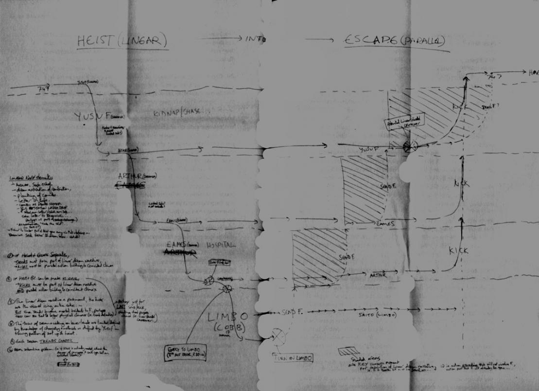
 the timeline for Inception, as drawn by writer/director Christopher Nolan
While avoiding conversion altogether probably isn’t feasible, what is in the realm of possibility is creating a reproducible, scripted process for conversion that can automate the process. Design environments obviously differ in some of their specifics, but a new white paper from Angela Sutton at Synopsys outlines the areas designers should concentrate on to smooth out the flow.
The first problem in conversion is an ASIC design is rarely one big file; instead, it is usually thousands of source files in some type of hierarchical directory structure. The ability to deal with Verilog libraries and file name extensions, along with search paths specifying include directories, means the FPGA synthesis tool can get the entire design from its pieces. Some massaging may be required to ensure files are found.
Issues then turn to technological differences, starting with memory implementation. An ASIC design may easily overwhelm block memory resources in an FPGA. External memory implemented somewhere on the FPGA-prototyping platform may need to be synchronized, or a distributed RAM approach taken where registers are used. Somehow, the mapping needs to be created to tell the FPGA synthesis tool what to do.
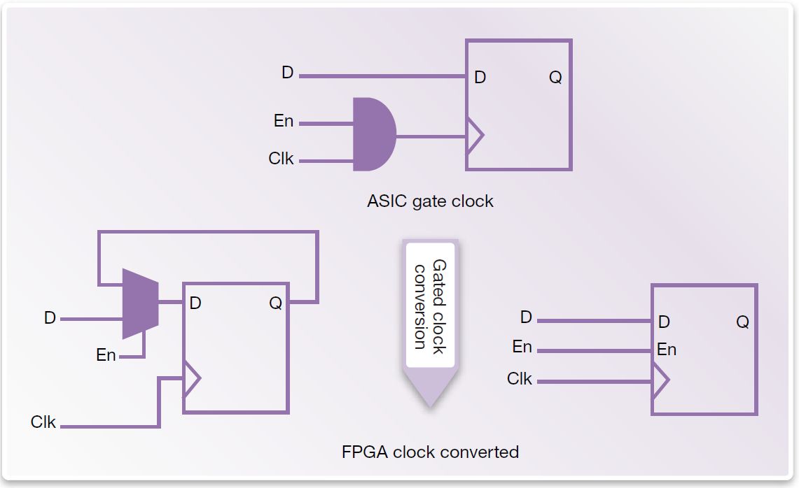
Clock trees also present some major differences, where an ASIC design can be mismatched to the limited number of clock domains available in an FPGA. Most FPGA synthesis tools can run a clock report, examining generated and gated clocks and other clocks that may present problems. Tcl-based scripts can be applied to automatically edit netlists, replacing constructs with more FPGA-friendly implementations.
Power domains are also an area where FPGA and ASIC designs can differ. ASICs may contain definitions using Unified Power Format (UPF), calling out power domains, isolation cells, and retention circuitry that may or may not have equivalency in the FPGA implementation. One thing to keep in mind is the value of validating power behavior in the prototype, so designers should be careful to not just ignore these definitions.
There is also a lot to be learned and captured from the FPGA synthesis process itself, beyond just the partitioning effort where a design is laid down across multiple FPGAs which we talk about a lot elsewhere in SemiWiki. Once performance improvements are found – reducing high fanout nets, removing asynchronous resets on multipliers, isolating critical paths inside a block, and other items – they can be flagged for repeatable synthesis.
For more on the process and items to look for, here’s a link to the full white paper:
My RTL is an Alien! Accelerating and Automating ASIC to FPGA-Based Prototype Conversion
Again, your mileage may vary depending on your synthesis environment and attributes of the FPGA prototyping platform used. However, the thought process involved – making use of Tcl scripts, ifdef directives, and other automated techniques – can make the conversion from a complex ASIC design to an FPGA-friendly design faster and repeatable.
The whole idea of an FPGA prototyping platform is to spot issues, provide feedback, and help ASIC designers iterate and solve problems before committing to silicon, right? Don’t view it as a one time undertaking, but find ways to streamline and automate the conversion.
lang: en_US


Comments
0 Replies to “Stick to the script for repeatable FPGA-based prototyping”
You must register or log in to view/post comments.