With the increasing complexity and diversity of the mechanical constraints and electrical requirements in electronic product development, printed circuit board designers are faced with a number of difficult challenges:
- generating accurate (S-parameter) simulation models for critical interface elements of the design – i.e., connectors sockets, (twisted-pair) cables
- developing comprehensive simulation/analysis models for entire packaging solutions – e.g., rigid-flex board topologies
- accelerating the design optimization-analysis feedback loop
Given the aggressive schedules allocated to PCB development, typically dependent upon completion of key IP/SoC/module design milestones, the last challenge above is especially critical. The evaluation of interface compliance measures – e.g., timing/voltage margins, eye diagrams, bit error rate estimates – may necessitate board design updates, which then need to be re-analyzed. Minimizing the time and engineering resource (and the risk of an error) to close on implementation-extraction-analysis iterations is crucial.
I had the opportunity to chat with Brad Griffin, Product Manager Group Director at Cadence, about these challenges, and some of the features incorporated in the recent Sigrity 2018 release that will significantly alleviate them.
Brad indicated, “Bridging the gap between the mechanical model of interface components and the corresponding electrical model for power integrity and signal integrity simulation is a key addition to this latest release. The Sigrity 3D Workbench takes the physical Allegro board model as input, and applies full-wave field solver technology to derive the S-parameter model for simulation.”
The examples below illustrate the mechanical model of board-mount connector pins, which would be presented to 3D Workbench for S-parameter model generation. (The “breakout” of the board trace is included in the full-wave field solver input, to the point where a 2D hybrid solver analysis of the PCB trace can be applied.) The physical models of cables, connectors, and sockets are also analyzed by 3D Workbench.
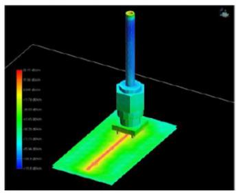
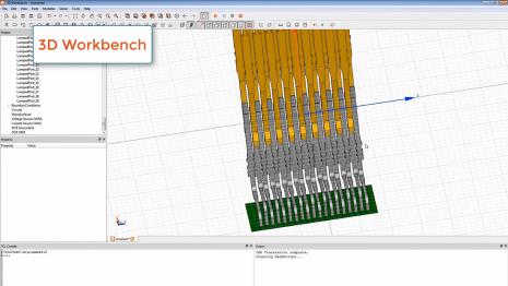
An illustration of how 3D Workbench is used in a larger flow is depicted below. Brad said,“This 3D Workbench capability is a new component of existing flows, such as the Serial Link Compliance validation solution shown in the figure.”
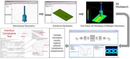
Brad continued, “Our internal IP group develops high-speed SerDes and parallel interface (DDRx) offerings, verified to the compliance measurements associated with industry standards. The Allegro and Sigrity teams collaborated closely with the IP group on the functionality and testing of 3D Workbench and the Sigrity 2018 release.”
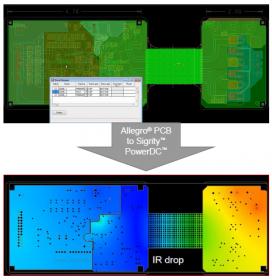
With regards to the growing utilization of rigid-flex technology, Brad noted, “There is a comprehensive connection between the rigid-flex design and analysis flows. Allegro is integrated with the extraction and simulation features of Sigrity PI/SI. Again, a mix of full-wave models(from 3D Workbench)and 2D hybrid solver models can be extracted, stitched, and simulated.”
The figure below illustrates a rigid-flex design with the corresponding visualization of the Sigrity PowerDC results. (Note the power distribution in the flex cable to the mezzanine card on the right results in significant losses.)
Speaking of the integration between Allegro and Sigrity, Brad was excited about the productivity gains this enables. SI/PI engineers can make their design changes in the Sigrity environment, re-extract and simulate – e.g., a specific via array pattern optimized to meet loss targets. Brad highlighted, “A key feature in this release is that updates made in the Sigrity platform are directly incorporated into the Allegro model, without the need to re-draw.”

The handoff of “markup” requests from the SI engineer to the physical design team is eliminated, improving the rate of design closure (and reducing errors) in the final optimization phase before release for PCB fabrication.
Future Challenges
I asked Brad about upcoming challenges for PCB (and rigid-flex) designers.
“I’ll point out two of the areas we’re working on.”, Brad said. “In the future, support will be provided to work with encrypted mechanical component models, for improved security of the component vendor’s intellectual property.”
“And, with the growing complexity of board designs, combined with the higher datarate defined for future interface IP standards, full wave model accuracy(out to multiple harmonics of the fundamental)will be required for a larger set of models. Full-wave mesh topologies will be denser, requiring greater compute resources. The methodology leveraging both full-wave and hybrid solvers for extraction and simulation will be distributed across multiple machines.”
The 3D model generation capabilities, the support for full system model PI/SI analysis with the combination of solvers (including intricate rigid-flex topologies), and the focus on improving the PCB design-analysis optimization loop are all part of the enhancements in the recent Sigrity 2018 release (link).
-chipguy
Share this post via:


Comments
There are no comments yet.
You must register or log in to view/post comments.