James Clerk Maxwell’s eponymous equations are the basis for simulating electromagnetic wave propagation. In school, EE majors tended to fall into two camps: (a) those that thoroughly enjoyed their fields and waves classes, who liked doing surface integrals, and who were adept at demonstrating the “right hand rule”, and (b) those that took the required courses but quickly focused on other disciplines within the expansive breadth of the electrical engineering field.
At the recent DesignCon 2016 conference, Brad Brim, Product Engineering Architect at Cadence’s Sigrity group, gave an enlightening presentation that focused on bridging the gap between these two groups, entitled: Access to 3D EM Simulation — for those who care and those who couldn’t care less.
Brad began with a brief history of 3D EM simulation technology — from the solver algorithms used, to the simplifying material and model assumptions of Maxwell’s wave propagation theory that enable the speedups of static and quasi-static modes. The figure below summarizes this chronology.
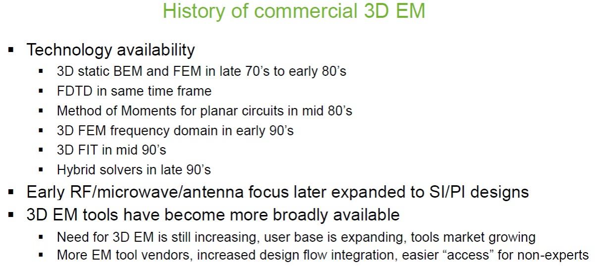
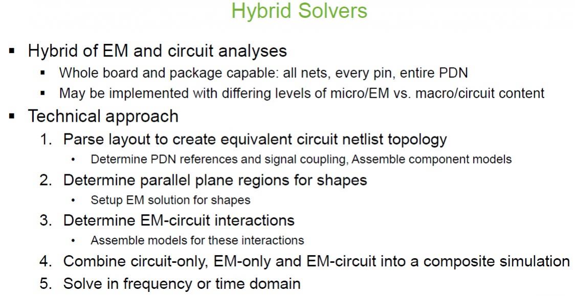
Specifically for the DesignCon audience, Brad highlighted how EM simulation has evolved from the domain of RF antenna design to become a fundamental tool in the analysis of package and PCB designs. A complete “hybrid” system analysis approach combining EM and circuit simulation models was emphasized, whether for the voltage/timing margin “eye diagram“ analysis of signal interfaces (SI) or comprehensive power distribution network analysis (PI).
Yet, how does an engineering organization bridge the knowledge gap highlighted above, between EM experts and the (much larger) design teams that need the EM simulation results?
Brad presented his vision for the methodology to enable design teams to have access to the simulation technology required for analysis of a complex system model. The approach has two fundamental tenets:
- The EM experts and the package/PCB designers need to work from a common physical layout database.
Although this may seem obvious, it is not uncommon for an EM expert to prepare a model independently, in a separate tool environment. Material stack-ups, via arrays, representative trace topology, power distribution planes, etc., are uniquely drawn and analyzed, and offered to the design community at large as design constraints (to verify in a constraint checker) and/or as recommended design library cells.
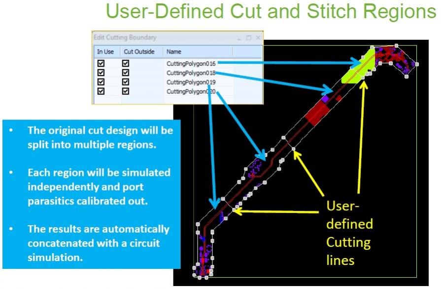
- The approach to generating detailed EM simulation S-parameter results initially utilizes the EM expert to define the geometric “cut points” in the design. Then, with this initial setup, the design team can directly launch EM simulation, and thus, more efficiently iterate on model analysis, minimizing the resource demand on the EM expert.
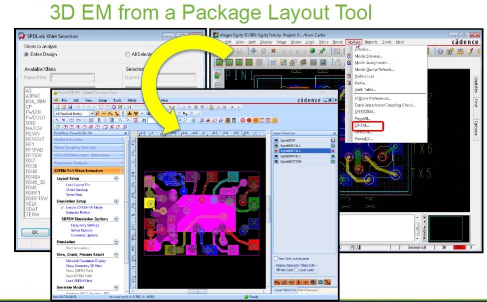
These cuts define the “ports” for EM simulation and S-parameter model generation. Individual models are then stitched together as part of the system model. The figures below illustrate how a cut-and-stitch model definition is created, and an example of how EM simulation would be invoked directly from within the Cadence Allegro Sigrity environment.
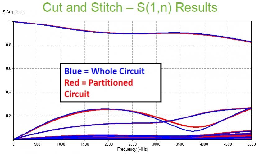
Is the “cut-and-stitch” method for model generation sufficiently accurate?
Brad presented several examples demonstrating the accuracy of the overall system results and the speedup relative to attempting a single EM model analysis (which would be infeasible on large designs, regardless). The figure below shows an example of the S(1,n) set of model S-parameters for the cut-and-stitch approach, compared to an analysis of a full model.
EM simulation technology must become more accessible to a wider cross-section of the design community. The insights of EM experts are used to assist with model and simulation setup, yet the analysis results and optimization decisions are most efficiently led by the design teams. A common physical database accessible to all is a prerequisite.
The Cadence Sigrity team is enabling this trend, with a defined methodology for model partitioning and simulation, all within their tool platform. As Brad succinctly summarized the Sigrity approach toward enabling EM simulation for design teams, “It’s time to put the A back in EDA.”😀
More information on the Cadence Sigrity “cut-and-stitch” EM simulation methodology is available HERE.
-chipguy
Share this post via:


Comments
0 Replies to “Expanding 3D EM Simulation Access to All”
You must register or log in to view/post comments.