At the recent DesignCon 2020 in Santa Clara, Cadence introduced a new product, Sigrity Aurora. You won’t find a press release about this announcement. Rather, Brad Griffin, product management group director at Cadence, presented Sigrity Aurora in the theater at the Cadence booth. This one caught my eye and deserves some discussion. DesignCon has become a system-oriented event. Think chip, package, PC board and chassis. This breadth of problem-solving has created a large and very diverse show floor and technical program. Relevant, real-world system design challenges are treated here. If you missed it, I highly recommend catching DesignCon next year.
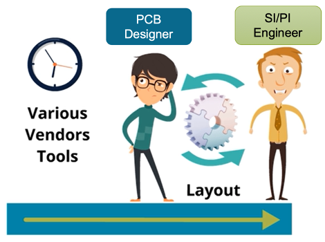
Sigrity Aurora is a product that addresses the signal and power integrity (SI/PI)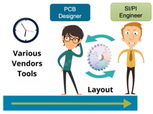 challenges associated with high-performance PCB design. The question posed by Brad in his presentation was quite simple – how many times do you iterate between design and analysis in a PC board design? That is, iteration between the PCB designer and SI/PI engineer? I can tell you from first-hand experience this kind of back-and-forth can waste a lot of time. If you’re not careful, you tie up a very valuable and scarce resource, the SI/PI expert.
The disparate expertise of a PCB designer and an SI/PI engineer contribute to the challenges here. So does a disparate tool flow with lots of conversions and mapping. In his theater presentation, Brad posed a way to address all these issues. What if you had a single vendor solution that could address: schematics, re-route signal and power integrity (SI/PI) analysis, placement, routing, in-design SI/PI analysis and final signoff?
It turns out Cadence has the product breadth to offer such a solution, and that was the essence of the announcement. Thanks to their Sigrity product line, Cadence has an extensive set of analysis engines to address tasks such as screening technology (impedance and coupling checks), return path checking, SI analysis (reflection and crosstalk) and PI analysis (IR drop).
And thanks to the new Sigrity Topology Explorer, pre-route and signal net extraction can be one to support what-if analysis.
The punchline of Brad’s presentation was that all of this capability can now be delivered through the popular Cadence Allegro PCB editing and routing technologies with Sigrity Aurora, which can read and write directly to the Allegro PCB database. A powerful set of analysis engines with a tight and efficient integration to a familiar implementation flow. The applications of such a tool are diverse and significant. A few scenarios were illustrated in Brad’s presentation as follows.
Screening technology for electrical rules checks (no models required)
Impedance analysis screening:
- Same requirements on stack-up
- Global view of results more accessible
- Look for outliers
Coupling analysis screening:
- No SI model required
- Electrical coupling is more accurate than geometrical methods
- Global view of results
Return path screening:
- Report nets with possible return path problems
- Use a figure of merit such as return path quality factor
- Return path visualization
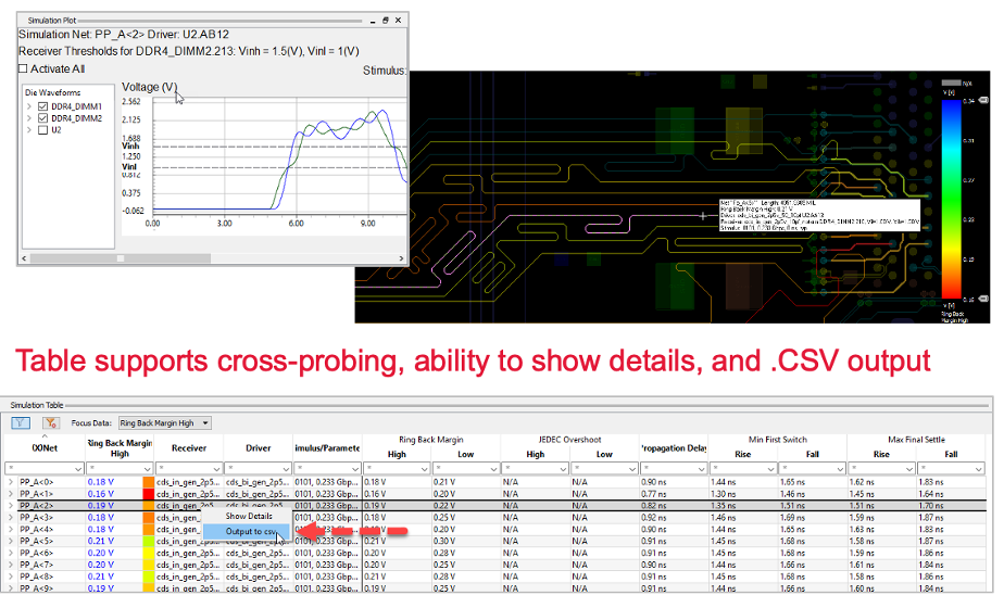
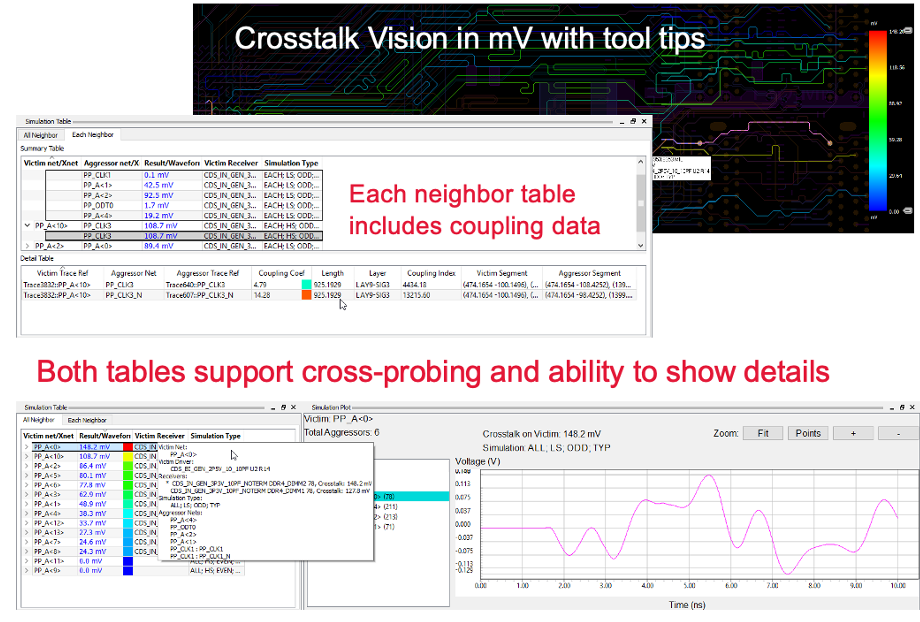
Signal integrity technology (driven by industry-standard IBIS models)
Reflection analysis output:
Crosstalk analysis output:
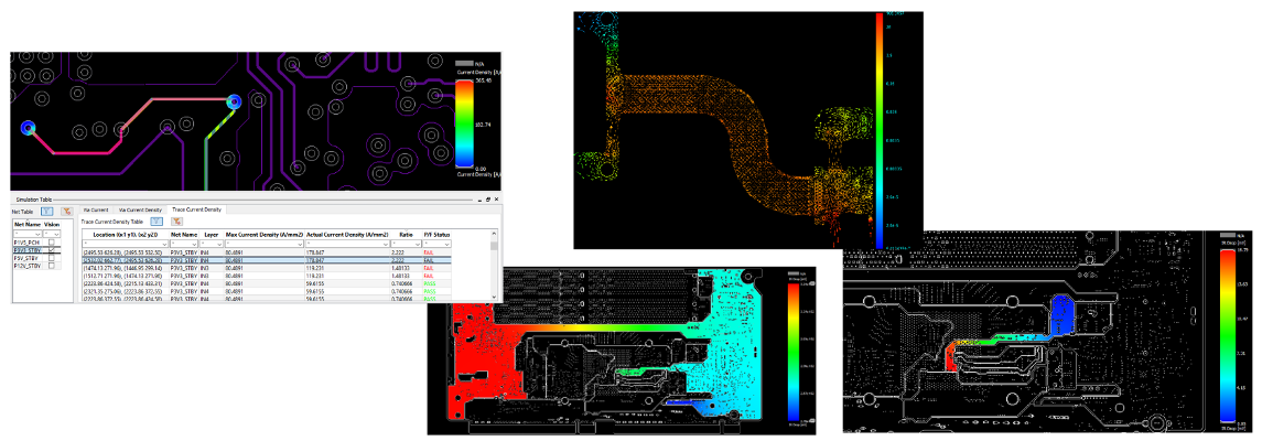
Power integrity technology (driven by Allegro PowerTree technology)
IR drop analysis output (IR drop vision can be displayed as voltage, IR drop, or current density):
And pulling it all together, system-level simulation for signoff
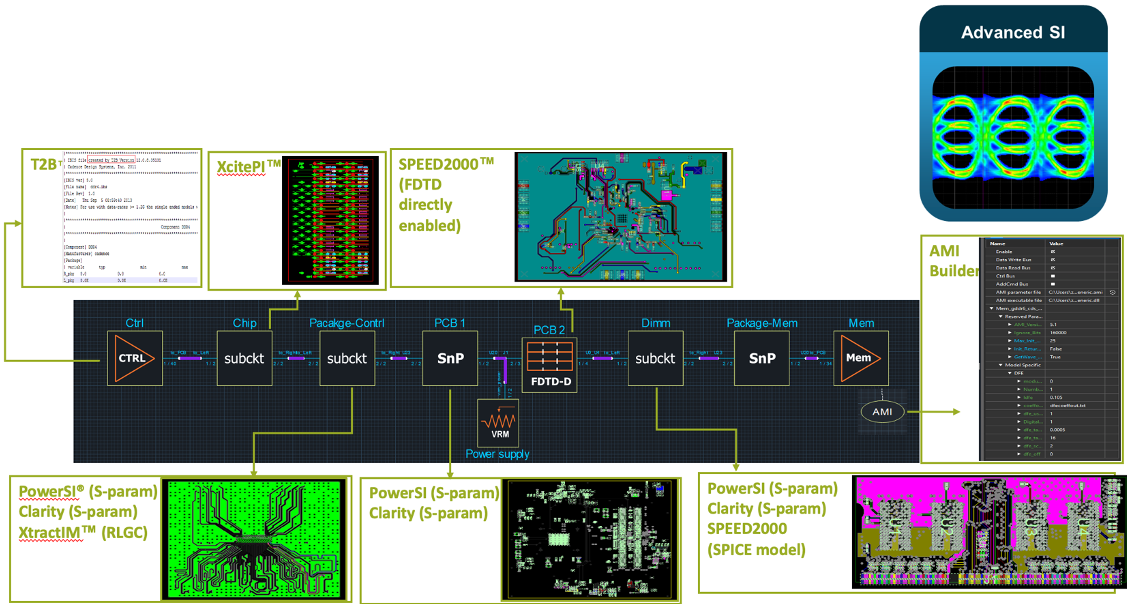
If you’re engaged in high-performance PCB design, this comprehensive design flow is definitely worth a look.
Share this post via:


Comments
2 Replies to “Bridging the Gap Between Design and Analysis”
You must register or log in to view/post comments.