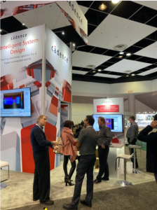
This year is the 25th anniversary for DesignCon. The show has changed a lot over the years. Today, it’s a vibrant showcase of all aspects of advanced product design – from ICs to boards to systems. The show floor reflects the diverse ecosystem. If you missed it this year, definitely plan to go next year.

The DesignCon technical program has many tracks. Some discuss theoretical research while others focus on real design issues being faced today. I attended a very interesting presentation that falls in this latter category. Danny Ho, SI/PI department manager at MediaTek discussed 2.5D design. There are many presentations at DesignCon on this topic. This one was different. Danny began with an overview of the motivation for 2.5D packaging vs. more traditional approaches such as flip-chip and discussed the need for a silicon interposer to support designs containing HBM memory stacks.

This was not the focus of his talk, however. Rather, Danny focused on the signal channel created by the silicon interposer. The associated microbumps, C4 bumps, TSVs and dense routing create structures that are significantly more complex that what’s seen in a flip-chip package. It turns out there are many technical challenges associated with these structures, and Danny’s presentation explored several of them. The work presented was a collaboration with Cadence Design Systems. Cadence sponsored the session.
From an electrical perspective, there will be signal integrity challenges such as dense coupling and reflection effects. The TSVs also present different characteristics than has been seen with more traditional packaging. The tight die-to-die tolerances will also present EMI challenges.
The large size of the silicon interposer and the associated high-power consumption of the on-board components will also present warpage and heat dissipation issues.
In the study presented, the signal integrity issues associated with coupling and reflection were investigated. The performance levels of interest extend to those delivered by 50G – 112G SerDes technology. This presents a complex modeling problem. Traditional tools cannot deliver the required accuracy in reasonable time. Cadence Clarity 3D Solver was chosen to perform the analysis. Danny explained that Cadence Clarity can accommodate the complex models associated with the silicon interposer channel and employ massive parallel compute power to perform the analysis. According the Danny, this capability was previously unavailable.
Danny then discussed some real case studies and what was learned. A key issue is alignment of the larger C4 bumps on the interposer and the microbumps on the chip. Due to the potential incompatibility of chip design constraints and foundry interposer design rules, one can have the same or different pitch relative to these two structures. Misalignment of these structures can cause reflection and coupling. Specifically, crosstalk issues are seen with mis-aligned C4/microbump structures.
Next, the effects of copper dummy metal were discussed. All foundries have rules regarding metal uniformity and dummy metal must be added to adhere to these rules. Using Cadence Clarity, it was found that insertion loss degradation was not a major issue below 5GHz due to dummy metal. Above 5GHz, insertion loss and return loss become much worse with dummy metal however since the dummy metal increases trace impedance and capacitance.
Another experiment consisted of re-arranging the microbumps to improve alignment. This improves crosstalk. Return loss and insertion loss still showed some degradation. A final experiment looked at the effects of ground plane shielding. It was found that insertion loss and return loss improved when ground plane shielding was removed.
This work provides a lot of guidance for effective interpose design. Re-arrangement of microbumps for better alignment provides improved performance. This requires careful design modifications, however. Now that data is available, Danny reported that there is now discussions with foundries regarding dummy fill and ground planes and their effect on design performance.
Share this post via:


Comments
There are no comments yet.
You must register or log in to view/post comments.