
Co-simulation, two or more simulations running concurrently in some manner, is not a new idea. I have written before about multiphysics systems able to model thermal, stress, CFD and other factors simultaneously. I just read a white paper from Siemens based on a different method, using an open standard called the Functional Mockup Interface (FMI) to connect simulators/models to co-analyze mechatronic and other systems across a range of multidiscipline analyses, going beyond what I have seen in multiphysics systems. My take is that looks like a more total systems-centric view to multi-domain simulation than chip-centric approaches.
About FMI
FMI is a standard created within the Modelica Association, an organization founded in 2000 in Sweden, with the intention to simplify the creation, storage, exchange and (re-) use of dynamic system models of different simulation systems for abstract model (e.g. MatLab)/software/hardware-in-the-loop simulation, for cyber physical systems, and other applications. The list of FMI members is impressive: Bosch, Dassault, Siemens, Synopsys/Ansys, Ampere, Saab, Airbus, Caterpillar, Hyundai, GM, Boeing, NVIDIA, VW, Volvo, MathWorks, Maplesoft and many more.
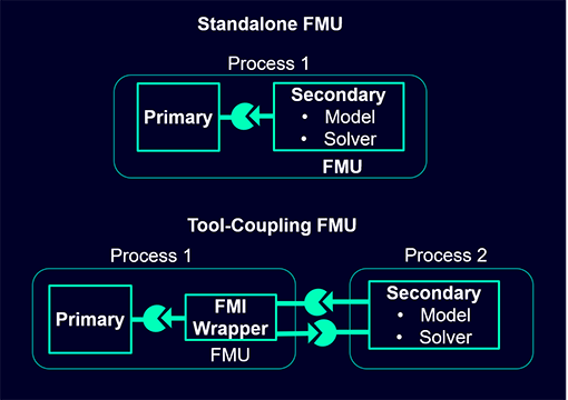
There are two use-cases: standalone FMUs and tool-coupling FMUs. The standalone approach allows a component provider to build an abstracted model of an IP based on simulations within a specific domain. A system builder can then use such a model in their system analysis without revealing implementation details and without need for licenses used in building that abstracted model. A tool-coupling model provides more flexibility through FMI defined API interfacing between simultaneously running simulators. Both methods depend on a user-defined time-step to determine communication frequency.
Which approach will be most effective will depend on the application. The Siemens white paper provides examples for both use-cases.
A mechatronic application
The paper illustrates with three applications. The first of these is a mechatronic example for which the electrical side is a circuit to control a stepper motor. This circuitry is modeled in HyperLynx AMS which is FMI compatible. The mechanical part connects the motor output to a gear reducer, then a winch, raising or lowering a weight suspended on a rope. I’m guessing this is not a typical application, more likely an artificial use case to illustrate a capability without revealing customer proprietary details in real designs. The mechanical part is modeled in Siemens Simcenter Amesim. Sensors feedback winch RPMs and the airgap between the weight and the ground.
This method uses a tool-coupling FMU, here by generating an FMU model for the circuitry which can be inserted into the Amesim mechanical model. Remember in tool-coupling cases this model is an interface between the mechanical simulation and the electrical simulation, both of which will be running.
The paper illustrates the point of running this joint simulation in first observing that the rotational velocity of the gear shift is noisy and the weight hits the ground after a few cycles. They replace the stepper motor with a stronger model and reduce the weight, following which simulations show much cleaner behavior and the weight doesn’t hit the ground. Here and in the standalone methods users will need to experiment with time-step choices to find an optimum balance between accuracy and analysis throughput.
A control system application
The white paper illustrates a standalone FMU example with a power convertor example. The controller is designed through Altair Twin-Activate and MathWorks and exported as a standalone FMU. This is then imported into HyperLynx AMS to model the power convertor electronics around the controller. HyperLynx can run simulations with this FMU model without need for co-simulation. Again, a user may need to fine-tune a time-step choice for optimum results.
Very interesting to see a method for handling multi-domain simulations outside conventional multiphysics applications. I can see why this would be popular with system builders who have preferred simulator choices in each domain yet need to be able to stitch them together for full-system analysis. You can download the whitepaper HERE.
Also Read:
Siemens U2U 3D IC Design and Verification Panel
Solving the EDA tool fragmentation crisis
Complex PCB signoff challenges
Share this post via:


Comments
There are no comments yet.
You must register or log in to view/post comments.