The meaning of the word “Veloce” is “blazing fast”. It is the inspiration behind the name of the Ansys VeloceRF electromagnetic (EM) passive device synthesis platform that has been a favorite among RF and high-speed integrated circuit (IC) designers for more than 15 years. VeloceRF is a name that designers automatically connect with speed. Inductors are very often used in analog, RF, and high-speed integrated circuits for tuning, impedance matching, filtering, ESD protection, etc. Wireless and IoT devices, such as cellphones, tablets, laptops, wearables, mobile communications equipment, and automotive radars are powered by analog and RF ICs that rely on several inductors to operate. On-chip inductors generally enhance the reliability and efficiency of integrated circuits; they can offer circuit solutions with superior performance and contribute to a higher level of integration.
The primary capabilities sought by chip design engineers are speed and performance, and these are the key features of VeloceRF. The software offers an easy interface, with unparalleled speed and performance in synthesizing and modeling passive devices. In the IC design world, defining speed and performance can be very subjective. In the VeloceRF tool, designers place down, in layout, a variety of passive electromagnetic (EM) structures that are DRC-clean and manipulate the devices in the form of parametric cells that can be used to quickly generate an accurate EM model. VeloceRF leverages the Ansys RaptorX EM solver, which is known for its accuracy, and high capacity, and has been certified by all major foundries on multiple fabrication processes. So, for VeloceRF, the performance is a given but what about the speed?
Fortunately, the RaptorX EM engine has unrivaled speed, but for a designer, speed is not as simple as having the fastest extraction or simulation times. Speed is a wholistic measure, it is a metric that precisely measures how effectively the tool allows them to adhere to their timelines and be the pioneers in the market. No other tool in the industry comes anywhere close to maximizing a designer’s efficiency than the Magic Wand passive device synthesis feature of VeloceRF, and this is where the fun really begins.
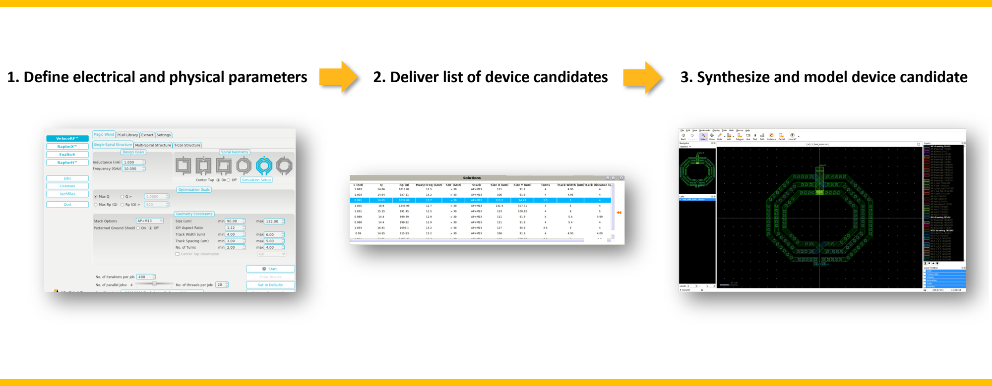
Magic Wand is a powerful feature of VeloceRF that allows designers to easily select the type of EM structure that they need to synthesize together with the respective set of physical constraints, design goals, and EM extraction settings. When ready, Magic Wand will start running EM extractions in the background (with the RaptorX EM engine) that are optimized around their constraints and design goals. The end result is an entire library of parametric cell solutions the designer can immediately begin to use and analyze. Figure 1 displays an example of the Magic Wand user interface, a set of optimized solutions, and a parametric cell placed in the layout. The flexibility provided by this feature is unprecedented. Designers have some control over how strenuously the Magic Wand optimization engine looks for solutions that can be used as soon as they are found. This means real work can begin immediately while the optimization continues to run in the background. The designer can either let Magic Wand finish running extractions to completion or stop the run. Either way, the solutions are automatically saved and can easily be recalled in the future.

One of the biggest bottlenecks in design efficiency is falling into the trap of redundant and iterative methodologies. How well can the measure of speed be served if the starting point for synthesis isn’t even based on a real electromagnetic extraction? The user takes a big step back if they start with a ballpark estimate just to realize after the fact, they still need to verify the performance of the device by running an electromagnetic extraction and simulating it. This is where Magic Wand really hits the mark in speed and efficiency. Since the solutions are inherently found with RaptorX electromagnetic extraction, they are fully ready to go and verified right out of the gate. If the user decides to make modifications to the parametric cell, the changes can quickly be analyzed in VeloceRF with a built-in performance plotting utility.
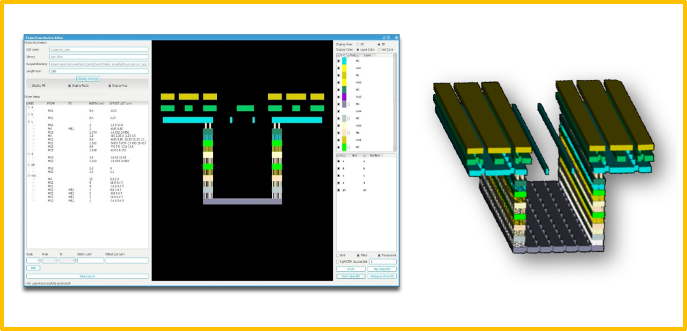
VeloceRF can easily synthesize a wide range of passive structures, which includes a variety of single-ended and differential inductors, multi-spiral transformers, T-coils, and transmission lines. One of the newest features of VeloceRF is the Bus Builder. Rather than relying on predefined transmission line topologies and spending weeks to design custom buses for clock and signal propagation according to increasingly demanding design constraints, this feature enables customized design and modeling of complex busses tailored to specific user settings, including an arbitrary number of lines, metal layers, flexible geometries of the ground net, and dummy fill. Figure 2 shows the Bus Builder interface with cross-sectional and 3D views.

The feature-rich aspects of VeloceRF, combined with its speed and comprehensive device synthesis portfolio, allow for a broad spectrum of enjoyable user experiences. Regardless of which design synthesis paths are taken, there are assurances and features shared for all of them. Whether or not an EM structure is synthesized with Magic Wand, placed directly from the Parametric Cell Library, or bus lines are designed with the Bus Builder, it will have automated support for ground shields and dummy fill and assured to be DRC clean. VeloceRF is also fully integrated with the Cadence and Synopsys custom IC design platforms and provides a variety of plug-and-play features that enable designers to seamlessly utilize the synthesized parametric cells and EM models with their simulation flows.
One of the more advanced features of VeloceRF is the full coverage of layout dependent effects (LDE). These effects include impacts such as horizontal metal widths and spacing, dielectric damage, metal thickness, and side and bottom dielectric variations. Properly modeling LDE is already a critical design trend in the industry, especially for advanced technology nodes from 7nm down to 3nm. The fact that the RaptorX solver is the only electromagnetic engine in the industry to boast this capability and be fully certified by TSMC down to 5nm with more to come soon, makes VeloceRF a clear standout from the competition. Advanced dummy fill and complex ground shields are a necessary evil for EM solvers to deal with in terms of prolonging extraction times and limiting accuracy, but the performance of VeloceRF truly makes these challenges seem like an afterthought.
VeloceRF is a powerful platform that will take any IC design team in need of passive EM structures to the next level of success. Whether success is measured by more first-pass silicon, faster time to market, cost savings, risk aversion or good old-fashioned engineering entertainment for an IC designer, VeloceRF can provide it all when it comes to passive device synthesis. Its robust feature set with Magic Wand, Bus Builder, Parametric Cell Library, and Performance Plotter provides a broad spectrum of design flexibility while leveraging the RaptorX EM solver’s best-in-class performance, speed, and capacity attributes. Trends in the semiconductor industry are fast-paced and ever-changing, and it is more important than ever that design tools like VeloceRF reflect that. As design groups that require EM modeling begin to entrench themselves in advanced technology nodes, having a tool at their disposal that can capture LDE and be fully certified by leading foundries will be an unrivaled game-changer in the industry.
VeloceRF captures the essence of a famous quote from George S. Patton and his mentality for success, “Don’t tell people how to do things, tell them what to do and let them surprise you with their results.” Executing a plan quickly and efficiently is far more important than waiting for the perfect plan and being slowed down by analysis paralysis. The speed and optimization attributes of VeloceRF allow plans to be executed as fast as possible while ensuring the user is in the correct design space. Critical time and engineering resources are not wasted upfront due to a designer dwelling on how to micromanage the tool and synthesis settings and how the devices will be modeled later on. One thing is guaranteed: VeloceRF will always impress with its results.
Also Read:
Simulation World 2024 Virtual Event Simulation
2024 Outlook with John Lee, VP and GM Electronics, Semiconductor and Optics Business Unit at Ansys
Unleash the Power: NVIDIA GPUs, Ansys
Share this post via:


Comments
There are no comments yet.
You must register or log in to view/post comments.