RVN! 26 Banner revised (800 x 100 px) (600 x 100 px)

SoC Design Management with Git

SoC Design Management with Git
by Daniel Payne on 02-21-2018 at 12:00 pm

Linux creator Linus Torvalds lives in Oregon not too far from me and he also created the popular Git system for Design Management (DM) in 2004 that is now used by many software developers. So what makes Git so attractive as a DM tool?

  • Feature-branch workflow
  • Easy to switch context between features
  • New features can be created orderly and be traceable
  • Low overhead for making releases
  • Speedy performance
  • Distributed DM system
  • Active user community

Would an SoC design team use Git as their only DM tool? Probably not, for several good reasons like:

  • Git is designed to control text files, not binary files
  • All versions of all files are kept by each team member
  • Incremental changes to binary files are not exploited

As an example, consider making 10 versions of a text file and also a binary file, then look at how many MB of data storage are required for each in a DM system:

You really don’t want to use Git for versioning binary files that are part of your SoC designs because Github has a recommendation that repository size stay under 1Gb, while each file size is limited to 100MB in order to keep performance levels acceptable. Sure, you could use multiple repositories in Git to get around these limitations, and even use some Git add-ons to work with larger binary files.

Another direction to consider for versioning binary files is with Perforce, because that tool allows you to have a workspace with single versions of each file, plus just the required portions of the repository.

The Percipient Approach

Thankfully, we have a vendor like Methodics that has figured out how to enable DM for SoCs that have both text and binary files, and their tool is called Percipient. The main features of Percipient include:

  • A single source of truth
  • Designs decomposed into units and subunits, or IPs
  • Each IP can be saved in a variety of DM systems (Git, Perforce, Subversion)
  • Each user can have a workspace with the entire design or just pieces of the design

Here’s a diagram to show how all of your SoC data can be managed, organized and versioned with Percipient and other DM tools:

So with this flow you have all of these IPs and they can be released, creating new versions. Your IP becomes qualified to some level, and all of that is published automatically to the Percipient platform. Users just query Percipient to find the new versions of any IP that they need. Each qualification level along with meta data are kept in the system.

As a bug is discovered in a version of an IP then you just file a ticket about it using your favorite bug-tracking system, while users of Percipient can view all bug reports for that IP. All the info needed about any IP is visible to all team members, across the globe, in real time.

Because Percipient uses a single source of truth approach it becomes the one place to go to when asking a question about design readiness. Users can even add simulation and test results to any IP, and you can find out if each IP has met specification compliance using IP properties. There’s even an integration with Jama, so that users can track IP requirements throughout the design lifecycle.

Percipient, Perforce and Git all work together because Percipient supports the Git-P4 type IP, which is using the Perforce Helix4Git feature. Perforce is quite efficient as it host the native Git data, giving users the ability to clone any portion of data from any branch. So Git-based developers continue working in their favorite tool, then others can populate the same data, so you’re not having to populate an entire Git repository.

Summary

Methodics has learned how to best manage complex SoC design projects by integrating with other popular tools like Git and Perforce. Every team member with Percipient can get the right IP version into their design and be alerted of any changes or bugs filed against that IP.

Read the complete White Paper from Methodics here.

Related Blogs


SPIE 2018 Mentor Graphics Scott Jones and SemiWiki

SPIE 2018 Mentor Graphics Scott Jones and SemiWiki
by Daniel Nenni on 02-21-2018 at 7:00 am

Next week is SPIE, the leading lithography networking event here in Silicon Valley. Scott Jones is not only attending but also presenting at the 15th Annual LithoVision on Sunday. I will be at SPIE as well so if you want to meet up let us know. We will publish a blog on Scott’s presentation the morning of for those who cannot attend. Walking around SPIE with Scott is like walking with me at DAC, everybody knows him and wants a word or two. For the past 10 years EUV has always been a hot topic and this year will be no different since we are actually getting close to production quality EUV, absolutely.

The evolving semiconductor technology landscape and what it means for lithography Scotten W. Jones, IC Knowledge LLC
The semiconductor industry is approaching fundamental physical limits on traditional scaling. This has led to major changes in devices architectures with more changes on the horizon. 2D NAND, long the driver of leading edge lithography is transitioning to 3D NAND. In 3D NAND lithography linewidths are relaxed and scaling is accomplished by adding layers. In the leading-edge logic space, planar transistors have given way to FinFETs with stacked horizontal nanosheets on the horizon. Longer term complimentary FETs with stacks of n and p nanosheets may also lead to relaxed linewidths and scaling by adding layers. In the DRAM space a fundamental tradeoff between capacitor k values and leakage has slowed scaling with no long-term solution currently available.

In this paper I will discuss the technology transitions in each of these three-key application areas and the impact on the number of lithography layers and types of exposures required.

While Scott attends sessions I will be hanging out with the Mentor experts (booth #222) who are featured throughout the conference. Mentor Graphics, a Siemens Business, of course are EDA lithography royalty and will be showcasing EUV readiness and a new OPC approach for handling memory applications & flows. Papers relevant to those focus areas are listed below and here is the Mentor at SPIE landing page:

EUV Readiness

  • SRAF requirements, relevance, and impact on EUV lithography for next-generation beyond 7nm node
  • Model-based hyper-NA anamorphic EUV OPC
  • Impact of aberrations in EUV lithography: metal to via edge placement control

New OPC approach for handling Memory applications & flows

  • Model-based cell-array OPC for productivity improvement in memory fabrication
  • Model-assisted template extraction application to contact hole patterns in high end flash memory device fabrication

ALL CONFERENCE SESSIONS AND TIMES
SRAF requirements, relevance, and impact on EUV lithography for next-generation beyond 7nm node
Tuesday, February 26 | 1:30pm

Model-based hyper-NA anamorphic EUV OPC
Tuesday, February 26 | 2:10pm

Impact of aberrations in EUV lithography: metal to via edge placement control
Tuesday, February 26 | 2:30pm

Constraint approaches for some inverse lithography problems with pixel-based mask
Wednesday, February 28 | 9:10am

Model-based cell-array OPC for productivity improvement in memory fabrication
Wednesday, February 28 | 10:30am

Model-assisted template extraction application to contact hole patterns in high-end flash memory device fabrication
Wednesday, February 28 | 11:10am

A model-based approach for the scattering-bar printing avoidance
Wednesday, February 28 | 2:30pm

A novel processing platform for post tape out flows
Wednesday, February 28 | 2:50pm
Combinational optical rule check on hotspot detection
Thursday, March 1 | 11:30am

Integrated manufacturing flow for selective-etching SADP/SAQP
Thursday, March 1 | 2:20pm

Comparison between traditional SADP/SAQP and selective-etching SADP/SAQP
Thursday, March 1 | 2:45pm

POSTER SESSIONS
Tuesday, February 27 | 5:30-7:30pm

A novel method to fast fix the post OPC weak-points through Calibre eqDRC application

Exploring EUV and SAQP pattering schemes at 5nm technology node

Ultimate patterning limits for EUV at 5nm node and beyond

Inverse lithography recipe optimization using genetic algorithm

Cross-MEEF assisted SRAF print avoidance approach

A weak pattern random creation method for lithography process tuning

A smart way to extract repeated structures of a layout

Using pattern-based layout comparison for a quick analysis of design changes

An efficient way of layout processing based on Calibre DRC and pattern matching for defects inspection application

Leverage Calibre pattern matching to address SRAM verification challenges at advanced nodes

EXHIBIT FLOOR
Visit Mentor experts in booth 222 to learn about our best-in-class technology, comprehensive solutions, development and production support, and continuous innovation. The challenges of developing advanced lithography flows require a strong partner. With a complete design-to-manufacturing platform for Immersion Lithography, EUV and DSA, Mentor, a Siemens Business, is the ideal partner for semiconductor manufacturing success.

More aboutMentor Graphics on SemiWiki


Free Webinar on Standard Cell Statistical Characterization

Free Webinar on Standard Cell Statistical Characterization
by admin on 02-20-2018 at 12:00 pm

Variation analysis continues to be increasingly important as process technology moves to more advanced nodes. It comes as no surprise that tool development in this area has been vigorous and aggressive. New higher reliability IC applications, larger memory sizes and much higher production volumes require sophisticated yield analysis. We are way past the days where brute force Monte Carlo Analysis is practical. Increasingly, sophisticated statistical techniques are being applied to achieve large sample Monte Carlo results with much less simulation.

One of the most interesting participants in the area of variation analysis is Silvaco. We’ve seen them move into new product areas with decisive acquisitions and internal development. One such example is their IP business. With the addition of the IP Extreme portfolio, they have become a significant player. In the variation arena they have VarMan, their variation manager software.

Just looking on the surface, VarMan has some interesting features. It has a very easy to use GUI, it works with just about every golden SPICE simulator, and it supports LSF/SGE cluster operation. Digging into one particular application, they offer a suite of analysis capabilities that can decrease simulation while getting to the most important information needed for characterizing standard cells.

For standard cell library characterization, they offer a fast Monte Carlo that can reduce the number of runs necessary, offering up to a 30X speed up. This is extremely useful for lower sigma characterization. When looking for more detailed information beyond 3 sigma, VarMan offers a feature called Variability eXplorer.

In addition, there are several other analysis modes offered that will each help improve the efficiency and quality of variation analysis. By now you might be curious about how to learn more about the capabilities of VarMan. Naturally arranging a presentation is a hassle, but there is no substitute for a first hand presentation of the tool. Fortunately, Silvaco will be hosting webinar on VarMan on February 28[SUP]th[/SUP] at 10AM PST.

This webinar will be centered on standard cell characterization using VarMan. They intend to cover the key challenges in standard cell characterization. These include a large number of process corners, difficulty finding the worst case conditions, the large numbers of simulations necessary for high sigma verification, and the complexities added by local mismatch.

During the webinar Silvaco will talk about how several components of the VarMan tool can be used to effectively handle the task of characterizing standard cell libraries. Look for them to talk about their Fast Monte Carlo, Variaibility eXplorer, and Library VarMan in the context of high sigma performance limits and yield analysis.

Webinars are becoming my favorite way to learn about new products and technology. They are usually concise and once you sign up, you are frequently provided with a link to review the video later to help fill in the details on things you may have missed. Given that I write frequently write about technology, I usually am happy to see that there will be a webinar on topics I follow. The sign up for the upcoming VarMan webinar can be found on their website.

Read more about Silvaco on SemiWiki


Securing embedded SIMs

Securing embedded SIMs
by Bernard Murphy on 02-20-2018 at 6:00 am

If you have a phone, you probably know it has a SIM card, for most of us the anchor that ties us into a 2/3-year plan with one network provider, unless you have an unlocked phone. Even then, you have to mess around swapping SIM cards if you travel overseas. Wouldn’t it be nice if the SIM was embedded and could be switched though an app or an over-the-air (OTA) update? That’s the promise of embedded SIMS. And they’re not just for phones. Since everything in the IoT now has the potential to communicate through cellular, you really don’t want to have to manage SIM cards in all those devices; that technology just won’t scale. Embedded SIMs make a lot more sense.

Of course, some of these applications are also concerned about security – a lot. Take mobile payments, industrial applications wanting to switch to remote updates, entertainment apps requiring content protection and virtually any healthcare application. When you allow for software-based reconfiguration, locally or OTA, security concerns become paramount.

Which makes for some interesting wrinkles in the compute engine you want to use to build such a device. Naturally you want it to have a small form-factor and very low power. But now you also want best-in-class security. If you follow advances in security, these days that means a lot more than an on-board encryption engine. Synopsys has just released a new ARC Secure Subsystem with an integrated ARC SEM security processor to address just this need.


In fact, Synopsys offers a range of security solutions to address different needs, from an EM-based option with special ISA extensions providing up to 7X acceleration over the base ISA for security functions, to a mid-range solution also offering side-channel resistance, to a comprehensive configurable security solution, to a full trusted-root solution.

I’ll talk here just about some aspects of the comprehensive solution, if only as a refresher on just what getting serious about security takes. Naturally encryption/decryption is still a part of this, so for example on-the-fly so plain-text code/data is never stored. There’s support for multiple types of symmetric and asymmetric key methods. And the architecture supports the usual secure domain protections against attempts to access privileged memory, access through peripherals, access to keystores and so on. Synopsys also provides a true random-number generator (TRNG), based on a ring-oscillator. It really is a true random number generator (not pseudo-random so you have to work with them to personalize it to your needs.

What I find especially interesting is the work Synopsys have put into protection against side-channel attacks, methods many may have thought obscure and unlikely, but which become increasingly viable on remote or stolen devices. Take for example differential power analysis (DPA) in which you monitor slight variations on the power supply during encryption/decryption. The method requires some advanced statistical analysis on the part of the hacker but Cryptography Research have famously shown it can reveal keys very quickly. The SEM core overcomes this by adding power noise to the compute path, which can greatly extend the amount of time it takes to hack in this way (and therefore make it economically uninteresting). A similar trick is supported for timing-based probing.

Other side-channel defenses include latency-hiding in the channel between the processor and main memory. It may seem bizarre that hackers could deduce information just by monitoring the timing of memory activity, but they can. Smoothing out latencies in this path makes that a lot harder. To guard against fault injection (power spikes, radiation, …), integrity checking is performed along the data and instruction paths. And attacks through the JTAG channel are blocked through a challenge/response control mechanism (or you could blow a fuse-link to JTAG at the appropriate time).

An obvious question many of you will ask – what about Meltdown/Spectre immunity? According to Rich Collins (Sr. Segment Marketing Manager at Synopsys), the ARC SEM doesn’t have this problem – by design. He didn’t get into whether this is because the SEM doesn’t do speculative execution. But who would need that kind of performance after all in typical eSIM applications for this product?

Finally, what about customers? Something we’re going to have to get used to in this space is that no customers are ever going to give product endorsements on security-related technology. Even though you may be using the best security technology in the world, “security through obscurity” is still another valuable line of defense. If the hackers don’t know what core they are dealing with, they’ll often (apart from nation state hackers) move onto less challenging targets. You can watch the webinar HERE.


IPC-2581: The Standard for PCB Data Exchange

IPC-2581: The Standard for PCB Data Exchange
by Tom Dillinger on 02-19-2018 at 12:00 pm

The motivations to establish an industry standard data format are varied:

[LIST=1]

  • solidify a “de facto” standard, transitioning its evolution and support from a single company to an industry consortium;
  • aggregate disparate sources of design and manufacturing data into a single representation, with documented semantics;
  • provide a reference to which EDA tools that need to import/export this data can be developed and tested;
  • leverage recent advances in the definition of “markup languages” to represent complex data – e.g., text, numerical data, geometric data, etc.; and, perhaps most importantly
  • reduce the risk of an error in data interpretation, which would result in lost time and money.To be sure, engineers can be somewhat wary about adopting a new data format standard and transitioning their design flows accordingly. Indeed, perhaps the second most famous engineering slogan (after “Anything that can go wrong will go wrong.”, aka Murphy’s Law) is:

    “The nice thing about standards is that you have so many to choose from.” (A. Tanenbaum, Computer Methods)

    So, I was perhaps a bit skeptical when I learned of the IPC-2581 standard for the exchange of printed circuit board data – which spans the gamut of board manufacturing, test, and assembly.

    I recently had the opportunity to meet with Hemant Shah, IPC-2581 Consortium Chair and Product Management Group Director, Allegro PCB Products at Cadence. Honestly, after our conversation, I was convinced this standard activity encompasses all 5 characteristics listed above, and significantly, will indeed reduce risk and save money.

    Hemant described a common PCB release methodology in current use with the image below.

    From the PCB design platform and various manual entries, a set of disjointed files are generated – e.g., photoplot data; stackup information; drill data; test data; Bill of Materials data — often a loosely-defined spreadsheet; and, assorted documentation — like “This trace needs to be ~75-ohm characteristic impedance.”

    The PCB manufacturer has to coalesce and verify this information to proceed, which takes time and resources – same for the assembly house. There are de facto representations for these files, as illustrated in the figure above – but, there still remains the requirement to correlate and validate the data.

    Hemant indicated, “The PCB industry as a whole recognized the need to develop a standard for release to manufacturing and assembly. The IPC-2581 consortium participation includes major manufacturing and assembly firms, EDA tool suppliers, and significantly, major end customers who are releasing some of the most complex board designs.”

    Here’s an indication of the breadth of industry participation in the standard: http://www.ipc2581.com/corporate-members/

    Hemant added,“The standard is based on xml – open, extendible – allowing the representation of the diverse types of data associated with PCB design. EDA vendors are embracing IPC-2581, adding support to their design platforms – including MCAD platforms. There is a set of public test cases that EDA vendors use to qualify their IPC-2581 tool features.”

    “We are seeing rapid growth in the use of this format. Indeed, board manufacturers are imposing a surcharge to customers sending design data other than IPC-2581.”

    That got my attention. Still a little skeptical, I asked, “How else is IPC-2581 changing how PCB designs are done?”

    Hemant replied, “This is truly a design data exchange format, not just for final release to manufacture. During initial PCB project planning, designers and board manufacturers exchange stack-up proposals using IPC-2581, adding a defined procedure to what has been an informal error-prone communication.” (See the “Exchange” column in the EDA figure above.)

    He continued, “The format standard readily supports communication of pertinent subsets of information, for this kind of directed exchange – not all consumers need to see the entire design database.”

    “We see it being used in-house to improve processes, as well – designers may incorporate a generic part number, and send the IPC-2581 description to Procurement Engineering, who can add specific BoM detail reflecting their preferred component selection.”, Hemant highlighted.

    By now, I was sold – a standard for comprehensive design release and exchange, appropriate for all aspects of the PCB supply chain. “How do interested parties learn more?”, I asked.

    Hemant enthusiastically replied, “We encourage anyone interested in improving board design processes to join the consortium – there is no fee, and no contracts. There are both corporate and associate levels of membership, based upon the level of participation of interest. Our web site provides lots of information, including the current approved standard and the discussion underway for new enhancements in the next revision.”

    http://www.ipc2581.com/articles-and-blogs/

    “Also, at the upcoming IPC APEX EXPO 2018 conference, designers, EDA companies, and manufacturing and assembly houses will be sharing a wealth of information on IPC-2581.”

    http://www.ipcapexexpo.org/html/default.htm

    IPC-2581 is clearly not “just another standard”, in reference to Professor Tanenbaum’s quote. This activity has already improved processes and procedures for PCB design data exchange and release, saving money. Its adoption will undoubtedly (and rapidly) become more pervasive.

    -chipguy

    Read more from Tom Dillinger


DVCon 2018 Mentor Graphics and SemiWiki

DVCon 2018 Mentor Graphics and SemiWiki
by Daniel Nenni on 02-19-2018 at 7:00 am

DVCon turns 30 this year which is a very big deal. My oldest child also turns 30 this year which really puts things in perspective looking back at what we have all accomplished during that time. DVCon originally started as a user’s group at the 1988 Design Automation Conference in Anaheim California and the rest as they say is history.
Continue reading “DVCon 2018 Mentor Graphics and SemiWiki”


Blackberry Reboot Nears Completion

Blackberry Reboot Nears Completion
by Roger C. Lanctot on 02-18-2018 at 12:00 pm

Jalopnik’s report that car maker Fiat Chrysler Automobiles (FCA) had experienced a failed software update that had thrown the infotainment systems in some MY 2017-18 vehicles into a never-ending cycle of rebooting was a reminder that cars are indeed becoming smartphones on wheels. Blackberry CEO John Chen has no doubts on this subject. Chen expects Blackberry’s QNX to be the operating system of choice for this new paradigm.

With the onset of vehicle connectivity, car owners are confronting issues that were previously confined to phones, televisions or desktop computers. Is this device secure? Should I accept this software update? How do I get help? How do I reboot?

Blackberry was there at the creation, providing its QNX operating system underlying General Motors’ OnStar telematics system. (Blackberry acquired QNX from Harman International in 2010.) Software updates are nothing new for QNX or Blackberry.

When John Chen took the reins as interim CEO of Blackberry in 2013 the company was well into its downward spiral in the handset business, mirroring the experience of Nokia in the face of an industry-wide UI and OS shift driven by Alphabet, with the help of Samsung, and Apple. Both Blackberry and Nokia sought to reverse their fortunes by shifting their focus from one operating system to another.

Nokia’s switch from Symbian to Windows failed miserably. Blackberry’s leap from its proprietary operating system to QNX also failed, but, unlike Nokia, Blackberry was able to shift its focus to leveraging its IP portfolio and security credentials while endeavoring to make cars more like smartphones – a process that is unfolding slowly but steadily while the rest of Blackberry’s business continues to turn around. (Q3 2018 earnings beat estimates – though the automotive portion of Blackberry’s business was relatively flat.)

What has emerged from this effort, first hinted at last year, is an expansion of Blackberry’s QNX real-time operating system beyond in-dash infotainment systems, where the company dominates, to vehicle gateways and safety systems while bringing cybersecurity and over-the-air software update technology along for the ride. (Important to note QNX’s use in other embedded environments including aerospace, industrial automation and numerous other industries and applications.)

The shift in strategy points toward an increase in Blackberry software content per car and a more central role for the company in defining future vehicle architectures. Signing on for this new adventure are strategic partners including Denso, Intel, Nvidia, Delphi, Renesas, Baidu, Bosch, Magna, Qualcomm, Ford and Volkswagen among others.

The transformation of Blackberry has not arrived without considerable pain and substantial staff reductions. Like Nokia’s, Blackberry’s handset decline was precipitous allowing little margin for error for the company’s shift away from the smartphone business.

Even more dicey has been attempting to leverage the generally slow growth, low margin and long product life-cycle automotive business as a fulcrum. Chen’s efforts have so-far proven successful in spite of the challenges.

The bottom line is that the car has indeed become or is becoming a smartphone on wheels. What company is better positioned to bring about this transformation than a company, Blackberry, with unmatched security credentials and an already dominant position in the dashboard?

In fact, the onset of the Android OS in vehicle dashboards at Honda, Cadillac and across Asia, will be facilitated at some carmakers by Blackberry’s QNX operating system and its hypervisor technology. Unlike a smartphone, a car is a multiple network, multiple OS environment where competing systems can co-exist.

Blackberry’s work with Nvidia, Qualcomm, Renesas and Intel sets the stage for an expansion of its hypervisor technology enabling re-use of powerful embedded processing resources. Blackberry is not alone in this regard, but it is a leader.

At the core of Blackberry’s updated automotive strategy is the rapid industry-wide adoption of advanced safety systems and autonomous driving development and the growing requirement for an OS like QNX with its ISO 26262 ASIL D safety certification. The demand is paving the way to a broader role for Blackberry in cars. So, yeah, cars are becoming more like smartphones. Which is very good news for Blackberry.

For more information:

Operating Systems for Autonomous Vehicles

Blackberry Pivots to Security, IoT in Cars


8 Trends of IoT in 2018

8 Trends of IoT in 2018
by Ahmed Banafa on 02-18-2018 at 7:00 am

The Internet of things (IoT) is growing rapidly and 2018 will be a fascinating year for the IoT industry. IoT technology continues to evolve at an incredibly rapid pace. Consumers and businesses alike are anticipating the next big innovation. They are all set to embrace the ground-breaking impact of the Internet of Things on our lives like ATMs that report crimes around them, forks that tell you if you are eating fast, or IP address for each organ of your body for doctors to connect and check.

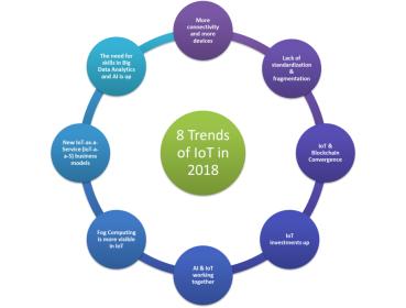
In 2018, IoT will see tremendous growth in all directions; the following 8 trends are the main developments we predict for next year:


Trend 1 —Lack of standardization will continue
Digitally connected devices are fast becoming an essential part of our everyday lives. Although the adoption of IoT will be large, it will most likely be slow. The primary reason for this is lack of standardization.

Though industry leaders are trying to develop specified standards and get rid of fragmentation, it will still exist. There will be no clear standards in the near future of IoT. Unless a well-respected organization like IEEE stepped-in and leads the way or the government imposes restrictions on doing business with companies if they are not using unified standards [6].

The hurdles facing IoT standardization can be divided into 3 categories; Platform, Connectivity, and Applications:

  • Platform: This part includes the form and design of the products (UI/UX), analytics tools used to deal with the massive data streaming from all products in a secure way, and scalability.
  • Connectivity: This phase includes all parts of the consumer’s day and night routine, from using wearables, smart cars, smart homes, and in the big scheme, smart cities. From the business perspective, we have connectivity using IIoT (Industrial Internet of Things) where M2M communications dominating the field.
  • Applications: In this category, there are three functions needed to have killer applications: control “things”, collect “data”, and analyze “data”. IoT needs killer applications to drive the business model using a unified platform.

All three categories are inter-related, you need all them to make all them work. Missing one will break that model and stall the standardization process. A lot of work needed in this process, and many companies are involved in each of one of the categories, bringing them to the table to agree on a unifying standards will be a daunting task [12].

Trend 2 — More connectivity and more devices
The speedy proliferation of IoT in past 3 years has resulted in billions of interconnected devices. As the consumer continues to stay hooked to more gadgets. The number of connected devices grew exponentially every year. By 2018 it will at least double and touch a whopping the mark of 46 Billion by 2021. More IoT devices will enter the channels, more than ever before. A clear indication of our direct dependency over the gadgets and that’s how our future is shaped.[6]

As IoT continues to expand we will certainly see an increase in devices connected to the network in different areas in business and consumer markets. Smart devices will become the de-facto for people to manage IoT devices. The benefits of using smart devices in that capacity include boosting customer engagement, increasing visibility, and streamlining communication that will include new human-machine interfaces such as voice user interface (VUI) or Chatbot.[4][2]

Trend 3 — “New Hope” for security: IoT & Blockchain Convergence
As with most technology, security will be the major challenge that needs to be addressed. As the world becomes increasingly high-tech, devices are easily targeted by cyber-criminals. Evans Data states that 92% of IoT developers say that security will continue to be an issue in the future. Consumers not only have to worry about smartphones, other devices such as baby monitors, cars with Wi-Fi, wearables and medical devices can be breached. Security undoubtedly is a major concern, and vulnerabilities need to be addressed.

Blockchain is a “new hope” for IoT Security. The astounding conquest of Cryptocurrency, which is built on Blockchain technology, has put the technology as the flag bearer of seamless transactions, thereby reducing costs and doing away with the need to trust a centered data source.

Blockchain works by enhancing trustful engagements in a secured, accelerated and transparent pattern of transactions. The real time data from an IoT channel can be utilized in such transactions while preserving the privacy of all parties involved.[4][2]


The big advantage of blockchain is that it’s public. Everyone participating can see the blocks and the transactions stored in them. This doesn’t mean everyone can see the actual contents of your transaction, however; that’s protected by your private key.

A blockchain is decentralized, so there is no single authority that can approve the transactions or set specific rules to have transactions accepted. That means there’s a huge amount of trust involved since all the participants in the network have to reach a consensus to accept transactions.

Most importantly, it’s secure. The database can only be extended and previous records cannot be changed (at least, there’s a very high cost if someone wants to alter previous records). [10][3][4] [7]

In 2018 increased interest in Blockchain technology will make the convergence of Blockchain and IoT devices and services the next logical step for manufacturers and vendors, and many will compete for labels like “Blockchain Certified”.

Trend 4 — IoT investments will continue
IDC predict that spending on IoT will reach nearly $1.4 trillion in 2021. This coincides with companies continuing to invest in IoT hardware, software, services, and connectivity. Almost every industry will be affected by IoT, which means many companies will benefit from its rapid growth. The largest spending category until 2021 will be hardware especially modules and sensors, but is expected to be overtaken by the faster growing services category. Software spending will be similarly dominated by applications software including mobile apps.

IoT’s undeniable impact has and will continue to lure more startup venture capitalists towards highly innovative projects. It is one of those few markets that have the interest of the emerging as well as traditional venture capital. While the growth next year is firmly attested and the true potential is yet to be unearthed, IoT ventures will be preferred over everybody else. Many businesses have assured adding IoT to their services model from the Transportation, Retail, Insurance and Mining industries [4][6].

Trend 5 — Fog Computing will be more visible
Fog computing allows computing, decision-making and action-taking to happen via IoT devices and only pushes relevant data to the cloud, Cisco coined the term “Fog computing “and gave a brilliant definition for Fog Computing: “The fog extends the cloud to be closer to the things that produce and act on IoT data. These devices, called fog nodes, can be deployed anywhere with a network connection: on a factory floor, on top of a power pole, alongside a railway track, in a vehicle, or on an oil rig. Any device with computing, storage,andnetwork connectivity can be a fog node. Examples include industrial controllers, switches, routers, embedded servers, and video surveillance cameras.”

The benefits of using Fog Computing are very attractive to IoT solution providers, some of these benefits: minimize latency, conserve network bandwidth and operate reliably with quick decisions. Collect and secure wide range of data, move data to the best place for processing with better analysis and insights of local data. Blockchain can be implemented at the level of fog nodes too. [11]

Trend 6 — AI & IoT will work closely
Amalgamation of IoT data analytics with AI for applications ranging from elevator maintenance to smart homes, will progress rapidly over the coming two years. Platform and service providers are increasingly delivering solutions with integrated analytics designed to feed data directly into AI algorithms. Another important advantage of using AI is supporting the optimization and adaptation of both IoT devices and related processes and infrastructure.

AI can help IoT Data Analysis in the following areas: data preparation, data discovery, visualization of streaming data, time series accuracy of data, predictive and advanced analytics, and real-time geospatial and location (logistical data). [10]

Trend 7 — New IoT-as-a-Service (IoT-a-a-S) business models
Transformational business models will develop in many IoT verticals over 2018-2019, supported by Big Data and AI tools. In these models, the value is in the convenience of the service for end customers (on-demand and not requiring heavy upfront expenditure), and the usage data that is collected, analyzed, and fed back into suppliers’ businesses and processes.

But the potential for IoT business model transformation extends beyond this, to encompass an increasing variety of more complex, as-a-service business models that disrupt existing industries, particularly for areas such as heavy industry, transport and logistics, and smart cities.

For these industries, IoT solutions can enable more of an ongoing, managed service relationship with both technology providers and end customers. One selling point is that costs can be more directly linked to ongoing measured usage or to specific trigger events captured by IoT sensors (e.g., “break-the-glass” solutions in which sensors pick up when a building or car is broken into). Another is that costs may be spread over time, shifting from upfront Capex to a more regular Opex outflow. Examples of such models include lighting-as-a-service (L-a-a-S), rail-as-a-service (R-a-a-S), and even elevators-as-a-service (E-a-a-S).[1]

Trend 8— The need for skills in IoT’s Big Data Analytics and AI will increase
Dynamic data sharing is at heart of IoT and Big Data Analytics will be instrumental in building responsive applications. Integrating IoT data channels with AI to retrieve on demand analytical insights has already gained momentum this year and will definitely grow exponentially in 2018. Subsequently, the need for Big Data and AI skills will rise, while most IoT service providers have highlighted the shortage for such extensively skilled candidates, internal learning programs in close proximity with R&D has set to be launched in many companies.[1][10][8]

This article was published on IEEE-IoT
Ahmed Banafa Named No. 1 Top VoiceTo Follow in Tech by LinkedIn in 2016
Read more articles at IoT Trends by Ahmed Banafa
References:

[LIST=1]

  • http://www.ioti.com/strategy/five-internet-things-trends-watch
  • https://mobidev.biz/blog/iot-trends-for-business-2018-and-beyond
  • https://www.bayshorenetworks.com/blog/breaking-down-idc-top-10-iot-predictions-for-2017
  • https://readwrite.com/2017/10/03/6-iot-trends-2018/
  • https://lightingarena.com/internet-things-anticipated-trends-2018/
  • https://medium.com/@Unfoldlabs/seven-trends-in-iot-that-will-define-2018-2a47e763731c
  • https://datafloq.com/read/iot-and-blockchain-challenges-and-risks/3797
  • https://www.bbvaopenmind.com/en/five-challenges-to-iot-analytics-success/
  • https://www.bbvaopenmind.com/en/why-iot-needs-ai/
  • https://www.technologyreview.com/s/603298/a-secure-model-of-iot-with-blockchain/
  • https://datafloq.com/read/fog-computing-vital-successful-internet-of-things/1166
  • https://iot.ieee.org/newsletter/july-2016/iot-standardization-and-implementation-challenges.html

    All figures: Ahmed Banafa

    Also read:CEVA Ups the Ante for Edge-Based AI


  • What does a Deep Learning Chip Look Like

    What does a Deep Learning Chip Look Like
    by Daniel Nenni on 02-16-2018 at 12:00 pm

    There’s been a lot of discussion of late about deep learning technology and its impact on many markets and products. A lot of the technology under discussion is basically hardware implementations of neural networks, a concept that’s been around for a while.

    What’s new is the compute power that advanced semiconductor technology brings to the problem. Applications that function in real time, on real products are now possible. But what exactly does a deep learning chip look like? What technology drives these designs?

    I caught up with Mike Gianfagna recently to discuss deep learning and pose some of these questions. Besides buying lunch, Mike told me some interesting things about deep learning chips based on what’s happening at eSilicon.

    First of all, chips targeted at deep learning applications are often not “chips” at all using the traditional definition of a monolithic piece of silicon in a package. Rather, they are combinations of monolithic chips and massive external memories all integrated in a sophisticated 2.5D package. The use of 2.5D makes the whole process a good bit more complex but allows the delivery of significant new capabilities.

    If you poke around inside one of these 2.5D deep learning packages, you typically find HBM2 memory stacks, along with the associated HBM PHY and controller. High-speed SerDes is also typically needed for off-chip communication. The actual deep learning chip itself typically has optimized multiply-accumulate functions – many of them. These designs have a need for specialized on-chip memories for efficiency and power reasons. So, a deep learning chip looks something like this:

    To really take advantage of advanced silicon technology, customization to optimize deep learning algorithms is a very good strategy. That means building ASICs, and that’s where eSilicon comes in. There aren’t many places you can go to implement a deep learning ASIC. There are lots of technical challenges involved.

    Performance demands use of FinFET technology, and that raises the stakes quite a bit. FinFET-class ASICs are substantially more challenging to design than older planar technology chips. Customizing memory for the multiply-accumulate design is tricky to get correct. Interfacing HBM memory stacks to the ASIC also requires very high-performance circuits – something not everyone is good at. And then there’s the 2.5D package. Integrating multiple components on a silicon interposer requires a lot of skill as well. Assembly yield is impacted by thermal and mechanical stress. Testing these devices also requires some new approaches, as does the actual design of the interposer itself.

    And on top of all this, Mike explained that it takes a team of ecosystem partners to get the job done. Critical IP is typically sourced from more than one vendor. Fabrication of the chip is done by the foundry, but HBM memory stacks, interposers and 2.5D packages all come from other vendors. It takes a well-coordinated team to get all this done reliably.

    As the lattes were being served at the end of our lunch, Mike told me about an event at the Computer History Museum in Mountain View on March 14. eSilicon is teaming up with Samsung Memory, Amkor and Northwest Logic to explain how that group of ecosystem partners works together to build deep learning ASICs. They also have a keynote address from Ty Garibay, the CTO of Arteris IP. I’ve been to eSilicon events in the past and they are typically very informative. The wine and food are pretty good, too. If you want to dig into deep learning I would attend this event, absolutely. Check out more about the seminar, or register to attend. SemiWiki will be there.

    Also read: High Performance Ecosystem for 14nm-FinFET ASICs with 2.5D Integrated HBM2 Memory


    Why It’s A Good Idea to Embed PVT Monitoring IP in SoCs

    Why It’s A Good Idea to Embed PVT Monitoring IP in SoCs
    by Daniel Payne on 02-16-2018 at 7:00 am

    At Intel back in the late 1970’s we wanted to know what process corner each DRAM chip and wafer was trending at so we included a handful of test transistors in the scribe lines between the active die. Having test transistors meant that we could do a quick electrical test at wafer probe time to measure the P and N channel transistor characteristics, providing valuable insight for the specific processing corner. We would’ve loved to have this kind of test transistor data for processing embedded into each die as well. The increase in transistor complexity for DRAM chips has been quite dramatic over the years, so in 1978 we had 16Kb DRAM capacity while today the technology has reached 16Gb, an increase of 1,000,000X. On the SoC side we see an equally impressive increase such that a GPU from NVIDIA now contains 21 billion transistors and 5,120 cores using a 12nm process from TSMC. So whether you are designing a CPU, GPU, SoC or a chip for IoT applications requires that IC designers understand how process variability impacts each die and packaged part during operation. Other design concerns include:

    • Manufacturability and yield
    • Timing, clock speed, power values within spec
    • Reliability effect like aging, internal voltage drop
    • Avoiding field failures

    Moore’s Law has held up pretty well until the 28nm node, and below that node the price learning curve hasn’t been as rewarding. Even clock speeds have stalled in the GHz range. Short-channel effects started to hurt current leakage values, limiting battery life and performance, so new transistor approaches emerged like FinFET and SOI. Device variability is a dominant design issue today, meaning that even adjacent transistors on the same die can have different Vt (Voltage Threshold) values caused by different dopant values or silicon stress caused by proximity to isolation wells – layout dependent effects. Just take a look at how variations have increased with each smaller geometry node from 90nm down to 22nm:


    Switching speed delay variations against supply voltage across process nodes (Source: Moortec)

    For a 22nm process node with a 475mV supply level you can expect switching speed delay variations of 25%, while at the more mature process node of 90nm the delay variations are only 9%.

    With FinFET technology in use since 22nm there are some new concerns caused by higher current densities like localized heating effects, so designers using 14nm, 10nm, 7nm and 5nm need to be aware of self-heating because it impacts the aging of transistors and the Vt actually begins to shift over time as shown below:


    Vth degradation from NBTI and HCI effects (Source: Moortec)

    The dark curve above shows a Vdd value of 1.3V being used for transistors, and over a 10 year operating period the nominal Vt value of 0.2V can be changed by over 4% due to negative bias temperature instability (NBTI) and hot carrier injection (HCI) effects. That Vt shift can simply slow down your IC or cause it to fail meeting your clock speed specification.

    With lower Vdd values being used coupled with higher current levels and higher interconnect resistivity you can expect to see internal supply levels of a chip drooping from the values supplied at the pins. Knowing the actual internal Vdd levels can be quite critical.

    To meet stringent power consumption requirements many approaches have been taken, a popular technique is called Dynamic Voltage and Frequency Scaling (DVFS) where the chip has the ability to change local Vdd values in order to throttle or speed up the frequency of operation. Reducing the Vdd value quickly reduces power consumption because power is related the square of the Vdd value. So lowering the Vdd value locally allows you to tune for power consumption. Adding DVFS does increase the logic overhead and requires even more simulation during the design phase. Turning local Vdd lines on causes a rush of current, triggering an IR drop issue which can cause transient errors in the silicon logic behavior.

    IC designers can deal with all of these effects by a couple of approaches, the earliest approach was to design for worst-case conditions although at the expense of leaving margin on the table. A newer approach is to actually embed in each chip some specialized IP for three tasks:

    • Temperature sensing
    • Voltage monitoring
    • Process monitoring

    Knowing your actual PVT (Process, Voltage, Temperature) corner in silicon is incredibly useful to controlling your chip for maximum performance. With an embedded PVT monitor you can quickly perform speed binning without having to run extensive functional, full-chip testing. Aging effects on Vt can be measured with an embedded PVT methodology.

    Using a temperature sensor at strategic locations on an SoC can then be used to dynamically measure how hot each region is, then decide to alter the Vdd values to keep the chip operating reliably while still meeting timing, even as the chip ages over time. A multi-core SoC with temperature sensors can dynamically assign new instructions to the core with the lowest temperature value, balancing the work load so as to not over-heat any one core with too many sustained operations. The mean time to failure for ICs is directly related to operating temperature levels, so with embedded PVT you can control the aging effects.

    Moortec is the IP vendor that designed PVT monitoring for popular process nodes and they have internally created the sensors and controllers to interpret the data on-chip. Yes, you have to use a tiny amount of silicon area to implement the PVT monitoring, however the benefits far outweigh the die size impact. The process monitor can tell you the exact speed of your transistors to let you know how close they are to nominal values. Benefits of using these monitors include:

    • Tuning on-chip parameters at product test
    • Real-time managements of processor cores
    • Avoiding localized aging effects
    • Maximizing clock performance at a specific voltage and temperature

    You can use PVT monitors to measure if your specific silicon will meet timing goals, or program local Vdd levels to achieve a certain clock speed. It also can make sense to have multiple PVT monitors spread out across a single die in order to collect regional data. For example you could place a PVT monitor in each corner of a die, then one in the center in order to measure process variability. For multi-core SoCs you would place PVT monitors in each core, next to critical blocks.

    Engineers at Moortec have designed PVT monitors across a wide range of process nodes starting at 40nm and extending through 7nm, so you don’t need to be a PVT expert to use their IP. You get to consult with their experts about which PVT monitors to use and where to place them on your specific chip design. To really get the most performance out of advanced FinFET nodes you should consider adding PVT monitors into your next design, even the battery-powered IoT designs benefit from the data gathered by PVT monitors in saving power consumption.

    There’s an 11 page white paper available at Moortec for download after a brief sign-up process.