webinar banner AI 2026 v2

The RISC-V Revolution is Sweeping Across the APAC Region and Australia

The RISC-V Revolution is Sweeping Across the APAC Region and Australia
by Daniel Nenni on 06-10-2019 at 9:14 pm

Join SiFive Tech Symposiums in Tokyo, Daejeon, Pangyo, Hsinchu, Singapore and Sydney

As we make our way around the world meeting and engaging with others in the semiconductor and hardware design community, we are seeing an increased interest in RISC-V based hardware innovation. This is due in large part to the emergence of  market-ready RISC-V core IP, development tools and silicon solutions based on cloud-based design platforms that facilitate the creation of custom SoC solutions for edge computing, AI, IoT, wearable, server and other target vertical markets.

Having just completed an exciting tour through Europe, we’re gearing up for our visit to the APAC region and Australia, which will take place throughout the month of June. If you live in the region, or will be visiting, you won’t want to miss this. Here is a glimpse of what’s in store for attendees. For more details, and to register to attend any of our great symposiums, please visit www.sifivetechsymposium.com


Tokyo Highlights

Software Hardware Consulting Group, a company specializing  in FPGA and SoC microcontroller IP solutions, embedded security, voice, speech, wired and wireless connectivity, will be our co-host. This symposium will take place on Tuesday, June 11 and includes keynotes by Huzefa Cutlerywala, VP of sales (APAC) for SiFive, and Shumpei Kawasaki, CEO of Software Hardware Consulting Group. There will also be presentations by our customer, QuickLogic, and ecosystem partners, including DTS Insight, IAR Systems and Rambus. Attendees will also have an opportunity to see demonstrations and learn about the latest design platforms for RISC-V based SoCs, development boards, IP, software and more. For more information, and to register for the symposium in Tokyo, please visit: https://sifivetechsymposium.com/agenda-tokyo/


Daejeon Highlights

The Korea Advanced Institute of Science and Technology (KAIST) will be our co-host. This symposium will take place on Monday, June 17 and will include presentations from Yunsup Lee, alumni of KAIST and co-founder and CTO of SiFive, and Keith Witek, SVP corporate development and strategy at SiFive. There will be presentations by our partners, IAR Systems, UltraSoC and OpenEdges Technology, as well as other companies, including Samsung and FuriosaAI. Attendees will also have an opportunity to see demonstrations and learn about the latest design platforms for RISC-V based SoCs, development boards, IP, software and more. For more information, and to register for the symposium in Daejeon, please visit: https://sifivetechsymposium.com/agenda-daejeon/


Pangyo Highlights

The Korea Semiconductor Industry Association (KSIA) will be our co-host. This symposium will take place on Tuesday, June 18, and will include presentations from Yunsup Lee co-founder and CTO of SiFive, and Keith Witek, SVP corporate development and strategy at SiFive. There will also be presentations by many ecosystem partners, including UltraSoC, Rambus, OpenEdges Technology, Hancom MDS and IAR Systems, as well as other companies, including Samsung and FuriosaAI. Attendees will also have an opportunity to see demonstrations and learn about the latest design platforms for RISC-V based SoCs, development boards, IP, software and more. For more information, and to register to attend the symposium in Pangyo, please visit: https://sifivetechsymposium.com/agenda-pangyo/


Hsinchu Highlights

Microchip and ACTT are our co-hosts in Hsinchu. This event will take place on Tuesday, June 18, and features a great lineup of speakers. There will be keynotes by Thomas Xu, the CEO of SiFive China, Jianjun Xiang, CEO of ACTT, Vishakh Rayapeta, applications engineer at Microchip, Christopher Moezzi, VP and GM AI/ML Solutions BU of SiFive, and Jimmy Hu, VP of R&D at SiFive China. There will also be presentations by Imagination Technologies, Industrial Technology Research Institute and Rambus. Attendees will also have an opportunity to see demonstrations and learn about the latest design platforms for RISC-V based SoCs, development boards, IP, software and more. For more information, and to register to attend the symposium in Hsinchu, please visit: https://sifivetechsymposium.com/agenda-hsinchu/


Singapore Highlights

This symposium will take place on Wednesday, June 19, and will be hosted at the prestigious National University of Singapore. Some of the highlights include keynote presentation by Huzefa Cutlerywala, VP of sales APAC at SiFive, and presentations by Anand Bariya, VP of engineering at SiFive, and Trevor Carlson, assistant professor at the National University of Singapore. There will also be myriad presentations by industry veterans and luminaries. Attendees will also have an opportunity to see demonstrations and learn about the latest design platforms for RISC-V based SoCs, development boards, IP, software and more. For more information, and to register to attend the symposium in Singapore, please visit: https://sifivetechsymposium.com/agenda-singapore/


Sydney Highlights

Morse Micro will be our co-host in Sydney. This symposium will take place on Friday, June 21. Some of the highlights include keynote presentations by Huzefa Cutlerywala, VP of sales APAC at SiFive, and Michael De Nil, co-founder of Morse Micro. There will also be a presentation by Anand Bariya, VP of engineering at SiFive and a member of the faculty at the research lab at the University of Sydney, as well as myriad presentations by industry veterans and luminaries. Attendees will also have an opportunity to see demonstrations and learn about the latest design platforms for RISC-V based SoCs, development boards, IP, software and more. For more information, and to register for the symposium in Sidney, please visit: https://sifivetechsymposium.com/agenda-sydney/



Cadence on 5G Intelligent System Design #56thDAC

Cadence on 5G Intelligent System Design #56thDAC
by Daniel Nenni on 06-10-2019 at 10:00 am

As much as I love all EDA vendors I must say Cadence did the best DAC this year. Great booth, great location, excellent content, and of course a great party. The 5G presentation in the Cadence booth by Ian Dennison was of great interest to me as I am still trying to wrap my head around this whole 5G thing. I was able to meet with Ian privately and he sent me his slides. It is a very detailed presentation covering a lot of data so it is a multi-blog sort of deal.

5G is a bit controversial in my neighborhood. There is a NIMBY (not in my back yard) movement that opposes towers which are based on the current 4G implementation that are admittedly a bit unsightly. As a result we have a big dead spot in my area where I cannot get 4G and I can only imagine what 5G will bring our quiet little hamlet.

I had not met Ian before so it was a pleasure. Ian is a 33 year semiconductor veteran that came to Cadence through an acquisition in 1994 and he has resided there ever since. He works in the Cadence Intelligent System Division in Edinburgh researching systems design, analog design, future flows, and emerging markets. Ian’s presentation “Cadence 5G Intelligent System Design” fits right into that description, absolutely.

If you look at the transformation of EDA over the last 35 years you will see a clear path to systems design which is where we are today. Mobile, Industrial IoT, Datacenter, Automotive, Aero/Defense, and Health Care are all critical systems that revolve around semiconductor technology. Bottom up design includes Analog, RF, Digital, device support, Embedded Software and Security, and Systems Analysis. Machine Learning is now an important part of the systems design equation with the massive amounts of data at our disposal.

5G is an easy example of the complexities we face as an industry. No matter how much coverage and bandwidth we provide it will be quickly used and abused. The critical part of modern semiconductor design is creating chips and systems that can thrive inside the infrastructure of the United States. China is another story of course since they don’t have NIMBYs.

The slide above is a breakout of a 5G Subsystem. The existing 4G towers with a mast radiohead and baseband (placed every 2-3km) will continue to provide 4G and slower 5G services. Much less invasive 5G mmWave radioheads can then be embedded in populated areas (every 200m). Yes, you can put one on the streetlight in front of my house, no problem.

The invasive infrastructure here of course is the edge computing subsystem which is about the size of a shipping container so NIMBYs beware. With the coming onslaught of AI for literally everything we do it will not be possible for our edge devices (smartphones, autonomous cars, delivery drones, etc…) to manage ALL of the computation AI will require. Nor will our 4g/5G/6G networks ever be able to handle ALL of the data generated from an autonomous edge.

In my neighborhood we have taken to making exposed infrastructure into art. Hopefully we can do the same for the Edge Computing Subsystems because, again, we will never have enough compute power and if we are to be competitive as a country we will have to both innovate and accommodate.

For further investigation Cadence has a 5G Landing Page. It talks about 5G Systems and Subsystems, 5G Handset, 5G Radioheads, 5G Baseband and Edge Computing, plus 5g Front Haul and Back Haul. Also listed are Cadence related products for each of the landing pages, definitely worth a look.


The Integrated Circuit

The Integrated Circuit
by John East on 06-10-2019 at 5:00 am

The “20 Questions with John East” series continues

Noyce and the rest of the traitorous eight left Shockley without a clue as to what they would do next.  They believed in semiconductors and knew that they were the very best semiconductor guys in the world.  Their hope was to find a company who would hire them en masse.  After some false starts, Noyce was introduced to Sherman Fairchild. Fairchild was a scientist / engineer who had turned entrepreneur.  Among the many companies he had started was Fairchild Camera.  The company was very successful:  during World War II more than 90% of the military reconnaissance cameras bought by the American forces were made by Fairchild Camera.  Sherman Fairchild saw the potential of semiconductors.  He and Noyce put together a deal.  In 1957 Fairchild opened a new business segment:  Fairchild Semiconductor.  It was located in Palo Alto, populated initially only by the traitorous eight, and its president was Bob Noyce.  Bob worked for a man named John Carter, Fairchild’s CEO, who was based in the corporate headquarters in Long Island, New York.  Then— the event that changed the world.  In 1959, Noyce invented the integrated circuit.  At just about the same time, Jack Kilby, a Texas Instruments engineer also invented the integrated circuit.  This led to some interesting times.

I knew both Bob and Jack.  They were probably the two nicest men I have ever met.  Over the years, they were quite complementary about each other.  Jack Kilby was as kind and gentle a man as you will ever meet.  That was a good thing because he was huge.  I’d guess six feet eight or six nine with a big frame.  When I shook his hand, I felt as though he could crush mine if he chose to.  Luckily he didn’t.  Bob Noyce was the greatest “people” guy that you ever met.  After one meeting with him, you walked away feeling like you were his best friend.  He was a really likeable guy with tons of charisma.

Kilby’s patent specified putting all the components on the same piece of germanium, but he interconnected them with wire bonding techniques.  Obviously this was totally unpractical with respect to making a real IC.  But Bob Noyce got it right.  His patent put all the components on the same silicon chip and interconnected them with deposited, patterned, and etched metal  — just the way we still make them today.  The Noyce patent is displayed on a plaque in front of the Charleston Road building where he made the invention.  Kilby beat Noyce to the punch (and to the patent office) by six months, but you couldn’t make an IC without Noyce’s metalization.  After a big legal battle, TI and Fairchild cross licensed their patents and that was the end of it except for the ongoing arguments over which state should get the credit — Texas or California.  Since I was born in Texas and live in California, I feel confident that, if this thing is ever really settled, I’ll come out on the winning side.

While I’m at it, a little bit about Moore’s law. Everybody knows about Moore’s Law.  But here’s some perspective from 1965.  When Gordon Moore first articulated his “law”, he was predicting that the number of components on a chip would double from a starting point of 32 components in 1964 to a gargantuan 64 components in 1965.  The logarithmic graph that he published was so bold as to predict a time when there would be 64 thousand components on a chip.  To the guys in the fab trying to make these things, that seemed crazy!!  I know it seemed crazy to me when I got there in 1968!  Gordon firmly believed in the 64K number, but if you had asked him about 64 million, he probably would have thought you were nuts.  Today we’re doing on the order of 64 billion.  Wow.  Sounds like more Alice in Wonderland stuff, doesn’t it?

Fairchild moved to a bigger facility in Mountain View in 1960. They had started on Charleston Rd in Palo Alto.  That building is still there.  It’s a Historical Landmark. The new facility comprised a headquarters building at 313 Fairchild Drive and an adjacent manufacturing building at 545 Whisman Road in Mt View.  Later they added the “Rust Bucket” (The metal framed structure was painted in an orange color that looked like rust) on Ellis Street.  When I reported to work on September 9, 1968, I headed to 545 Whisman Road where I spent the next eight years.

Eventually, working for John Carter drove Noyce nuts.  Carter didn’t see the potential of semiconductors.  He didn’t want to spend the money to do the job right.  He had an east coast management style which was very, very different from the style that had developed in the Bay Area semiconductor business.  He didn’t believe in stock options for the rank and file.  This friction and other issues eventually led to Carter’s resignation, but Sherman Fairchild decided not to give the top job to Noyce, who thought he deserved it.

Noyce and Moore decided to leave.  Andy Grove, who was running part of the Palo Alto R&D labs, heard about it and asked to join them.   (More about Andy later) They left in June 1968.  I had accepted my job in May.  They left in June.  Hence, all the craziness in my “Day One” and “Off with their heads” chapters.  In order to fill Noyce’s position, Sherman Fairchild recruited Lester Hogan.  Les had been running the semiconductor division of Motorola. Earlier in his career, Hogan had worked under Bill Shockley at Bell Labs.  Hogan agreed to join, but only if he could bring eight of his best people along with him.  Fairchild agreed.  In they came.

And the stuff hit the fan!!

See the entire John East series HERE.

Pictured: The contenders for the title of “Inventor of the integrated circuit”.  On the left Jack Kilby.  On the right Bob Noyce.  In my view  the title goes to Bob, but Jack was a really smart guy and the nicest man I ever met

Getting Real about Vehicle Data

Getting Real about Vehicle Data
by Roger C. Lanctot on 06-09-2019 at 9:56 pm

There is a lot of talk about data being the new oil fueling the automotive industry. Industry interest began in earnest in 2016 when McKinsey published a report – “Monetizing Car Data” – that noted in the executive summary that the car data market could be as large as $450B-$750B by 2030.

McKinsey: Monetizing Car Data – https://tinyurl.com/y85pk8nu

There’s nothing like big numbers to get the attention of a large, slow-moving industry. Since the publication of that report, car companies and their suppliers have been in a rush to figure out how to capture this value, while regulators have moved to put privacy barriers in place and warn of cybersecurity risks.

Strategy Analytics is hosting a discussion on the topic of data monetization myths this week in Tel Aviv, Israel, with executives representing industry leaders including: OtonomoGeneral MotorsHarman International, and Continental Corporation.  These executives will address the range of issues related to vehicle data including my particular bugbear: the fact that vehicle data is not only more interesting and valuable to car makers than it is to consumers, but also that car makers should feel an obligation to collect vehicle data thereby taking responsibility for vehicle performance.

Seminal though McKinsey’s report may have been, it failed to take into account the emerging cross-OEM data sharing and aggregation that will be necessary to tap into the deepest veins of vehicle data value. It is also blind to the massive value aggregation occurring daily at Tesla Motors as the company hoovers up data related to autonomous driving edge cases.

The rich world of new mobility services and smart cities seen to be on the horizon will not arrive without vehicle connections and data collection.  Precisely how that is coming to pass today will be discussed this Wednesday, June 12th, at the Crowne Plaza City Center in Tel Aviv.  There are a few seats left for the event. If you are in Tel Aviv and are interested in attending, please contact my colleague, Serge Rozenblum, at srozenblum@strategyanalytics.com.

Event details:

Fireside Chat: Managing and Monetizing Vehicle Data – Dispelling the Myths on Wed, June 12th 1:30-3:00.

 At Crowne Plaza City Center (Azrieli) (Tel Aviv) – Hall A – floor 11

 Strategy Analytics’ Director of Mobility, Roger Lanctot, moderating a discussion with:

Ben Volkow, Otonomo, Founder and CEO

Dr. Barak Hershkovitz, General Motors, Director Future Mobility Engineering, Director Global EV Customer Experience

Hadas Topor Cohen, Harman, Senior Director, Head of Products Software Platforms Product Unit

Dr Karoline Bader, Continental, Senior Manager Business Development & Strategy

We have limited seating for this event, so kindly RSVP soon by sending an email.

We look forward to welcoming you.


Samsung Foundry Update 2019

Samsung Foundry Update 2019
by Tom Dillinger on 06-08-2019 at 5:00 am

Samsung Foundry recently held their 4th annual technology forum in Santa Clara.  This article reviews the highlights of the presentations.  There were two prevalent themes throughout – focused execution on the current process roadmap, and the introduction of the 3nm process node features and schedule.

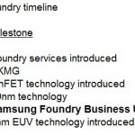
Before getting into the technical details, here is a brief review of the “new” Samsung Foundry.  A timeline of the foundry services is appended below.

The 2017 milestone above is significant – the Samsung Foundry organization was created as a distinct business unit.  Yongjoo Jeon, from the Samsung Foundry marketing team, explained, “Samsung Foundry operates independently from the company’s product divisions.  We leverage the research progress of the R&D arm of Samsung Semiconductor – nevertheless, all customers are equal.”

Dr. E.S. Jung, President of Samsung Foundry, added, “We are focused on delivering exceptional foundry services – from our semiconductor and packaging technology roadmap, to our operational execution, to our strengthened IP capability and design services support.  We are announcing design enablement on the cloud, as a result of our partnership with AWS and Azure, in collaboration with Cadence and Synopsys.  We are proud of our 100% on-time delivery the past two years.  There is a commitment to invest $100B in fabrication capabilities over the next 10 years. We are dedicated to becoming the most trusted foundry.”

Execution

Here is a brief summary of the semiconductor process roadmap status.  The axes on the figure below are the major process node updates (“Innovation”) and the incremental node enhancements (“Evolution”).

The typical nomenclature for a process node uses both an “Early” (E) and a “Performance” (P) designation.


14/11

  • 2M+ wafer shipped, cumulative since 1Q’2015
  • ”Initial customers were in mobile markets, now additional HPC and automotive applications are using these nodes.”

10/8

  • 800K+ wafer shipped, cumulative since 4Q’2016
  • HPC and mobile market applications initially, now additional consumer products
  • “This will be a long-life node for very cost-sensitive products, until the cost cross-over occurs for 7nm.”
  • 8LPP: 44nm Mx pitch
  • 8LPU: ULVT, 1 fin standard cell template with both single- and double-diffusion break (8LPU introduced an ULVT device for HPC applications, compared to 8LPP)

7/6/5/4

  • 7nm entered high volume manufacture (HVM) in 4/19
  • 7/6 utilize “high single digit” EUV mask layers, with a slight increase for 5nm
  • 7nm offers both unidirectional Mx (36p) and bidirectional line/space patterning (40p)
  • When asked about EUV “maturity”, Samsung Foundry indicated, “All EUV fabs collaborate closely with ASML – in that regard, the equipment capabilities are the same. Yet, we have extensive experience with EUV litho on both cuts and lines – extending that knowledge to more layers for nodes after 7nm has process smoothly.  And, Samsung has internally developed EUV mask inspection technology, a unique capability within the industry.”  Improved detection of EUV (reflective, multi-layer) mask defects is a distinct cost benefit.
  • 6nm starts HVM in 2H’2019
  • 6nm offers scalability benefits with block re-implementation, while retaining existing (hard) IP reuse – “smart scaling” is the term used by Samsung Foundry. Re-implementation can realize a 10% area gain, with comparable power reduction.
  • 5nm has entered risk production (6T , single fin std cell library), with HVM in 1H’2020
  • 4nm process development will complete in 2H’2019
  • 4nm adds to the EUV layer process integration – e.g., 4LPE offers 28nm M1 pitch with a double-EUV exposure

The following chart summarizes the key features of these leading process technologies.

Company Samsung
Process 7LPP 6LPP 5LPE 4LPE
Metal Pitch(nm) 36(M3) 36(M3) 36(M3) 32(M3)
Tracks 6.75 6.75 6 6.25
Cell Height(nm) 243 243 216 200
CPP(nm) 54 54 54 54
DDB/SDB DDB SDB SDB SDB
Transistor density(MTx/mm2) 101.6 119.9 134.9 145.7
Density versus 7nm 1.33 1.43
Layers EUV/Total -3 0 +8

Specialty Technologies

  • 28FDS (FD-SOI) has been widely adopted, with a significant number of new tapeouts planned for 2019
  • 28FDS added an embedded Magnetoresistive RAM (eMRAM) process module, introduced in 3/2019
  • The plans for eMRAM will extend to the 18FDS node (with automotive grade qualification in 2020), and in the future, to FinFET nodes.
  • 18FDS: PDK 0.5 was shipped in 9/2018, v1.0 available in 6/2019, Design Kit v1.0 in 12/2019

Here is a brief comparison between 28FDS and 18FDS.

RF

The timeline for RF design enablement for mmWave applications (e.g., 5G) is depicted below.

In addition, Samsung Foundry indicated they are focusing on providing analog and RF design services, at a range of potential interfaces with customers – Level0: spec handoff;  Level1: architecture handoff; Level2: IP porting.

Packaging

In addition to the semiconductor process node and 3GAE introduction, Samsung Foundry presented the breadth of their advanced 2.5D and fan-out packaging technologies.  The FO packaging offering is based on Samsung’s unique “panel-level” form factor (FO-PLP).  The 2.5D multi-die offering provides integration of logic and HBM modules with an interposer.

3GAE

The big announcement was the availability of PDK v0.1 for the 3nm process node (3GAE), by Dr. H.K. Kang, EVP, Samsung Semiconductor R&D Center.  This node transitions from vertical FinFET devices to a gate-all-around implementation, a structure that Samsung Foundry denotes as a “Multi-Bridge Channel FET” (MBCFET).  The figure below from Samsung Foundry provides a high-level depiction of the GAA device.


Note that there are multiple, horizontally-oriented “nanosheets” stacked vertically, with a surrounding gate electrode – the effective device width would be (2*(thickness + width) * # of sheets).  (The Samsung Foundry presentations were a little vague on the specific 3GAE implementation – there were different slide images depicting 2, 3, and 4 vertical nanosheets.)  Of specific note is that the GAA device width is now a design parameter, enabling a wider range of design optimizations.

The figure below illustrates how a FinFET layout (3 fins) compares to a GAA implementation – unlike the quantized height of the active area associated with the fins, the width of the nanosheets is a design variable.


The PPA comparisons from 7nm to 3GAE were impressive (using Ion-versus-Ioff type data):  +35% performance, -50% power (@ iso perf., -40% power at fmax), -45% area.

With the improved channel electrostatics of the gate-all-around topology, the subthreshold slope data presented was impressive.  The supply voltage VDD for 3GAE will scale to 0.7V.

The 3GAE presentation described three device Vt offerings:  RVT (~0.35V);  LVT (~0.25V), and SLVT (~0.15V) – refer to the figure below.  The Pelgrom chart of deltaVt versus (gate_area **0.5) showed comparable Vt mismatch variation to FinFET offerings.  Dr. Kang indicated, “Samsung Semiconductor R&D has been working on GAA technology for some time.  The most difficult process integration step was to develop the replacement gate technology to provide multiple Vt offerings.”

See patent #US7002207, culminating in the IEDM 2018 technical paper:  Bae G., et al., “3nm GAA Technology featuring Multi-Bridge-Channel FET for Low Power and High Performance Applications”, International Electron Devices Meeting (IEDM), 2018, p. 28.7.1 – 28.7.4.  The figure below is from that paper, highlighting the use of different work function metals to provide the Vt options.


Similarly, the local deltaT temperature increase due to device self-heating was comparable to FinFET topologies.  Bias temperature instability (BTI) drive over time was similar, as well.

Design enablement for the 3GAE process was announced, as part of the v0.1 PDK release to customers.  Specifically, SPICE models will continue to utilize the BSIM-CMG compact model format, which includes a gate-all-around topology.  (Kudos to the Berkeley Device Model group for anticipating that the GAA electrostatic model would be needed.)  Place-and-route techfiles, pCells, and fill algorithms for layout implementation were released.  Parasitic extraction, DRC, and LVS runsets were also part of the v0.1PDK release.

As an aside, the parasitic capacitances for the GAA device will certainly differ from FinFETs.  The Cgs and Cgd sidewall parasitics for the gate traversing between fins are now reflected in the gate between the stacked nanosheets.   The spacing between nanosheets is a critical process optimization parameter – refer to the IEDM paper cited above.  The Cgx capacitance for the gate-over-substrate between fins is replaced by the capacitance to substrate of the gate below the bottom nanosheet.  The extracted gate resistance element, Rg, will also differ for the unique GAA cross-section.  (I’m planning on investigating the BSIM-CMG model for a GAA topology in more detail.)

Both 3GAE and 3GAP node introductions were presented on the process roadmap in the figure above.  As mentioned above, the v0.1 PDK release for 3GAE is available now.  The 3GAE node will enter risk production in late 2020, with HVM in late 2021.  (In my notes, I have written that the 3GAP dates will be roughly one year later.)

SAFE

Samsung Foundry also briefly described their “SAFE” program (Samsung Advanced Foundry Ecosystem), listing 16 EDA partners, 27 IP providers, and 27 design services solutions partners to assist customers.  As mentioned above, the ecosystem for (hybrid) cloud-based design was also introduced, utilizing the resources and expertise of AWS and Azure, and a collaboration with Cadence and Synopsys.

The first “SAFE” event highlighting the breadth of this partnership will be held in Silicon Valley on 10/22/2019.

When describing the recent collaboration with the EDA vendors, there was one example presented that caught my attention.  There’s been a lot of discussion on “how would machine learning principles apply to EDA algorithms” – an example was presented that I thought was extremely innovative.  The mask house currently employs a sophisticated set of Source-Mask Optimization (SMO) algorithms to realize a printable mask.  There is a risk that a layout topology may be unresolvable during SMO analysis.  Although the goal is to exclude any problematic layout topologies as part of the DRC design rule checking runset, the foundries have introduced the additional requirement for designers to execute a Lithography Process Checking (LPC) flow.  Initial LPC product releases integrated both model-based and pattern matching-based algorithms, to explore the layout for potential issues.  The model-based analysis is comprehensive but very computationally expensive.  The pattern matching approach is fast, but is “reactive”, in that it relies upon a set of patterns that have previously been identified.  Samsung Foundry and Mentor Graphics have integrated a set of algorithms into Calibre LPC that apply machine learning techniques to extend the scope of “litho hot spot” layout analysis beyond the provided pattern library, without the computational complexity of detailed model-based analysis – very cool.

Reference:  Kim, et al., “Machine learning to improve accuracy of fast lithographic hotspot detection”, SPIE, paper 10962-41, February 24-28, 2019.

Summary

Although in some regards Samsung Foundry is still “very young”, it was clear throughout the forum presentations that they are focused on execution of the existing process roadmap and are attempting to make a significant leap into the next generation device topology beyond vertical FinFETs.  The use of GAA technology will relax some of the design restrictions associated with the “quantized” FinFET device width, and the 3GAE process node PPA comparisons to existing nodes were extremely compelling.  Moore’s Law marches on.

For an overview of the 3GAE process node announcement, please refer to the following Samsung Foundry web link.

https://news.samsung.com/global/infographic-reduced-size-increased-performance-samsungs-gaa-transistor-mbcfettm

-chipguy


56th DAC Las Vegas Trip Report

56th DAC Las Vegas Trip Report
by Daniel Nenni on 06-07-2019 at 5:00 am

Having just returned from my 35th DAC I would like to share a few thoughts with the organizers, exhibitors, and attendees. In my experience it was a really well planned DAC. Personally, I like the Las Vegas venue even though it is not near a semiconductor populated city. Those who chose to attend this year were there for a reason which goes to the whole quality versus quantity argument. Unfortunately, a conference that does not grow or at least maintain attendance will die so San Francisco here we come.


Noticeably missing was ARM. What were you people thinking? DAC is now a RISC-V Conference!

For me the most interesting topic was the cloud. I know we have been talking about it for many years but now we are seeing case studies and tape-outs. The most interesting discussion came after one of my book talks in the Methodics booth. A friend of mine now works for Google designing chips. Can you imagine what it is like designing chips for a company that does not sell the chips (cost and delivery are not the driving factor) and has a massive cloud at their disposal? To put it bluntly my friend was like a kid in a candy store. He can now design a much better quality chip without having to worry about lengthy simulation and verification runs. To be clear, you can bet Google chip designers get silicon right the first time, absolutely.

I mentioned this in my DAC presentation Semiconductors: Past, Present, and Future. When I arrived in the semiconductor industry in 1984 systems companies made their own semiconductors. I worked for Data General and we made our own CPUs until Motorola (an IDM) and SUN Microsystems put us out of business. Then Intel (IDM) took over and dominated the semiconductor CPU business. The next disruption where we went fabless was documented in our book Fabless: The Transformation of the Semiconductor Industry. Then the SoC revolution started with ARM and Qualcomm followed by Apple, Samsung, Huawei, and other mobile device companies. This is documented in our book Mobile Unleashed: The Origin and Evolution of ARM Processors in our Devices.

Today it is not only the mobile companies making their own SoCs, other systems companies such as Google, Facebook, Microsoft, and Amazon are making their own domain specific chips. You can also include automotive companies in the domain specific chip design mix. We can see this transformation first hand on SemiWiki with the domains that reach out to us on a regular basis. Tesla was on SemiWiki years ago in fact.

For new chip design companies the cloud is an easy decision. For the older fabless companies that have years and years of non-cloud culture and non-cloud infrastructure it is a very difficult change. The question I have is how are they going to compete with the natural born cloud chip designers?

Another example is eSilicon. After almost 20 years of designing ASICs in the traditional way, eSilicon has moved all of chip design into the cloud (eSilicon and Google presented Doing EDA in the Cloud ? Yes, it’s possible! at the DAC Design-on-Cloud Pavilion). eSilicon is also using machine learning to expertly optimize resources based on data from their numerous chip tape-outs.

The ASIC business is fiercely competitive where cost and time to market is critical to success. The question I have for other ASIC companies is how are they going to compete with eSilicon in the cloud?

For those of you who attended and supported DAC this year I thank you.  I met many new and old friends which is an important part of life. This picture was taken by Suk Lee of TSMC who is a VERY talented photographer. He expertly captured my wife’s newly highlighted hair.


Visual SLAM at the Edge

Visual SLAM at the Edge
by Bernard Murphy on 06-06-2019 at 5:00 am

SLAM – simultaneous localization and mapping – is critical for mobile robotics and VR/AR headsets among other applications, all of which typically operate indoors where GPS or inertial measurement units are either ineffective or insufficiently accurate. SLAM is a chicken and egg problem in which the system needs to map its environment to determine its place and pose in that environment, the pose in turn affects the mapping, and so on. Today there are multiple ways to do the sensing for SLAM, among which you’ll often hear LIDAR as a prime sensing input.


But LIDAR is expensive, even for newly emerging solid-state implementations and it’s still not practical for VR/AR. Also often overlooked for industrial robots, say for warehouse automation applications, is that the proofs of concept look great but current costs are way out of line. I recently heard that Walmart ordered a couple of these robots at $250k each – nice for exploring the idea, maybe even building warehouse maps, but not to scale up. Practical systems obviously have to be much cheaper in purchase, maintenance and down-time costs.

Part of reducing that cost requires switching to low-cost, low-power sensing and fast, low-power SLAM computation. Sensing might be a simple monocular or RGBD camera, so this becomes visually-based SLAM, which appears to be the the most popular approach today. For the SLAM algorithm itself, the best-known reference is ORBSLAM, designed unsurprisingly for CPU platforms. The software is computationally very expensive – just imagine all the math and iteration you have to do in detecting features in evolving scenes while refining the 3D map. That leads to pretty high power consumption and low effective frame-rates. In other words, not very long useful life between charges and not very responsive mapping, unless the robot (or headset) doesn’t move very quickly.

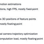
There are three main components to SLAM: tracking, mapping and loop closure. Tracking estimates the camera location and orientation. This has to be real-time responsive to support high frame rates (30FPS or 60FPS for example). This component depends heavily on fixed point operations for image processing and feature detection, description and matching (comparing features in a new frame versus a reference frame). Features could be table edges, pillars, doors or similar objects or even unique markers painted on the floor or ceiling for just this purpose.

Mapping then estimates the 3D positions of those feature points; this may add points to the map if the robot (or you) moved or the scene changed, and will also refine existing points. Computation here has to be not too far off real-time, though not necessarily every frame, and is mostly a lot of transformations (linear algebra) using floating-point data types.

In the third step, loop closure, you return to a point you have been before, and the mapping that you built up should in principle show you at that same point. It probably won’t, exactly, so there is opportunity for error correction. This is a lot more computationally expensive than it may sound. Earlier steps are probabilistic so there can be ambiguities and mis-detections. Loop closure is an opportunity to reduce errors and refine the map. This stage also depends heavily on floating-point computations.

So you want fast image processing and fixed-point math delivering 30 or 60FPS, a lot of floating-point linear algebra, and yet more intensive floating-point math. All at the low power you need for VR/AR or low-cost warehouse robots. You can’t do that in a CPU or even a cluster of CPUs. Maybe a GPU but that wouldn’t be very power-friendly. The natural architecture fit to this problem is a DSP. Vector DSPs are ideally suited to this sort of image processing, but a general-purpose solution can be challenging to use.

Why? Because a lot of what you are doing works with small patches around features in the captured (2D) images. These patches are very unlikely to nicely localize themselves into consecutive locations in memory, making them vector-unfriendly. For similar reasons, operations on these features (eg a rotation) become sparse matrix operations, also vector-unfriendly. This means that conventional cache-based approaches to optimization won’t help. You need an application-specific approach using local memory to ensure near-zero latency in accesses, which requires carefully-crafted DMA pre-fetching based on an understanding of the application need.

This works but then you have to be careful about fragmenting the image thanks to the inevitably limited size of that local memory which can, among other things, lead to a need to process overlaps between tiles, actually increasing DDR traffic. Finally, coordination with the CPU adds challenges, in sharing memory with the CPU virtual memory, in managing data transfers and in control, sync and monitoring between the CPU and DSP.

CEVA has added a SLAM SDK to their Application Developer Kit (ADK) for imaging and computer vision, designed to run with their CEVA-XM and NeuPro processors. The SLAM SDK enables an interface from the CPU allowing you to offload heavy-duty SLAM building-blocks to the DSP. Supplied blocks include feature detection, feature descriptors and feature matching, linear algebra (matrix manipulation and equation solving), fast sparse equation solving for bundle adjustment and more.

The ADK also includes a standard library of OpenCV-based functions, CEVA-VX which manages system resource requirements, including those tricky data transfers and DMA optimizations to optimize memory bandwidth and power, and an RTOS and scheduler for the DSP which abstracts and simplifies the CPU-DSP interface.

All good stuff, but what does this deliver? Talking to Danny Gal (Dir of computer vision at CEVA), I learned that the CEVA-SLAM SDK, running a full SLAM tracking module with a frame size of 1280×720 on the CEVA-XM6 DSP at 60 frames per second consumes only 86mW in a TSMC 16nm process. So yeah, it seems like this approach to SLAM is a big step in the right direction. You can learn more about this HERE.


#56DAC – Machine Learning and its impact on the Digital Design Engineer

#56DAC – Machine Learning and its impact on the Digital Design Engineer
by Daniel Payne on 06-05-2019 at 12:05 am

Tuesday Panelists

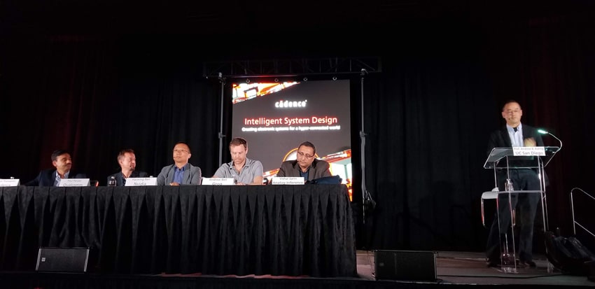
Tuesday for lunch at #56DAC I caught up to the AI/ML experts at the panel discussion hosted by Cadence. Our moderator was the affable and knowledgable Prof.  Andrew Kahng from UC San Diego. Attendance was good, and interest was quite high as measured by the number of audience questions. I learned that EDA tools that use heuristics and predictions are great candidates for AI/ML upgrades.

Tuesday Panelists

Panelists

Vishal Sarin, Analog Inference
CEO, founder, neural network processor ICs

Andrew Bell, Groq (ex Google TPU team)
SW defined compute and ML platforms.

Haoxing Ren, Nvidia
Ex IBM

Paul Penzes, Qualcomm
VP Engineering, handle Design Technology co-optimization, ex Broadcom.

Venkat Thanvantri, Cadence
VP R&D, AI/ML in digital products

Q&A

Q: What makes AI/ML relevant now, after 30 years of research?

Paul – in EDA we’re running out of traditional problem solving techniques. Short term ML can help solve new problems. Lots of new design data is now available that go into ML systems. Speed up in HW accelerators now allow faster solutions than ever, Qualcomm has HW accelerators in use now. We also see use of ML in autonomous driving.

Vishal – I graduated with a focus on Neuromorphic computing, but at the time there was not much HW available. Just now we see use cases with ML and HW scaling abilities that are enabling progress.

Q: Do you see different architectures for AI/ML workloads?

Vishal – yes, very many architectures, and they’re different for training or inference. We’re not just speeding up MACs. Increasing compute power requires higher memory bandwidth. Denard scaling has limits, so how do we move memory closer to computation? GPUs can be used to accelerate many talks, but general purpose CPUs tend to be too slow. Spiking Neural Nets look promising. Analog neural networks have the  lowest energy use and work with traditional neural networks.

Haoxing – the GPU approach has been good for AI/ML workloads so far. The best architecture for workloads is still being figured out.

Q: For EDA software, where does ML get applied for better silicon?

Venkat – NP hard problems use heuristics and predictions, but these are well suited for ML applications, like reaching lower power. I’m excited to apply ML to our EDA heuristics and predictions. We’re also focused on supervised and reinforcement learning applied to EDA problems.

Q: Do GPUs change the EDA tool architectures?

Haoxing – There are two needs in EDA that a GPU can help out: computing speed and ML approach. EDA tools have changed to support multi-threading. 125 TFlops are possible with a GPU today, which is way more than general purpose CPUs. A GPU-based Placer looks promising. ML running on a GPU is useful. EDA tools are moving toward the cloud, and GPUs in the clouds are ready.

Q: Do EDA users see GPUs emerging for new tools?

Andrew – not seen yet in a big degree.

Venkat – the availability of GPUs will help out in training during ML.

Q: For IC implementation like synthesis and physical design, where does ML in EDA tools come in?

Andrew – we’ve seen ML used effectively in silicon validation, finding bugs, and correlation. Some power data mining with ML is useful, but not too effective. Floorplanning results with AI is way behind what a human can achieve today. Could floorplanning be modeled as a game, thus reinforcement learning applied?

Venkat – some support of macro placement today in Cadence tools, heuristically.

Andrew – Bayesian optimizations can tune ML models to optimize, it’s like running an EDA tool today where you sweep parameters. Small changes in RTL can take hours and days, can EDA make this ripple take only minutes? EDA tools should be using statefulness to remember previous run results.

Paul – finding yourself doing the same flow over and over again, like power optimization, this is well suited for a ML application. In DRC checking we need to check the rate of improvements to cut overall runtimes, some adaptiveness would help.  During library characterization the data moves very slowly, but with a smooth trend you could infer the answers without so much simulation.

Q: What kinds of new EDA tools or methodologies would you write a big check for today? What are you missing?

Vishal – we do field programmable neural nets with analog techniques. Our architecture requires us to model neurons based on networks that you need. We are struggling to save on digital power. On the edge we need much smaller power numbers. We need reliable timing closure tools. I don’t know how much we are leaving on the table by not having an AI tool. Inferencing needs to be on the edge with very low power.

Silicon is getting expensive as we scale down, so how can AI improve my yields to lower my costs?

Andrew – HLS is appealing to explore the architectural space.

Q: You have a DAC paper this year, what EDA tools should be using ML but isn’t yet.

Haoxing – EDA tools are just scratching the surface for ML now, it’s mostly supervised learning approaches. We need to apply Deep Learning to AI and reinforcement learning, or try unsupervised learning in EDA. Many problems have no analytical solution. Analyzing the self-heat of a FinFET SoC for 10 billion transistors takes too long in SPICE, so what about a ML model that doesn’t require SPICE. We want to see DL added to EDA tools. We want to improve P&R with ML techniques.

Q: The digital EDA flow is well established now, will new ML products change the EDA flows?

Venkat – I’m seeing many new customers designing AI/ML chips. We’re starting to use ML inside some EDA tools. ML outside is making designers more productive, giving them better recommendations, fewer iterations required. Having a big data platform provides an interface layer to all digital tools to save meta data, allowing analytic applications. We want EDA customers to do their own analytics.

Q: How will ML effect the job function of digital design engineers?

Andrew – I’m a data nerd, and extract lots of data per tool run, and it’s very important. What about alternative HDLs beyond SystemC and SystemVerilog? Engineers will need to learn more programming and solvers, like in formal. Data science becomes an even more important discipline now.

Q: Will these new skill sets come from ML or inference?

Andrew – yes, the skill sets will be different. Admit that you don’t know very much.

Q: Do you see multi-die approaches being used for ML designs?

Vishal – yes, in a big way. Memory needs to be near compute, so why not integrate it. How about using RRAM or phase change memory. The logic process isn’t the same as the memory process, so multi-die makes more sense. The highest performance is made by using multi-die approach.

Open Q&A

Q: What kind of metrics and data analytics are you using?

Andrew – during timing closure for every path we use tools like Python to help get timing closure outside of the EDA tools.

Venkat – looking at different timing cones is possible using our big data platform.

Haoxing – some open source AI/ML tools are out there now, the challenge is getting data out of the EDA tools.

Q: I do functional verification, how would I deploy ML to improve bug prediction or coverage closure?

Haoxing – Nvidia has used ML for functional verification and there are papers from DVcon. We can predict with ML the coverage closure, this is an active research area for us.

Parting Messages

Venkat – ML is a top initiative within Cadence, and we have lots of resources in place, both analog and digital improvements have been reported and we expect even more to come.

Paul – Qualcomm invests in HW to enable and accelerate ML for us. We’re looking at where ML is an approach for new problems.

Haoxing – GPUs will continue to accelerate ML tasks. Using ML doesn’t replace digital designers.

Andrew – look out for Groq. Don’t expect HW jobs to go away any time soon, because human insight cannot be replaced.

Vishal – new DL silicon is exciting, but not general purpose AI.


#56DAC – Panel Discussion: Closing Analog and Mixed-Signal Verification in 5G, HPC and Automotive

#56DAC – Panel Discussion: Closing Analog and Mixed-Signal Verification in 5G, HPC and Automotive
by Daniel Payne on 06-04-2019 at 9:53 am

Cadence luncheon, panelists

Monday afternoon at #56DAC I enjoyed attending a luncheon panel discussion from four AMS experts and moderator, Prof. Georges Gielen, KU Leuven. I follow all things SPICE and this seemed like a great place to get a front-row seat about the challenges that only a SPICE circuit simulator can address.  Here’s a brief introduction for the moderator and panelists:

Panelists

Georges Gielen, KU Leuven – Moderator
Researching for past 30 years in AMS area.
Functional verification of AMS is through SPICE simulators.

YY Chen, MediaTek
Analog CAD team, packaging.
Creating behavioral models is our most difficult challenge, and we have to work with system guys to create a model. Replacing a schematic netlist with behavioral models is our goal in order to speed up simulation times. System simulation requires behavioral models.

Atul Bhargava, STMicroelectronics
Analog flows, parasitic extraction, reliability.
Diversified chips: uC to automotive, all complex SOC design trends. Reliability needs are an issue. New nodes, parasitics of wires and devices require much more complex modeling. The number of transistors and parasitics is exploding, making it much tougher to simulate. Accuracy and speed are both required. We have three choices: SPICE, FastSPICE, Analog FastSPICE.

Roopashree H M, TI
Analog EDA leader, entire AMS tool flow at TI.
Vertical segments that we serve include : medical, industrial, automotive. Mixed signal verification is an issue, especially as our chips can have both low and high voltage, like 200V, so we need safe operating areas, analog fault coverage for automotive, and reliability of semiconductors over the life of each product.

Vinod Kariat, Cadence
R&D, done P&R, signoff analysis, all circuit simulation R&D.
Visited many customers and found that 80% of compute resources is in Analog Simulation, Verification and Digital Verification. Advanced nodes for smart phones have shown parasitics issues can dominate timing. Power management chips require reliability, aging, and safety issues. Power saving modes are quite complex, with low voltages near threshold, and a huge amount of verification work. We’ve improved circuit simulator capacity and speeds with a new circuit simulator, Spectre X, a generation beyond Spectre APS.

Q&A

Q: Are commercial tools for SPICE circuit simulation sufficient for today?

Atul – we always need more speed from our SPICE simulators.

Roopashree – it’s a never ending challenge for SPICE simulators. What about using more formal methods for AMS design? TrueSPICE gives us accuracy confidence.

Vinod – today we can simulate millions of devices, 10’s of millions of parasitics. There are not much formal methods applied to AMS yet, but we expect the Universities to lead in this new area. Our Verifier product helps to define a better verification plan for AMS, but still it’s not a formal method, so we’re slowly moving in that direction like the digital tools.

Q: Circuits are becoming more complex, are you keeping up?

Vinod – we’re not falling behind on complexity challenges, but other areas of verification have increased too fast for circuit simulators.

Roopashree – we want to approach analog verification more like digital verification.

Atul –  variability before using just 3 sigma was adequate, but now 5-6 sigma requirements are common in AMS, causing vast simulation increases.

Q: Does ML and AI help simulations?

Atul – we can do 6 sigma simulations today, but it takes too much time. PPM is now becoming a PPB (parts per billion) requirement.

Q: Are we covering reliability well?

YY – there’s not an efficient methodology today for reliability.

Q: Behavioral model creation is a manual process now, do you see any improvements coming?

YY – we’re looking for automation of Behavioral Models, instead of manual checking process now.

Atul – I agree with YY, about 20 years ago TrueSPICE was good enough, then with Spectre X we see speed improvements se we are able to handle 1M elements. We still want behavioral modeling improvements.

Vinod – SPICE speed gains are always welcomed by designers. We want to be ready for new design challenges, so parallel Spectre X was born. The holy grail of automatic behavioral model generation is always just out of reach, and behavioral modeling requires a rare person that knows how to both code and do analog design. Validating Behavioral models also takes massive simulation efforts, especially as the circuit changes then BLM needs calibration again.

Q: Deeper CMOS technology has more complex device behaviors, does that break simulators?

Vinod – we’re still able to model accurately at 5nm and 3nm, so no limits seen on the modeling side.

Q: Testing of AMS parts requires zero defects, how is fault simulation working out?

Roopashree – it’s been a long journey for analog, we aren’t there yet, although we can do fault injection now for analog, so we’re headed the right direction. It’s an exponential problem, but very compute intensive.

Atul – yes, we’re reaching our goals, but the number of simulations is still exploding, so doing digital fault insertion for analog is feasible, but when will we do analog fault injection in analog circuits for effects like resistance bridging?

YY – we’re using Legato for analog fault simulations.

Vinod – we’ve been talking about analog fault simulation for the last 10 years now, and we can do fault injection now for analog. Digital fault simulation has been around since 1970, while analog is still decades behind, it’s still nascent.

Q: Chips are now using a 3D stacked approach, how does that change simulation requirements?

Roopashree – we can simulate multiple chips with different technologies at the same time now. It’s also possible to simulate chip and package together OK.

Vinod – engineers can do full 3D extraction with Clarity using FEM. You really want to do chip simulation with package parasitics included prior to system simulations.

Open Q&A

Q: What is teh highest priority for improving simulations?

Atul – There’s no single dimension answer, because it all depends on your product. For medical it’s accuracy, for industrial it’s different like performance. ADAS products require accuracy. Infotainment is performance.

YY – functional is most important.

Vinod – accuracy is good enough today, so we tend to improve speed first then capacity second.

Roopashree – we want to launch simulations more efficiently and find all of the outliers.

Q: What are you not doing today because of limitations?

Vinod – reliability simulations.

Q: Digital mixed-signal verification has some VIP, but on AMS there are no VIPs. Can analog learn from something like UVM?

Vinod – in general we want digital verification methodologies to be applied in analog, helping us to meet coverage goals.

Roopashree – we should have analog engineers learn from UVM.

Q: Why not do a HW accelerator for SPICE?

Vinod – the digital world has already done that with emulators because it is economical for software bring up. Analog workloads constantly change because the circuit sizes change, so we need to cost effectively run lots of smaller circuits. Custom silicon for SPICE may not make economic sense. We are using 40 core CPUs right now for parallel SPICE. We’re looking at HW ideas.

Atul – we have a large variety of simulations used, small to large, so not sure about HW accelerators.

Summary

A very lively panel discussion today from experts at a variety of companies: KU Leuven, Cadence, TI, MediaTek and STMicroelectronics. The need for SPICE circuit simulation has only increased at each smaller node, and the industry appetite for more simulation cycles for designing automotive, 5G and HPC applications ramps ever higher each year. Parallel SPICE circuit simulators like Spectre X directly address the capacity, speed and accuracy demands, so that’s some good news.

Let’s see how our industry addresses analog fault modeling and simulation in the coming year, along with making behavioral modeling more automated.


Cadence Releases Enterprise-Level FPGA Prototyping

Cadence Releases Enterprise-Level FPGA Prototyping
by Bernard Murphy on 06-04-2019 at 5:00 am

Big prototyping hardware is essential to modern firmware and software development for pre-silicon, multi-billion gate hardware. For hardware verification it complements emulation, running fast enough for realistic testing on big software loads while still allowing fast-switch to emulation for more detailed debug where needed. For software and firmware, whose development cost can often far exceed that for hardware, it’s vital to be able to comprehensively regress existing stacks and tune for the new hardware. Finally, validating the full system demands running the hardware plus software stack embedded in some manifestation of that system a reasonable speed. FPGA prototyping provides the best balance of performance, software debug and necessary hardware debug for this level of verification.

It takes a lot of big FPGAs to map these huge designs, meaning you really want this to be a data center-class capability, especially since you will want to leverage this investment as effectively as possible, supporting efficient loading of a range of design sizes and workloads and round-the-clock operation. Which is why Cadence just announced Protium X1 to support enterprise prototyping, scalable up to multi-billion gate designs. These systems have a unified front-end with Protium S1 (which you can continue to use as the desktop equivalent for smaller tasks), and both continue to have a unified front-end with the Palladium emulators.

Juergen Jaeger (PM director at Cadence) told me that the X1 is a blade-based system, 8 blades to a rack; you can use the Cadence X1 rack or your own rack. Each blade is completely self-sufficient, has low power consumption with no special cooling requirements, and is compatible with standard data center cooling expectations. They’re also designed for data center management, allowing for remote power supply monitoring and control for example.

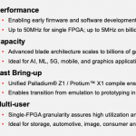
For multi-user usage, users can partition down to a single FPGA (with up to 48 users per rack) as appropriate, delivering 20M ASIC gates running up to 50MHz. Or you can take over multiple racks (1B gates per rack) running at around 5MHz. Speeds here are for automated partitioning; with manual optimization I was told you can double performance.

Frank Schirrmeister (needs no introduction) stresses that X1 extends the range of the S1 prototyper. You can and should continue to use your S1 desktop systems as you have been using them. X1 extends the reach of prototyping by 64X on the same underlying S1 architecture. Cadence supports all of this with a brand-new Pathfinder partitioner and strategies designed to optimize pin-multiplexing through SERDES, LVDS, etc. for FPGA-to-FPGA connectivity. Manual optimization includes the usual partitioning and inter-FPGA logic options, also ability to substitute native interfaces such as PCIe for design IPs. Blade and rack partitioning through cabling are supported by a GUI to configure and check setup.

Very importantly, Cadence have put a lot of work into accelerating bring-up (for X1 and S1 since these have a common front-end). Analysis on multiple customer designs shows Protium bringup 80-90% faster than comparable systems,. This reduced in one example a bringup time of 20 weeks down to 2 weeks, making early stage firmware/software regression and debug much more practical. For system/in-circuit validation, these systems continue to support Cadence’s rich portfolio of SpeedBridges, which has to be a real plus in hardware-in-loop (HIL) testing requirements found in automotive testing, as one example.

For hardware debug you can use Indago, Verdi or similarly-capable debuggers. As you shift to firmware/software debug you’re more likely to be using Lauterbach, the ARM Keil debugger or other tools of that nature. Juergen told me that they know a variety of debug tools will be needed so they put a lot of debug investment into data capture and creation, also control of the debug system for backdoor memory access, starting and stopping the clock, all the features that have to be efficiently supported by the prototyping hardware, whatever debugger you use at any given stage.

More and more verification capability is moving to datacenters and to the cloud, following trends in software in general, making for better utilization of in-house capital investments and much easier scalability to handle peaks in the cloud, or longer term to rebalance in-house investment strategies. Protium X1 looks like a very logical step along that path. You will be able to learn more about the X1 at DAC, also you can check out the features and specs HERE.