webinar banner2025 (1)

IP Lifecycle Management and Permissions

IP Lifecycle Management and Permissions
by Daniel Payne on 07-29-2019 at 10:00 am

Percipient IPLM

My first professional experience with computers and file permissions was at Intel in the late 1970s, where we used big iron IBM mainframes located far away in another state, and each user could edit their own files along with browse shared files from co-workers in the same department. I saw this same file permission concept when using computers from DEC, Wang, Apollo, Sun, Solbourne, HP and others. Even my MacBook Pro computer has an OS based upon Mach OS, derived from BSD UNIX, so it’s very familiar to me when using the command line. SoC designers today are using Linux and UNIX-based computers either on their desktop, network, private cloud or public clouds, and they all have file permissions to help organize how teams share files while the IT group can administer policies.

For an IP-based SoC we need something to help us manage access and track usage of all of those IP blocks, thus the concept of IP Lifecycle Management (IPLM) tools arose and is served by enterprise solutions vendors like Methodics. Using an IPLM approach means that there is one, centralized repository for an SoC design, so that users can get a Bill of Materials (BOM) and know where each IP block is being used. Just like files have permission, each IP block has permissions with IPLM as a way to bring order and allow the IT group to assign roles like Read access or Write access to trusted engineers on a team.

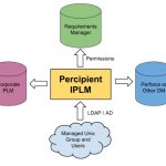
An ideal IPLM system should be a single source of truth, managing IP, related databases, corporate PLMs, requirement managers and even bug trackers. It turns out that Methodics does have an IPLM tool called Percipient that aims to fulfill these ideals.  Let’s take a quick look at how the Percipient IPLM approach connects to low-level files, requirements manager, Data Management (DM) systems and PLM tools:

Percipient

Just like UNIX allows you to set individual file permission of Read, Write, Execute and Owner; with Percipient you can decide to assign Read, Write or Owner permissions to users or groups of users for each IP block within the company. In Unix you’ve already defined the concepts of Users and Groups, so that info can be re-used within Percipient to enable permissions for each IP block.

Percipient also has the concept of hierarchy, meaning that one IP block may itself contain one or many lower-level IP blocks, so you get to define the IP permissions per user and group. If your team has contractors, then it makes sense that you restrict their access to any sensitive IP block details. An admin using Percipient can also grant permissions to all IP hierarchy using a single command, so managing IP access can be quickly updated as your project dynamically changes.

IP permissions are set by knowing who is working on a project, and also which IPs are being used on a project. Engineers that are working on a project will be part of the same UNIX group, so Percipient synchs with your LDAP/AD system to know which engineers belong to each group. To add a new engineer to your project or remove an engineer just update their UNIX group.

Once Percipient knows each UNIX group that are being used, then you can define which IP  blocks are assigned as Read, Write or Ownership permission. The IP hierarchy permissions are also defined by an admin either all at once, or by hierarchy level. You define group membership using UNIX and it gets synced within Percipient, so it’s always up to date.

Each IP block with multiple users in different project hierarchies can have multiple permissions with different project groups, so it’s quite flexible to meet your unique project needs.

With Percipient there’s a convenient, centralized place to to view both project and file permissions. Percipient consistently applies permissions into the underlying DM system, whether that is a Perforce IP or another DM. Engineers only see and can modify the specific IP blocks that permission has been granted for.

IP blocks that are changed or re-used in different contexts have their file permissions always in-sync with the DM tool.

Permission management for bug tracking tools like Jira, or a Wiki manager such as Confluence can both be performed by Percipient, extending the utility of a centralized approach.

Let’s say that you wanted to find out the project BOM along with all permissions attached to each IP contained in the BOM. With the Percipient tool there’s a RESTful public API, and here’s an example using the command line, along with the output results:

Results of using the RESTful API

The results tell us that the users of group “proj_yosemite” have Read permission to the IP, and that user “sasha” has Read, Write and Owner permissions to the IP.  Using this API makes it straight-forward for CAD engineerings to integrate Percipient with other software tools that use permissions.

Summary

Both operating systems and IPLM systems have come a long way over the years, making the life of SoC engineers a bit easier by using automation to help manage hierarchy in IP blocks, along with synching up with DM, project requirements and bug tracking tools. Your BOM can now be maintained in a single tool, along with managing all of the permissions to each IP. For more details there’s a 10 page White Paper available at Methodics web site.

Related Blogs


Real Men Have Fabs Jerry Sanders, TJ Rodgers, and AMD

Real Men Have Fabs Jerry Sanders, TJ Rodgers, and AMD
by John East on 07-29-2019 at 6:00 am

In 1977 I made a job change:  I took a job at Raytheon Semiconductor.  Raytheon was on Ellis Street next door to the Fairchild “Rust Bucket”.  In the early days, they shared the same parking lot so my commute didn’t change much, but my outlook on life changed a bunch.  I had mostly enjoyed my days at Fairchild, but I hated every single day I spent at Raytheon.

Then, in 1979,  I got a break!  Gene Conner (a great boss and AMD’s first product engineer)  offered me a job as product manager of AMD’s Interface product line.  I jumped on it!!!  Wow.  It was like dying and going to heaven.  Within a few days Gene taught me the most important thing that you had to understand if you were going to be a manager at AMD.

People first.  Products and profits will follow.

Jerry Sanders was definitely a flamboyant guy. Some of the stories you may have heard are probably overstated,  but he was flamboyant!  He was also very sensitive to the needs and feelings of the people who worked there.  Jerry hated the idea of layoffs.  Layoffs are very different from firings.  Someone gets fired if they don’t do their job well.  It seems harsh, but sometimes that has to happen.  With layoffs,  though, people who are doing their job well get let go.  We all hate that.  Jerry particularly hated it. Layoffs were a common part of the Silicon Valley culture at the time (See my week #7.  Layoffs Ala Fairchild). Jerry didn’t want AMD to be like that.  He instituted a no-layoff policy at AMD.  At first it was an informal policy.  Later, he had it written in the company’s policy manual.  For 17 years he stuck to it.  If things weren’t going well temporarily, Jerry’s view was  – hold on to the people and let the earnings suffer.  Not the other way around. That was unheard of in Silicon Valley semiconductor companies.  It made people want to work at AMD. The great recession of 1984 came.  We dropped into a loss position.  Our spending was too high. Our sales too low.  The cash balance wasn’t strong.  At an executive staff meeting we were hashing out what we could do about it.  The subject of a layoff came up.  Several execs were pushing for a layoff.  Jerry went apoplectic. He banged on the table yelling,  “I’m not going to preside over the dismantling of my life’s work.”  Jerry was always a good “quote machine”,  but that one in particular will stick with me forever.

(Unfortunately, by the time 1986 rolled around we were still in a loss position and the cash balance was running dangerously low.  We were forced to abandon the policy.)

In 1980 we had a very good year. Jerry wanted to spread the wealth.  He decided to hold a raffle.  The winner of the raffle was to get a house!   Yes.  The title to a real house here in Silicon Valley! Even back in 1980, production workers generally couldn’t afford their own houses.  The raffle was held, as I recall, on a Saturday night.  Early Sunday morning Jerry, accompanied by a Channel 7 TV crew, went to the home of the winner (A Fab worker named Jocelyn Lleno who didn’t have any idea that she had won) and knocked on the door.  When she answered the door wearing her bathrobe,  he told her,  “Hi.  I’m Jerry Sanders.  I came here to tell you that you won the raffle.  You’ve won a house here in Silicon Valley.”  She was blown away!!!  (Actually, the prize was $1000/month for 25 years.  Hard to believe, but in those days that was enough to buy a very nice house)

Once at a black tie dinner event for AMD executives and their wives,  I was assigned to sit next to Jerry at dinner.  My wife Pam sat directly to his right.  Jerry knew that Pam owned a dance studio (she still does).  He asked her how the studio was going.  It happened that Pam was about to take a contingent of dancers to Russia, Poland, and the Ukraine for three weeks as part of an exchange program – a cadre of Russian dancers had just visited Silicon Valley.  It was expensive to take all those dancers to Russia and nobody had figured out how they were doing to pay for it.  So Pam  — extrovert that she is – responded with something like, “Well.  I’ve got a problem.  I don’t know how I’m going to pay for this Russian exchange.  Can you help?”  As I crawled out from under the table, I saw Jerry reach into his jacket pocket.  He pulled out a check book and wrote out a personal check for $1000.

I first met TJ Rodgers in 1982 when he worked at AMD.  Shortly after that,  he left AMD to found Cypress Semiconductor.  In 1992 plus or minus a year or two Valerie Rice, a writer for the San Jose Mercury News, was interviewing TJ.  The fabless concept hadn’t yet taken over the world,  but it was making inroads.  Valerie asked TJ what he thought about the fabless model.  I love TJ Rodgers!  He was one of the old guard CEOs (As I was).  He believed in Fabs,  device physics, and transistor level circuit design (Things have changed.  See my upcoming week #15.  The Decade that changed the industry.)  Valerie tried to help by summarizing what he had said.  “So, you’re essentially saying that real men have fabs,  right?”  That was a play on the title of a book that was very popular back in the day.  Real Men Don’t Eat Quiche.  TJ jumped on it.  “Exactly!!!”  Jerry Sanders read that line and loved it!  Later that year he was the lunch speaker at the Instat Conference (Jack Beedle’s annual semiconductor conference that was attended by virtually all the big brass in the business).  The high point of his talk?  In his very strongest “take charge of the room and lay down the law” style:  “Now hear me and hear me well.  Real Men Have Fabs!!!!”  Most of the speakers that afternoon were fabless company CEOs.  I was one of them.  Jerry’s talk sent us all scurrying back to our power points to make the necessary changes.  The Instat Conference was always fun, but that was the best one ever!!

There was something about the AMD environment that spawned CEOs.  Was it the collegial environment?  In total,  83 former AMDers have gone on to become CEOs of other tech companies.  The two who impress me the most, though, are two CEOs who were just starting their careers at AMD during the days when I was a VP there.  Jayshree Ullal and Jensen Huang.  Jayshree  (the CEO at Arista Networks)  took Arista from a fledgling company to one now valued at twenty billion dollars!  There’s a great article about her in Forbes Magazine.   Jensen (the CEO of Nvidea) has built a juggernaut, but I think of him as the best public speaker I have ever listened to.  (Actually – he’s tied with Jerry Sanders who is the greatest orator in the history of High Tech!!!).   At the typical dinner event, most of us can’t wait until the keynote speaker shuts up so that we can eat.  In the case of Jensen, though, you don’t want him to stop.  He’s just plain fun to listen to.

There was a terrific amount of camaraderie and love for the company in the early days of AMD.  A terrific spirit!  It seemed to me that it waned a bit, though, when Jerry left.  This May 8th I was invited to attend the AMD 50th birthday celebration in their new offices in Santa Clara.  It was a really well planned event.  I talked briefly with Lisa Su (The new CEO) and with a dozen or so of the present-day rank and file employees.  My takeaway?  Lisa Su is great and the spirit is back.

Jerry Sanders was CEO of AMD for 33 years.  TJ Rodgers was CEO of Cypress for 33 years.  The industry lost a lot when they retired!  I miss them!!!

Next week:  The IBM PC

See the entire John East series HERE.

Pictured:  Jerry Sanders


Taking the Pain out of UVM

Taking the Pain out of UVM
by Daniel Nenni on 07-29-2019 at 5:00 am

If you are interested in gaining a deeper understanding of the many ways you can leverage the Universal Verification Methodology (UVM), Breker Verification Systems has gone to a lot of effort to put that information at your fingertips.

A technical subcommittee of Accellera voted to establish the UVM in December 2009. UVM was based on the Open Verification Methodology (OVM-2.1.1), a verification methodology that had been developed jointly in 2007 by Cadence Design Systems and Mentor Graphics. In February 2011, Accellera (a non-profit organization) formally approved a Reference Guide, a SystemVerilog class library, and a User Guide. UVM was, to a large part, based on the eRM (e Reuse Methodology) for the e Verification Language developed by Verisity Design in 2001. Accellera was likewise was based on a merger of previous standards organizations. Most standards are adopted after the fact by a dominant format already in use; standard organization share that trait as well. Accellera’s stated mission is to provide a platform in which the electronics industry can collaborate to innovate and deliver global standards that improve design and verification productivity for electronics products. And they have been at it for a while. If you have been to a DVCon event, that is run by Accellera.

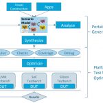
The Universal Verification Methodology (UVM) has proven to be highly effective in establishing common testbench coding methods, enabling reuse and improving the comprehension of tests. However, the methodology still has limitations that particularly impact complex block verification. The Accellera Portable Stimulus Standard (PSS) allows for many of these limitations to be eliminated, while still leveraging existing test benches, thereby not wasting legacy effort. PSS, through the Breker tools, enables a white-­‐box approach to test authoring, allows complex multi-­‐threaded, synchronized sequences to be generated from single scenarios, automatically provides scoreboard checks and coverage models, and generally improves test reuse and verification use models. The paper they have developed demonstrates how PSS may be leveraged in UVM environments to realize these and other advantages.

This thorough 24-page white paper will be given to attendees for Breker’s upcoming webinar, Eliminating Hybrid Verification Barriers Through Test Suite Synthesis. This webinar is the second the SemiWiki Webinar Series will be held at 10:00 am (PDT) on August 24, 2019. The primary speaker will be Aileen Honess. Aileen has more than 20 years of experience teaching, mentoring, and leading hardware verification projects across a variety of disciplines, companies, and continents. She is an expert in UVM and has recently been assisting those who are modernizing their verification methodology by adopting portable stimulus and portable specifications. To register for the event, click here, and be sure to register using your work email address.

As a special bonus, Breker intends to also give attendees a new white paper that is still in development. The working title for that white paper is ‘Finally, Thorough SoC Verification – Leveraging PSS Test Suite Synthesis for High-Coverage SoC Testing.’ This paper takes a deep dive into many of the topics that will be discussed at the webinar, so sign-up today.

About Breker Verification Systems
Breker Verification Systems is the leading provider of Portable Stimulus solutions, a standard means to specify verification intent and behaviors reusable across target platforms. It is the first company to introduce graph-based verification and the synthesis of powerful test sets from abstract scenario models. Its Portable Stimulus suite of tools is Graph-based to make complex scenarios comprehensible, Portable, eliminating test redundancy across the verification process, and Shareable to foster team communication and reuse. Breker’s Intelligent Testbench suite of tools and apps allows the synthesis of high-coverage, powerful test cases for deployment into a variety of UVM to SoC verification environments. Breker is privately held and works with leading semiconductor companies worldwide. Visit www.brekersystems.com to learn more.

Also Read

WEBINAR: Eliminating Hybrid Verification Barriers Through Test Suite Synthesis

Breker on PSS and UVM

Verification 3.0 Holds it First Innovation Summit


SiFive Fosters RISC-V Collaboration and Education in India and Bangladesh Via Symposiums, Tutorials and Workshops

SiFive Fosters RISC-V Collaboration and Education in India and Bangladesh Via Symposiums, Tutorials and Workshops
by Swamy Irrinki on 07-27-2019 at 4:00 am

Last year we hosted several SiFive Tech Symposiums in India to help promulgate the RISC-V ecosystem in the region. The enthusiastic reception from those in industry as well as students and faculty at India’s most esteemed universities was inspiring. This July and August, we’re bringing the SiFive Tech Symposium back to India, and also visiting Bangladesh. Our goal remains to foster the RISC-V ecosystem and to help prepare university students for entry into a workforce where RISC-V is heavily utilized. We have industry-centric symposiums planned in New Delhi/Noida, Pune, Bangalore and Hyderabad; and university-centric tutorials and workshops planned for Chennai, and Dhaka in Bangladesh. Attendance at all events is free, but registration is required. Here is a glimpse of what’s happening in each city. You can also visit the https://sifivetechsymposium.com to learn more about these and other SiFive Tech Symposiums being held throughout the world.

New Delhi/Noida Symposium – Monday, July 29

With Western Digital as our co-host, this event will feature presentations by Krste Asanovic, chairman of the RISC-V Foundation and co-founder and chief architect at SiFive; Western Digital; Ministry of Electronics & Information Technology, government of India; Silicon Catalyst; CircuitSutra Technologies; Computer Science and Engineering Department at IIT Delhi; and many more. There will also be a tutorial on SiFive’s Core Designer, which will demonstrate the ease and speed at which a customized CPU core can be built. To view the full agenda and to register to attend, please visit https://sifivetechsymposium.com/agenda-delhi-noida/

Pune Symposium – Wednesday, July 31

With Western Digital as our co-host, this event will feature presentations by Krste Asanovic, chairman of the RISC-V Foundation and co-founder and chief architect at SiFive; Western Digital; Hardware Design Group at the Center for Development of Advanced Computing (C-DAC, India); Silicon Catalyst; IoTIoT.in; and many more. There will also be a tutorial on SiFive’s Core Designer, which will demonstrate the ease and speed at which a customized CPU core can be built. To view the full agenda and to register to attend, please visit https://sifivetechsymposium.com/agenda-pune/

Bangalore Symposium – Thursday, August 1

With Microchip and Western Digital as our co-hosts, this event will feature presentations by Krste Asanovic, chairman of the RISC-V Foundation and co-founder and chief architect at SiFive; Microchip; Western Digital; QuickLogic; Silicon Catalyst; Morphing Machines; and many more. There will also be a tutorial on SiFive’s Core Designer, which will demonstrate the ease and speed at which a customized CPU core can be built. To view the full agenda and to register to attend, please visit https://sifivetechsymposium.com/agenda-bangalore/

Chennai Tutorial/Workshop – Saturday, August 3

With IIT Madras as our co-host, this academic-centric event will feature a presentation by Krste Asanovic, chairman of the board of the RISC-V Foundation and co-founder and chief architect at SiFive, and other industry veterans. There will be a tutorial on RISC-V cores and software, and a hands-on workshop where attendees will configure their own custom RISC-V core. This event presents a unique opportunity to network with RISC-V luminaries and solution providers. To view the full agenda and to register to attend, please visit https://sifivetechsymposium.com/agenda-chennai/

Hyderabad Symposium – Monday, August 5

With Western Digital as our co-host, this event will feature presentations by Western Digital; SRiX; CircuitSutra Technologies; and many more. There will also be a tutorial on SiFive’s Core Designer, which will demonstrate the ease and speed at which a customized CPU core can be built. To view the full agenda and to register to attend, please visit https://sifivetechsymposium.com/agenda-hyderabad/

Dhaka, Bangladesh Tutorial/Workshop – Aug 26

With the University of Dhaka and Ulkasemi as our co-hosts, this academic-centric event will feature presentations by executives at SiFive, a talk by a faculty member at the University of Dhaka, a tutorial on RISC-V cores and software, and a hands-on workshop where attendees will configure their own custom RISC-V core. This event presents a unique opportunity to network with RISC-V luminaries and solution providers. To view the full agenda and to register to attend, please visit https://sifivetechsymposium.com/agenda-dhaka/

We look forward to seeing you!


SemiWiki Webinar Series: Who Wants to do a Webinar?

SemiWiki Webinar Series: Who Wants to do a Webinar?
by Daniel Nenni on 07-26-2019 at 10:00 am

Webinars have been a popular form of communication since even before SemiWiki existed and they are a mainstay in today’s fast-moving semiconductor ecosystem.

In the past, SemiWiki has assisted with more than a hundred webinars. Today SemiWiki can do a complete webinar from start to finish using the GotoWebinar software. SemiWiki bloggers can assist with content creation and promotion, plus we have more than 8 years experience perfecting the webinar recipe. This brings us to the upcoming SemiWiki Webinar Series.

Thus far we have more than a dozen webinars in process. When the registration page goes live it will appear on the front page SemiWiki Webinar Series widget, which is also included in the weekly SemiWiki newsletter. More detailed information about the webinar will be available via blogs before the webinar goes live and after the webinar replay is available so stay tuned.

Here is what we have scheduled thus far:


GPU-Powered SPICE: The Way Forward for Analog Simulation

Eliminating Hybrid Verification Barriers Through Test Suite Synthesis

Avoiding CDM (Charged Device Model) ESD Failures

Fabless: The Transformation of the Semiconductor Industry

eFPGA – “What a great idea! But I have no idea how I’d use it!”

Ensuring System-level Security Through Hardware/Software Security Verification

Flexible, Multiprotocol IO’s in 7nm FinFets

The Brave New World of Customized Memory

VLSI Design Methodology Development

Enabling Efficient Engineering Infrastructure: Streamline your development resources and increase engineering productivity

Desinging Complex SoCs and Dealing with Multiple File Formats?

Please notice this is a mix of company sponsored and blogger specific webinars. For example, Paul McLellan and I will do a webinar on our 2019 updated version of  “Fabless: The Transformation of the Semiconductor Industry”. People who attend the webinar will be able to download a PDF copy of the book. Tom Dillinger will also be doing a webinar on his new book “VLSI Design Methodology Development” published by Prentice Hall. Other SemiWiki bloggers will be joining in the SemiWiki Webinar Series later this year as well.

One thing I wanted to consider is opening up the webinar series to SemiWiki members who have something personal to promote or something semiconductor to say for the greater good of the industry that we all know and love. Or if you have a topic that you would like us to cover in a webinar we can consider that as well. Please leave comments here or email me directly on SemiWiki.

Back to the scheduled webinars, participating companies are (in order on the widget): Empryean, Breker, Magwel, Flex Logix, Tortuga Logic, Concept Engineering, sureCore, Methodics, and Analog Bits with many more to come.

In the past 8 years and 7 months SemiWiki.com has attracted more than 3,094,662 users from 24,725 unique domains. We have published more than 6,530 blogs that have garnered more than 19,054 comments.  SemiWiki has also published 7 books (with 2 more coming this year) and dozens of white papers and reports.

SemiWiki is called a boutique media channel since we are semiconductor professionals who can write versus journalists. Our audience is worldwide with the top ten viewing countries: United States, India, Taiwan, Germany, United Kingdom, France, South Korea, Canada, China, and Japan.

While this was my initial concept, SemiWiki has developed and succeeded beyond all expectations as a collaboration between semiconductor professionals around the world, absolutely.

Thank you all again for being part of SemWiki’s amazing success and I hope to see you on a webinar real soon.


Chapter 3 – Moore’s Law is Unconstitutional!

Chapter 3 – Moore’s Law is Unconstitutional!
by Wally Rhines on 07-26-2019 at 6:00 am

(Adapted from a presentation first given under this title in 1989 and subsequently expanded in presentations over a period of nearly thirty years)

In 1965, Gordon Moore, then R&D Manager for Fairchild Semiconductor, published a paper in “Electronics” magazine predicting the trend for semiconductors in the next ten years.  He showed a graph of the number of components in the largest chips in each of the last four years that followed a straight line when plotted with a Y-axis that was the base two logarithm of the number of components (transistors, capacitors, resistors or diodes) and the horizontal axis was time.  The number of components had doubled every year (Figure 1). This graph became known as “Moore’s Law” and has been extrapolated for more than fifty years.  It is not a “law”.  It is an empirical observation that became self-fulfilling after some adjustments.

Figure 1. First presentation of Moore’s Law in 1965

Ten years later, in 1975, Gordon Moore revised “Moore’s Law”, saying that the doubling of transistors per chip was now occurring every two years, instead of every year. Then, in 1997, Gordon Moore revised “Moore’s Law” once again, showing that the doubling of transistors was now occurring every 18 months.  These repeated revisions affirm that “Moore’s Law” was not actually a law of nature but an interesting, if temporary, phenomenon. In science and engineering, we have laws that predict outcomes when variables change, like the first and second laws of thermodynamics, Newton’s laws of motion or Maxwell’s equations.  They don’t change over time, unlike Moore’s Law (Figure 2). Even Dr. Moore pointed out, in his ISSCC keynote in 2003, that “no exponential is forever”.

Why did “Moore’s Law” take on such significance and work so well, despite the adjustments in time scale?  The answer is that “Moore’s Law” is based upon an actual law of nature called the “learning curve” (See Figure 1 in Chapter 1). Learning curves have been used over the last hundred years to predict the future cost per unit of products as diverse as airplanes, beer and transistors. They were used strategically by Texas Instruments in the 1960’s to “forward price” new semiconductor components in order to achieve a desired future market share and profitability.

The learning curve and Moore’s Law are actually the same when two conditions are met.  These are:  1) If most of the cost reduction for semiconductor chips comes from shrinking feature sizes and growing wafer diameters and 2) If the cumulative number of transistors manufactured by the semiconductor industry increases exponentially with time.  If these two conditions are met, then Moore’s Law and the learning curve become straight lines that predict the same trend (Figure 3).

If “Moore’s Law” is based upon a real law of nature, i.e. the learning curve, then why did it have to be adjusted from one year to two years and then back to eighteen months?  The answer comes from assumption number two above and is shown in Figure 4. Even though the number of transistors shipped each year has grown exponentially through most of the history of the semiconductor industry, there was a period when growth slowed and then later returned to the exponential trend.  That change in growth rate caused “Moore’s Law” to increase from one to two years and then back to eighteen months. Because the learning curve is a log/log graph, exponential growth of the cumulative number of transistors produces a straight line with time as well as with the cumulative number of transistors. Unlike Moore’s Law, the learning curve works well even if the exponential growth of units deviates.  Moore’s Law uses time as its horizontal axis so linearity is assured only if cumulative transistor growth is exponential.

Today, many people worry that the inevitable end of Moore’s Law will leave us with a stagnant semiconductor industry with no guideposts to drive new silicon technology directions. Fortunately, these people need not worry.  The learning curve is valid forever (when measured in constant currency, corrected for governmentally-induced inflation) as long as free market economics prevail, i.e. negligible trade barriers, no regulatory price controls, etc.

Figure 5 shows a learning curve for the electronic switch measured as revenue per MIP, beginning with vacuum tubes and progressing through germanium and quickly transitioning to silicon.  We use industry revenue for the vertical axis, instead of cost, because the data is more readily available but the two variables should be surrogates for one another.  The horizontal axis is the cumulative number of transistors shipped throughout history.  That number has been available from the Semiconductor Industry Association, as well as from other semiconductor analysts, for decades.

Of course, the learning curve for electronic switches doesn’t care whether the cost reduction is achieved with mechanical switches, vacuum tubes, transistors or even carbon nanotubes in the future. The learning curve is technology independent if a more generalized unit than transistors is measured. We therefore have a metric to track when the further improvements in cost or power are so difficult with silicon that we have to consider an alternative like carbon nanotubes or bio-switches. The important result of this information for the electronics industry is that the death of Moore’s Law doesn’t lead to random, unpredictable trends in semiconductor technology.  We have a road map.  As long as we can measure the growth rate of transistor shipments, we will know the cost or revenue per transistor of the semiconductor industry, or vice versa.

Figure 2. Moore’s “Law” evolved over time

Figure 3. Learning Curve and Moore’s Law are the same under certain conditions

Figure 4. Growth in cumulative number of transistors has not always been exponential with time

Figure 5. Cost per Function, or per MIP, transcends the transistor era

Read the completed series


The Wild, Wild SEMICON West TechTALK – Joe Costello Speaks Out

The Wild, Wild SEMICON West TechTALK – Joe Costello Speaks Out
by Randy Smith on 07-25-2019 at 10:00 am

On July 9, 2019, I attended the TechTALK session hosted by Dave Kelf of Breker Systems, Inc. titled, “Applied AI in Design-to-Manufacturing.” I was happy to hear what Dave had put together for this since it is a topic I am keenly interested in and because I have known Dave personally through music and charitable activities we have worked on together.

Dave’s intro was brief when he gave way to his first speaker Aki Fujimura, Chairman, and CEO of D2S, Inc. Again, I was having the pleasure of listening to a good friend as Aki and I were two of the co-founders of Tangent Systems when we were both relatively fresh out of college. Back then, we were working together on timing-driven place and route. We have both broadened technically since then. Aki has immersed himself in the manufacturing side of semiconductors while founding D2S in 2007. Aki’s title was a straightforward description of his talk, “Everything Needs a Digital Twin in the Deep Learning Era.” As I understood it, since there are relatively few defects to be found in actual mask designs, it is complicated to train a deep learning neural network on how to find them. Aki’s proposed solution is to create a digital twin, a simulated version of the real wafer or mask. At the same time, I thought it was deep, weird, and brilliant. I often had trouble keeping up with Aki and Steve Teig (another Tangent co-founder) when we worked together as they are both outstanding engineers. The concept of a digital twin will be something I want to follow through and study more.

Next up was Jan Rabaey of both UC Berkley and IMEC. Jan spoke about “The Cognitive Edge.” We have heard multiple interpretations of what Cloud and IoT mean for a few years now. To me, the term most inconsistently used has been the Edge. What Jan adeptly pointed out is that there are a huge number of sensors and other devices in the world, generating an overwhelming amount of data. It is neither practical nor reasonable to send all of that data to “the Cloud” for processing. I appreciated Rabaey’s presentation, and I intend to talk much more about “the EDGE” in some upcoming blogs. The point here is adding intelligence at the edge of the IoT network is required because there is far too much data to send everything to the cloud. It is impractical and inefficient. What to do about it? That will be for several future blogs.

Finally, we get to the entertainment portion of the event, Jim Hogan’s panel titled, “Are we Experiencing a Renaissance in Chip Design and EDA?” From an investment point of view, EDA has seen a decrease in start-up investment since Mike Fister told the world Cadence was not going to rely on buying start-ups anymore in 2004. The statement was not prophetic because Cadence indeed completed some very significant acquisitions after that. But in the long run, it was self-fulfilling prophesy because investors started walking away from a market where successful exits were going to significantly harder to achieve given the drop in the competitiveness that would happen with Cadence as a buyer of EDA start-ups. Still, there has been a lot of new technology coming out of a smaller number of EDA start-ups, and they are affecting the EDA marketplace substantially (see Verification 3.0). There was also a strong panel of experts not from the EDA Big 3 there to discuss it.

The panel, which of course was moderated by Jim Hogan (Vista Ventures) consisted of (alphabetically) Simon Butler (Methodics), Joe Costello (Montana Systems), Simon Davidmann (Imperas), Adnan Hamid (Breker), and Doug Letcher (Metrics).   Jim’s premise, which was not refuted by the panel, was that three macro trends were powering this renewal in EDA:

  1. A new computing platform – infinite scalable compute capacity in the cloud along with cloud-native development tools like GitHub and Kubernetes, which enables a new SaaS business model that lets customers purchase exactly the amount of software cycles they need
  2. A customer demand for much higher simulation throughput driven by the increased size and complexity of chip design, coupled with high tape-out costs which means one must have the highest verification coverage to avoid any test escapes
  3. A new chip design opportunity – application or domain-specific processors that coupled with the cloud platform will enable startups and system companies to build specialized processors rather than the handful of giant companies building the enormously expensive general-purpose processors.

Each of these business leaders spoke on these premises supportively for a while before Joe Costello lit the fuse and declared that the big EDA’s were slowing this whole thing down by dragging their feet on truly addressing cloud-based licensing models. We need to remember that Joe was leading Cadence when they moved from perpetual licenses with maintenance fees to time-based license fees. Then, he saw what he felt his customers needed, he did it, and the rest of the industry followed. The issue today is how to provide an opportunity to scale compute power and licenses on an as-needed basis – to only pay for what you use on-demand. In Joe’s opinion, the EDA industry is not moving very quickly to this new model, or at least, the big EDA companies are not.

I have not heard much push back from Joe’s remarks, although there were many people in attendance. Maybe the conversation will start in the forum below this article? Feel free to post your remarks below.

As was mentioned above, Dave Kelf is VP, Marketing at Breker Systems. Breker Systems is holding a webinar in August titled “Eliminating Hybrid Verification Barriers Through Test Suite Synthesis.” You can read the blogabout the webinar here, or go straight to the registration page.


5G and V2X

5G and V2X
by Bernard Murphy on 07-25-2019 at 5:00 am

Amid the glamor of autonomous vehicles and hot new ADAS features, communication between vehicles and other vehicles, pedestrians, cyclists or infrastructure, generally labeled V2X, doesn’t get as much press, perhaps because adoption is still pretty early or because it’s technology under the hood (quite literally) and therefore not as immediately glamorous as other advances. That’s a shame because applications of V2X are likely to have important impact in safety and convenience long before full autonomy becomes a reality.

(Image Source: Synopsys)

Applications

Consider these potential applications of V2X. In communication between vehicles it can augment existing methods to help with left-turn assistance (for those of us driving on the right) emergency braking warnings and improved situational awareness at intersections. Extending Waze concepts, it can control or suggest speed adjustments to account for traffic congestion, also update your GPS map with real-time updates on lane closure and highway construction activity. V2X in some form is essential to support over-the-air (OTA) software updates for the now-extensive range of software-driven systems in your car, from map updates to bug fixes to security updates and more.

One really nice capability could be see-through vehicles. If your car can tap into the front-facing camera of that giant truck in front of you, you’ll be able to see what’s ahead of that truck. Kind of important if you’re tailgating and traffic ahead of the truck has come to a stop. Or if you want to pass but can’t see around the truck.

Another very interesting application is in support of platooning. This is a technique in which trucks and/or cars drive in coordinated groups. Platooning can reduce congestion since such groups can be more closely spaced than would be possible if they had to allow for human reaction times. The primary intent behind this idea is in support of self-driving vehicles on automated highways. This might be how autonomy takes off, long before it becomes universal. Reading a book or napping while you’re on a highway could be a reasonably near-term objective if we can implement the V2X infrastructure in cars and on the highways to support this. (There’s still a question of whether the lead vehicle needs a human driver. And how you exchange leads when the current lead wants to leave the platoon. But this still seems closer to feasible than grander goals.)

Technologies – Wi-Fi and Cellular

The ideal communication technology in support of V2X is a little contentious. Clearly any such technology must be extremely reliable under a very wide variety of conditions (weather, and interference from other EMI sources) and it must guarantee very low latency. You really don’t want to see a “buffering” spinning wheel in any of the applications I just described.

Wi-Fi advocates have made a strong case that Direct Short Range Communication (DSRC), a subset of 802.11, is the real candidate for V2X. Work on this standard goes back a long way but it seems compelling need is only now starting to catch up. Nevertheless it is the prescribed standard in the US and the NHTSA has already started the process for a mandate that all cars in the US come equipped with DSRC.

However – the 3GPP standards group responsible for cellular standards is a relative late-comer to this domain but has been working hard on ultra-reliable low-latency communication, known as C-V2X, as one of the principal components of 5G. This supports 1ms latency end-to-end, in compliance with the NHTSA requirement, it provides improved reliability and it support bandwidth of up to 20Gbps, allowing for high-fidelity streaming if needed. Further, C-V2X seems to have a 2X+ range advantage over DSRC, meaning it will require less small/pico-cell stations to support a given area. Finally, chips and modules are expected to become available this year and to appear in vehicles in 2020.

(Image Source: Synopsys)

What Next?

Now the US Department of Transportation are hedging their bets on that mandate I mentioned earlier. When their review started, DSRC was the only option. Now C-V2X looks like a strong contender. Heidi King, deputy administrator at NHTSA has stated that “USDOT remains technology-neutral relative to communications protocols that support V2X technology.”  Some companies and region have already adopted DSRC for some applications (eg Cadillac, Singapore, Utah), C-V2X for some others (Ford, Las Vegas). It’s a race but important to realize that the race has barely started.

If I had to bet, I’d go with the cellular solution as the long-term winner. This has nothing to do with technology. My bet is based on infrastructure cost of ownership and dependability of support. Any Wi-Fi solution will demand wide deployment of access points, plus the back-haul from those access points to gateways, etc. Who is going to pay for and maintain that infrastructure – local government (unlikely) or new private ventures? Do we have to expect unreliable support until those private ventures mature? We already have matured companies vested in providing wireless support locally and worldwide. Not that they’re perfect or can’t improve but building on that existing business and physical infrastructure makes more sense to me than launching new businesses to support a new physical infrastructure.

Key enablers of C-V2X technology are obviously the 5G radio, SoC integration and other IP components required to complete a 5G C-V2X interface. Since such solutions must be certified to ISO 26262 standards, integrators need not only the right components from their IP supplier but also confidence in their capability, depth and track record in providing ISO 26262 safety packages and certification. The right choice must meet functionality, performance, quality, and reliability levels in down to the most aggressive FinFET feature sizes. You can learn more about the Synopsys Automotive IP Segment view of this domain HERE and read more about how they are supporting design in this area HERE.


#DAC56 – Optimizing Verification Throughput for Advanced Designs in a Connected World

#DAC56 – Optimizing Verification Throughput for Advanced Designs in a Connected World
by Daniel Payne on 07-24-2019 at 10:00 am

Cadence, DAC 56, Wednesday

It was the final day of DAC56 and my head was already spinning from information overload after meeting so many people and hearing so many presentations, but I knew that IC functional verification was a huge topic and looming bottleneck for many SoC design teams, so I made a last-minute email request to attend a luncheon panel discussion featuring some tier-one companies, like:

Fellow-Oregonian Brian Bailey was the panel moderator, and he did a fine job keeping the discussion focused and moving along. Brian started out by noting that 20 years ago the IC world was simpler with Verilog being used, code coverage goals as metrics and RTL entry, however today there are many languages to consider, plenty of EDA tools to choose from, formal techniques, emulation becoming common, and new standards like PSS.

Panel Discussion

Q: What does verification throughput mean to you?

Tran – Yes, we do have an infinite verification challenge. Each of our design cycles is for about 9-10 months, and this time frame doesn’t change much each new project. How efficiently can I verify, are these new cycles finding any new bugs? A faster speed of verification helps us, but uncovering more bugs is what we really need.

Raju – we need a more holistic picture from design verification to post-silicon. There are issues like build, resource utilization, run speed, and time to root cause. How fast can this HW fix get in (Build)? How fast are jobs launched? Are testbenches running effectively? For debug time, we want to know how fast can I find and fix a bug. These four verticals are the focus of our work.

Dale – how many jobs can I submit into emulation, iterate and debug, finding RTL bugs? Is build, run, testbench, AI scripting to triage any failures. We don’t have QA engineers wait for jobs to finish, so we need to make their time more productive.

Paul – you can only optimize what you can measure. Raw throughput metrics like time to see waveforms are important. Higher order metrics are time to root cause of bugs. We do have a cockpit to pull all of these analytics together in one place.

Q: How do different SoC designs use verification?

Dale – for GPU verification and development we have functional goals like RTL health, GPU performance, pre-validate GPU with drivers, where each team has their own test bench. Regression and debug tasks have different test benches.

Raju – we need our chips to run across multiple OSes, meeting the requirements.

Tran – across multiple products we like to reuse some parts of test benches to improve throughput.

Paul – there’s raw performance and also root cause rates, but at different levels of abstraction (transistor, gate, RTL, OS) we need to optimize throughput, then pick the right tool for the job.

Dale – as a verification engineer we just pick up the tools and use it, but didn’t think about how the tools work. Collaborating with the Paladium team I’ve learned of different approaches to get the best throughput.

Q: How do you assess each of the verification tools to use them in the right tasks?

Raju – collaborating with the EDA vendor and knowing their product roadmap helps us plan which vendor to work with.

Tran – we need help to understand the verification data that we are generating from the tools. Would like to use some ML to help us analyze our test data better.

Paul – formal is a great example that complements dynamic verification approaches. What are the test payloads gong through?

Q: Is time being spent in debug getting worse?

Raju – yes, Verification tasks and use is increasing dramatically. Debug techniques need to improve, so more automation is required. We can build more common debug approaches, and we can use ML and AI to help pinpoint verification bottlenecks.

Tran – debugging a system of systems, like verifying an autonomous vehicle is a big, new challenge. We have a lot of known unknowns to verify, it’s very complex for us to achieve.

Paul – the opportunity to use AI in the debug process is ripe, how can we guide the human to look in the best debug areas?

Dale – we have metrics to assess how verification tools help throughput, but engineers need to know tool limitations in order to be most efficient in test bench generation. Generating traces for 1 million cycles takes one day of run time, so use a different approach to find and fix the bugs.

Q&A

Q: Maxim – we use VIP and metric-driven verification approaches. But our designers and verification engineers have a different understanding of the same specs. Can you help our teams capture the specs correctly?

Raju – that’s a fantastic problem statement, because stale documentation causes differences between design and verification engineers. We’re trying to have standardized documentation requirements with frequent sign-off criteria, keeping specs up to date as design changes occur. Using PSS is going to help us document all of our requirements better.

Dale – making sure test and design specs meet the overall specs is important. Finding mistakes in interpretation of specs is important.

Paul – smart linting can catch mistakes earlier, some VIP can provide 100% coverage of known specifications.

Q: How much metric driven verification do you use?

Raju – we use functional and code coverage metrics in all verification flows to get signoff points. We have legacy coverage goals, and need to be smarter about finding and removing redundant testing.

Paul – coverage driven verification methodology is our goal (Formal, Simulation, Emulation), with a single dashboard.

Q: Are you using the right metric for your verification goals?

Raju – how can we improve our verification coverage with each tool: Formal, Simulatio, Emulation.

Q: Is there a standard way to use AI and ML, sharing across a verification environment?

Tran – AI is something very new, so we’re still learning how to use it during verification, trying to get a better understanding of our test data. We store and plot our test coverage metrics, but there’s no standard process that AI would automate.

Paul – we see lots of test data gathering going on now, and Cadence has a method to collect it, but there’s no industry standard out there for data gathering. What do you want us to do with this test data? How can we use this data improve our test goals?

Q: Is the cloud gong to help us in collecting data and applying AI for improving test?

Paul – you can do analytics anywhere.

Tran – the cloud is just a technique, the reasoning is the important point.

Paul – yes, the cloud will ensure that we gather more data.

Q:  Software in our systems is a large part of SOCs, how does that affect verification?

Raju – having verification drivers is important, getting to SW debug we often use FPGA for prototyping.

Dale – to get Android and Linux booting, we need prototyping sign-off to reach verification goals. Bugs happen between SW, HW, firmware and RTL, so we need emulation to reach our tape out goals.

Tran – to verify SW and OS we use FPGAs for prototyping, but SW verification has a lot of room for improvement.

Dale – SW developers start with virtual debugging, then eventually HW prototyping.

Paul – SW bring up is very expensive, so pre-silicon SW bring up is the goal.

Conclusion

The panelists were uniform in their replies on the topic of optimizing verification throughput, and they have an established approach to verification that now includes: formal methods, emulation, FPGA prototyping, PSS, and even ML to help wade through so many logfile results. Successful EDA vendors will continue to help automate more verification tasks in order to equip engineers in finding more bugs, quicker.


The Flash and the Taiwan ESD Seminar!

The Flash and the Taiwan ESD Seminar!
by Daniel Nenni on 07-24-2019 at 6:00 am

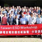
During my trip through Asia last week I attended the Taiwan ESD Workshop. Hsinchu is densely populated with some of the smartest semiconductor people in the world so it is well worth the trip, absolutely.  As it turns out ESD is one of the top concerns in semiconductor design and manufacture. The current rule based and simulation solutions are not scaling so the search is on for new ways to protect our chips from electrostatic discharge.

The DC Comics character the Flash (my personal favorite) received his super powers when he was struck by lightning in his lab. Sadly, in real life neither people nor electronic circuits are so lucky when they are hit with lightning. Even nature’s scaled down common electrostatic discharges can have devastating effects on modern integrated circuit chips. Far from imbuing them with super powers, electrostatic discharges (ESD) render chips useless, by destroying devices and melting metal interconnect, or more insidiously damaging them just enough to make it into a product that will mysteriously fail down the road.

To avoid this peril designers employ protection circuits that have to operate as fast as the Flash to intervene and prevent damage. Their ability to protect the circuit comes from having a lightning fast response to an incoming ESD event, harmlessly deflecting the high voltage current before it can cause any harm to the circuit. The actual behavior and performance of the ESD protection designed into a chip depends on many factors. Last week in Taiwan, Magwel’s CEO, Dundar Dumlugol, presented a well attended seminar on the topic of ESD protection simulation, where he talked about many of the specific factors that play a role in determining ESD protection effectiveness.

In the case of HBM, Dundar suggested that despite a few minor disadvantages, a static simulation based approach offers both high throughput and very high accuracy for ESD simulation. When done properly, static simulation can tell designers about voltage build up over devices and also parasitic resistances. It is also good at determining voltage build up over protected devices, parasitic currents in sneak paths, non-uniform triggering of parallel power clamps and non-uniform triggering in fingers of ESD devices. Finally, one of the most important pieces of information that it can provide is the result of competitive triggering between ESD devices and protected devices. This would make the Flash proud, because his mission is to protect those in danger.

Dundar also spoke about how Magwel’s ESDi, used for HBM simulation, takes advantage of reduced order modeling (ROM) to make simulation of large power and ground net resistive networks feasible. Without this approach complete simulation of all the pad pairs in a large design could take many times longer. Using their simulation approach, Magwel’s ESDi can help find the following issues:

  • Missing / undersized vias (via burnout)
  • Current crowding in metal / vias
  • Excessive bus resistance
  • Excessive voltage stress over protected devices
  • Wrong/missing ESD devices
  • ESD device burnout (It2, Vt2 limit check)
  • Imbalanced current distribution over the fingers inside ESD devices
  • Protected device triggering before parallel ESD device
  • Parasitic junction/ Bipolar triggering/ break-down
  • Protected device damage (oxide breakdown, junction / device burnout) due to voltage stress & parasitic currents

CDM is a different animal altogether, due to much faster ESD impulses and the potential for damage almost anywhere in the chip. Given this complexity, it seems like the skills of a super hero are needed to predict the outcome of an ESD event. For CDM it turns out that dynamic simulation is the best approach. According to Dundar, you still need a very accurate extracted model for the large nets in the design. This is where the charge is stored prior to a discharge event. The dynamic simulation needs to take into consideration this charge and how it flows through the wire towards the port that is zapped. The voltage drop along the connected nets caused by IR drop can damage protected devices, unless there is sufficient ESD protection designed into the circuit.

Dundar covered one example of an RF LNA circuit test chip provided by Qorvo where the lack of protection diodes caused the discharge to trigger and then pass through an output NFET, leading to its failure. Magwel’s CDMi product predicted this failure, which was confirmed in silicon. Resimulating with added protection diodes shows how the ESD current flows safely to ground. Using this method, it is possible to add only the needed number of protection diodes, preserving output performance.

To learn more register for this webinar replay: Avoiding CDM (Charged Device Model) ESD Failures

About Us
Magwel® offers 3D field solver and simulation based analysis and design solutions for digital, analog/mixed-signal, power management, automotive, and RF semiconductors. Magwel® software products address power device design with Rdson extraction and electro-migration analysis, ESD protection network simulation/analysis, latch-up analysis and power distribution network integrity with EMIR and thermal analysis. Leading semiconductor vendors use Magwel’s tools to improve productivity, avoid redesign, respins and field failures. Magwel is privately held and is headquartered in Leuven, Belgium. Further information on Magwel can be found at www.magwel.com