- Samsung follows Intel in staff reductions due to weakness in chips
- Chip industry split between haves & have nots (AI & rest of chips)
- Capital spend under pressure – Facing Eventual China issues
- Stick with monopolies, avoid commodities
Samsung announces layoffs amid weak chip business and outlook
Samsung announced staff reductions across the company with some areas seeing a potential reduction of up to 30% of staff. In addition the Taylor Texas fab appears in trouble with likely further delays on the horizon.
Samsung Cuts staff and Texas Fab
Samsung changes Chip leader & worker issues
Samsung CHIPS Act funding in jeopardy just like Intel
As with Intel, CHIPS Act grants and loans are milestone based and if Samsung doesn’t hit the milestones they may not get the money.
We remain concerned about the progress of CHIPS Act projects and Intel and Samsung are already at risk.
Given that the memory market is not in great shape we are also very concerned about Micron’s future progress in CHIPS Act fabs. We have stated from the beginning that the planned fabs in Clay NY would likely take a while given the volatile conditions in the memory market.
TSMC appears to be on track, more or less, but is still having issues getting qualified operators in the US.
Global foundries will likely spend CHIPS Act money on its existing fab but certainly doesn’t need a second fab in New York when there isn’t enough demand for the first and China based competition is breathing down their neck
DRAM pricing dropping like a stone in market share fight
DRAM pricing has been dropping over the past few months as it appears to be a typical market share fight that we have seen in the past……
In past cycles, Samsung has used its cost of manufacture advantage to try and drive the market away from weaker competitors by cutting pricing.
This time around its a bit different as Samsung does not appear to have the price advantage it has previously enjoyed so cutting pricing doesn’t gain market share, it just becomes a race to the bottom which benefits no one.
Unseasonal weakness even more concerning
We are at a point in the annual seasonality where memory pricing should be at its strongest as we have new IPhones coming out and products being built in anticipation of the holiday selling season…..but not so……
Memory pricing is going down when is should usually be going up….not good.
We hear that there is a lot of product/excess inventory in the channel……
HBM not to the rescue
As we have said a number of times in the past HBM and AI is nothing short of fantastic but HBM memory is single digit percentages of the overall memory market.
When we had just SK Hynix supplying HBM, prices were obviously high due to a monopoly. Now that Samsung and MIcron are adding to the mix, not so much a monopoly anymore……
HBM is a commodity just like every other type of memory…..don’t forget that fact and act accordingly
Memory makers becoming unhinged
Everyone for the past couple of years had been complementing the memory makers for their “rational” behavior….well not so anymore. Perhaps the world of politics is infecting the memory industry with irrational, unhinged, behavior. It feels as if memory makers are back to their old ways of irrational spend, pricing and market share expectations.
As we have seen in prior times this type of behavior suggests they are just shooting themselves in their own foot and creating their own oversupply/declining price driven downcycle.
We think memory maker stocks should likely reflect this irrational behavior much as their stock prices were previously rewarded for prior rational behavior…it means the recent stock price declines are well justified and will likely continue.
The Stocks
Commodities & Monopolies
As always, we would avoid commodity chip producers (AKA memory) unless there is an extended shortage (which we are obviously over) for demand or technology based reasons.
We prefer monopoly-like companies in both chips as well as chip equipment.
In chips, the best monopoly is clearly Nvidia as no one else seems to come close in AI devices (at least not yet).
In equipment companies, we continue to prefer the monopoly of ASML despite the China issues and regulatory problems.
In foundries, TSMC has a virtual monopoly as Samsung’s foundry business appears to have fallen even further behind TSMC in technology and yield. There is no other foundry within striking distance of TSMC, the rest are behind Samsung or not in the same universe.
We have been repeating for quite some time now that the chip industry is a one trick pony (AI) and the rest of the industry, which is the majority, is not in great shape and memory looks to be in decline.
Stock prices seem to finally have figured out what we have been saying.
Its equally hard to come up with a recovery scenario for semiconductor equipment stocks given the likely negative bias of Intel & Samsung (and others soon to follow)
If CHIPS Act related projects start to unravel, due to industry downturns, in Ohio, Texas, New York or similar supplemented projects in Germany, Israel, Korea etc; capital spending will also unravel.
If we can’t take advantage of essentially “free money” in a capital intensive industry somethings wrong…..
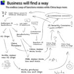
Then, on top of everything else we have the 800 pound gorilla that is China, both in Chip production as well as equipment purchases.
Rising China production is an existential threat to second tier foundries and the 40% of all equipment that continues to flow to China is keeping the equipment industry in the black.
Sooner or later, all the equipment that China has purchased will come on line. Sooner or later China will slow its non China based equipment purchases.
Things are shaky and getting shakier in the overall chip industry. Hardly a confidence inspiring situation as the news flow seems to be more negative when it should be getting more positive on a seasonal basis.
We still love AI and all related things and continue to own Nvidia, but the headwinds in the rest of the semiconductor industry may be building………
About Semiconductor Advisors LLC
Semiconductor Advisors is an RIA (a Registered Investment Advisor),
specializing in technology companies with particular emphasis on semiconductor and semiconductor equipment companies.
We have been covering the space longer and been involved with more transactions than any other financial professional in the space.
We provide research, consulting and advisory services on strategic and financial matters to both industry participants as well as investors.
We offer expert, intelligent, balanced research and advice. Our opinions are very direct and honest and offer an unbiased view as compared to other sources.
Also Read:
AMAT Underwhelms- China & GM & ICAP Headwinds- AI is only Driver- Slow Recovery
LRCX Good but not good enough results, AMAT Epic failure and Slow Steady Recovery
The China Syndrome- The Meltdown Starts- Trump Trounces Taiwan- Chips Clipped