

Earlier this month, TechInsights did a teardown of the Kirin 9030 chip found in Huawei’s Mate 80 Pro Max [1]. Two clear statements were made on the findings: (1) the transistor density of SMIC’s “N+3” process was definitely below that of the earlier 5nm processes from Samsung and TSMC, and (2) metal pitch was aggressively scaled using DUV multi-patterning. Given that the density (formula defined in [2]) is less than 125 MTr/mm2 (Samsung 5LPE), corresponding to a track pitch of 36 nm and gate pitch of 54 nm [3], we can infer that it is the minimum metal pitch that was aggressively scaled, going beyond double patterning. In this article, we will go over the possible paths ahead for SMIC that could ultimately enable transistor densities >300 MTr/mm2, knowing that minimum metal pitch is now likely being patterned by some form of self-aligned quadruple patterning (SAQP).
Some Guiding Numbers for Pitch Scaling
The actual pitches for SMIC’s latest N+3 and previous N+2 processes were found by TechInsights but never revealed publicly. When those processes are discussed in this article, representative pitches will be used.
Thanks for reading Multiple Patterns! Subscribe for free to receive new posts and support my work.
It will be assumed that getting to >300 MTr/mm2 will follow the path shown in Table 1. At N+3, the M0 layer was shrunk aggressively; this will be repeated for M2 at N+4.
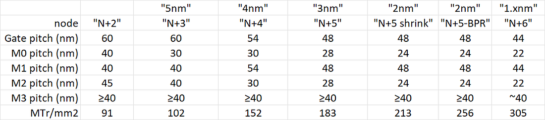 |
Table 1. Possible pitch shrink path from N+2 to >300 MTr/mm2. See text for explanations.
A number of clarifications are needed to explain the numbers used in Table 1.
The transistor density is calculated from the gate pitch and the track pitch, which is taken to be M2 here. We know that for N+3, the track metal is not the minimum pitch metal. The formula is the same as used in [2], with 60% weight on 4-transistor NAND cells covering 3 gate pitches, and 40% weight on a 32-transistor flip-flop covering 19 gate pitches. This gives [6*4/3+0.4*32/19]/(gate pitch*cell height)=1.474/(gate pitch*cell height) as the transistor density formula.
At the “2nm” node, the transition to buried power rail is expected, which enables the cell height to go from 6 tracks to 5 tracks.
For older nodes, M1 pitch can be less that gate pitch, e.g., 2/3 gate pitch, but 36 nm pitch with EUV has stochastic defect density concerns [4,5], so it has been expected that M1 pitch will be relaxed to the same as gate pitch.
A 44 nm gate pitch and 22 nm pitch with buried power rails allowing 5-track cells would be necessary to get over 300 MTr/mm2.
Different SAQP Approaches Proposed
Achieving a minimum metal pitch as small as 30 nm or smaller is no trivial feat. Two methods have been proposed by Huawei and SiCarrier.
Double SALELE
Huawei’s patent CN117751427 discloses what is essentially the SALELE [6] approach applied twice. “SALELE” stands for “self-aligned litho-etch-litho-etch;” it is a more sophisticated version of the traditional litho-etch-litho-etch double patterning approach. Double SALELE means doing SALELE twice to get the quadruple patterning effect (Figure 1).
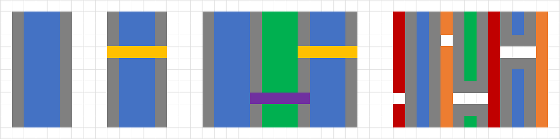 |
Figure 1. Double SALELE approach. Left: First litho-etch (blue), followed by spacer (gray), then etch block/cut (yellow). Center: Second litho-etch (green), followed by etch block/cut (purple). This completes the first SALELE. Right: Second SALELE completed.
In the SALELE approach, sidewall spacers are applied to a first set of lines, formed conventionally, by “litho-etch.” Then these lines may be cut using etch blocks patterned by a second mask. A third mask is used to pattern the second set of lines, with alignment assisted by the sidewall spacers. Then, this second let of lines is cut, using a fourth mask.
This approach consumes an excessive number of masks. Four masks are needed for four sets of lines, so that each line printed by a given mask is separated by sufficient distance (≥ minimum allowed pitch). Four additional masks are needed for the etch block/cut locations, corresponding to each of the four sets of lines. This gives a total of eight masks! Fortunately, this is not the only approach.
Double SADP
SiCarrier’s patent CN117080054 [7] discloses an SAQP-class approach that uses half the number of masks used for double SALELE. In a way, it is a kind of cascaded, double self-aligned double patterning (SADP) (Figure 2).
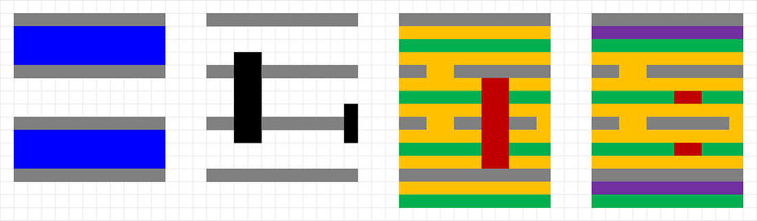 |
Figure 2. Double SADP approach. Left: First spacers (gray) are formed on sidewall of mandrel pattern (blue). Center left: Etch block/cut (black) is applied to the spacer pattern. This completes the first SADP. Center right: Second spacers (yellow) are formed on the sidewalls of the first spacer pattern, followed by a gap fill (green). Etch block/cut (red) is applied to the gap fill pattern. This completes the second SADP. Right: Wide features are formed with a separate (fourth) mask.
The first SADP leaves a set of first spacers which correspond to the first set of metal lines. The gaps left after the second follow-on SADP correspond to the second set of metal lines. Wide metal lines are completed at the end. Like in SALELE, the two sets of lines are cut separately. However, SADP enables twice the line density compared to a single litho-etch, and the cuts can also be made two lines at a time. Thus, the number of masks is halved from 8 to 4.
Diagonal FSAV Grid Becomes a Must
With metal pitches of 30 nm or less, metal linewidths become 15 nm or less. It is actually difficult to focus, even with High-NA EUV, down to a spot as small as this; the Rayleigh resolution limit would be 0.61 wavelength/NA = 0.61*13.5/0.55 = 15 nm. But looking ahead to the sub-2nm node, stochastics will become the overwhelming reason why even with High-NA EUV, directly printing a via is not feasible (Figure 3).
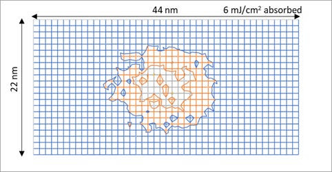 |
Figure 3. Absorbed photon density (1 nm pixel) for a 22 nm x 11 nm via on 44 nm x 22 nm pitch, with 6 mJ/cm2 absorbed EUV dose.
Lithographic difficulty has been a key driving reason for using diagonal via grids [8]. The minimum via pitch at advanced nodes cannot be as small as the minimum metal line pitch (Figure 4). Routing doesn’t require it anyway [8,9].
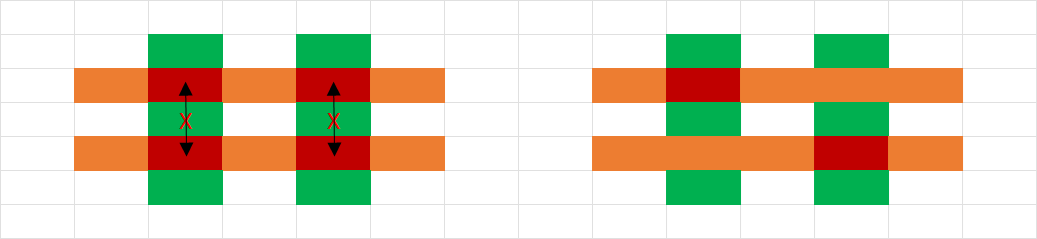 |
Figure 4. Left: The minimum via pitch cannot be as small as the minimum metal line pitch. Right: Diagonal via locations could be allowed.
It will become necessary to fill the intersection area between vertically adjacent metal layers, using the fully self-aligned via process [10]. A focused EUV spot will be wider than the metal linewidth at 3nm and below.
Based on the pitches in Table 1, we can predict the maximum number of masks used for patterning the V0, V1, and V2 layers. With ArF immersion, we allow 80 nm distance between vias [11]. Brute force via multipatterning will result in up to four masks used (Figure 5). A more efficient approach that fits the diagonal via grid is to use LELE double patterning to print portions of diagonal lines that cover the targeted via locations; a third mask would be used if needed to trim the portions if necessary.
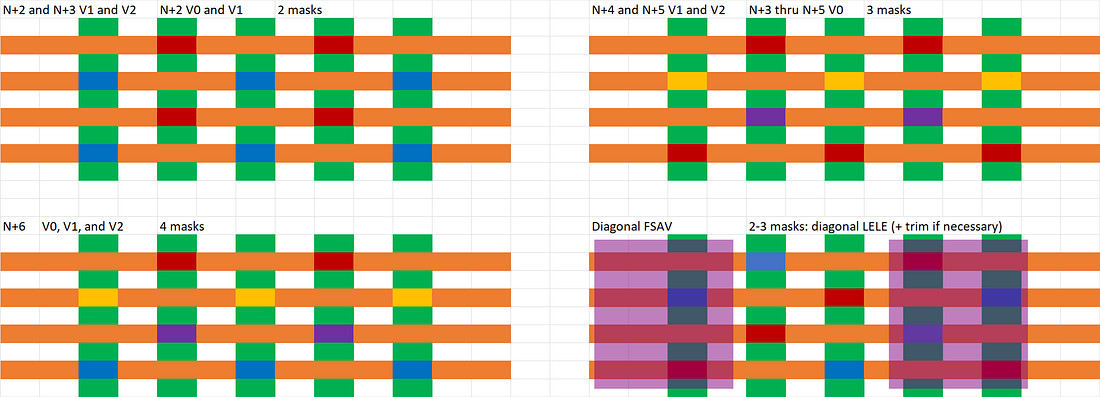 |
Figure 5. Via multipatterning options. Each color represents a different mask. Top left: double patterning is sufficient for N+2, and some via layers of N+3. Top right: triple patterning would become necessary for N+4 and N+5. Bottom left: for N+6, quadruple patterning would become a necessary allowance if still using brute force multipatterning. Bottom right: Diagonal LELE (plus trim mask if necessary) is most efficient for accommodating the diagonal via grid.
Counting Cuts
Besides vias, metal line cuts add significantly to the mask count. For the M0 and M2 layers, the double SADP approach only requires two cut masks, while the double SALELE approach depends on the node pitches. The distances between cuts follow the same rules as for the vias. It could go up to four masks for the 1.x nm node (Figure 6).
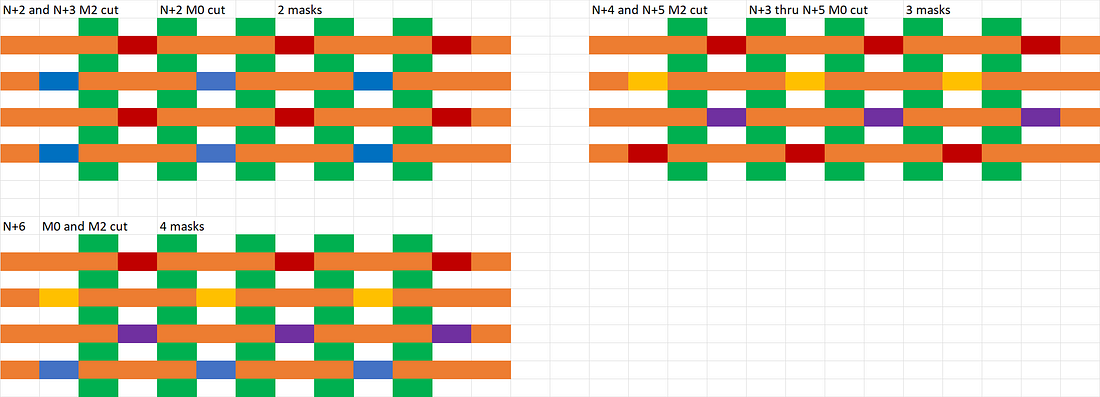 |
Figure 6. Cut mask count for double SALELE metal layers. Each color represents a different mask.
The M1 and M3 layers are likely patterned by SALELE, so that narrow straight line cuts may be used to cut alternate lines, skipping lines in between. This would mean up to four masks (Figure 7).
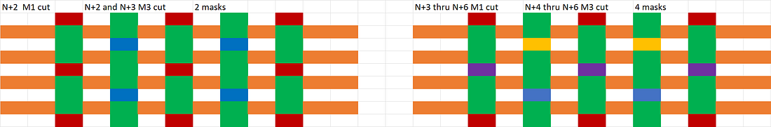 |
Figure 7. Cut mask count for the SALELE metal layers (M1 and M3). Each color represents a different mask.
For EUV, SALELE cuts would still require two masks. Thus, DUV quadruple patterning for this purpose is still cheaper than EUV double patterning [12].
Smooth Ride Forward?
When the mask count increases for the M0 through M3 layers are tallied up for the different possible approaches, we get the overall result in Figure 8.
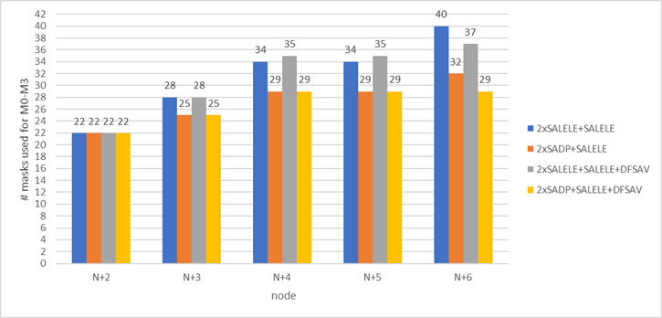 |
Figure 8. Number of masks required for the M0 through M3 layers for the representative nodes N+2 through N+6, for the different possible multipatterning combinations. “2xSALELE” = double SALELE, “2xSADP” = double SADP, “DFSAV” = diagonal line LELE on FSAV, with trim mask. SALELE is assumed applied to the M1 and M3 layers.
The double SALELE approaches will consistently require more masks than the double SADP approaches. The use of diagonal line double patterning with trim mask on FSAV saves three masks for N+6 (44 nm pitch M1, 22 nm pitch M0 and M2). In the best case, only 7 masks have been incrementally added from N+2 to N+4, and the total remained unchanged until N+6. This is to be compared with the worst case, where the mask count increase from N+2 continued after N+5, leading up to 18 masks for N+6.
N+5 is seen to be a convenient shrink of N+4, with no added masks.
Thus, the multipatterning path must be carefully planned several nodes ahead in advance in order to ensure that mask count increase can be manageable.
References
[1] R. Krishnamurthy, “SMIC Steps Toward 5nm: Kirin 9030 Analysis Shows the Foundry’s N+3 Progress,” TechInsights.
[2] Skyjuice, “The Truth of TSMC 5nm,” Angstronomics.
[3] D. Schor, “Samsung 5 nm and 4 nm Update,” Wikichip Fuse.
[4] Y. Li, Q. Wu, Y. Zhao, “A Simulation Study for Typical Design Rule Patterns and Stochastic Printing Failures in a 5 nm Logic Process with EUV Lithography,” CSTIC 2020.
[5] Y-P. Tsai, C-M. Chang, Y-H. Chang, A. Oak, D. Trivkovic, R-H. Kim, “Study of EUV stochastic defect on wafer yield,” Proc. SPIE 12954, 1295404 (2024).
[6] Y. Drissi, W. Gillijns, J. U. Lee, R. R-H. Kim, A. Hamed-Fatehy, R. Kotb, R. N. Sejpal, F. Germain, J. Word, “SALELE Process from Theory to Fabrication,” Proc. SPIE 10962, 109620V (2019).
[7] F. Chen, “SiCarrier’s SAQP-Class Patterning Technique: a Potential Domestic Solution for China’s 5nm and Beyond,” Multiple Patterns.
[8] S-W. Peng, C-M. Hsiao, C-H. Chang, J-T. Tzeng, US Patent Application 20230387002; Y-C. Xiao, W. M. Chan, K-H. Hsieh, US Patent 9530727.
[9] F. Chen, “Exploring Grid-Assisted Multipatterning Scenarios for 10A-14A Nodes,” Multiple Patterns.
[10] J-H. Franke, M. Gallagher, G. Murdoch, S. Halder, A. Juncker, W. Clark, “EPE analysis of sub-N10 BEoL flow with and without fully self-aligned via using Coventor SEMulator3D,” Proc. SPIE 10145, 1014529 (2017).
[11] M. Burkhardt, Y. Xu, H. Tsai, A. Tritchkov, J. Mellmann, “Ultimate 2D Resolution Printing with Negative Tone Development,” Proc. SPIE 9780. 97800E (2016).
Thanks for reading Multiple Patterns! Subscribe for free to receive new posts and support my work. Pledge your support
This article first appeared on Multiple Patterns: Kirin 9030 Hints at SMIC’s Possible Paths Toward >300 MTr/mm2 Without EUV.
Also Read:
Cost, Cycle Time, and Carbon aware TCAD Development of new Technologies
VLSI Technology Symposium – Intel describes i3 process, how does it measure up?
Self-Aligned Spacer Patterning for Minimum Pitch Metal in DRAM


Comments
There are no comments yet.
You must register or log in to view/post comments.