In Their Own Words: TSMC and Open Innovation Platform

In Their Own Words: TSMC and Open Innovation Platform
by Daniel Nenni on 06-01-2019 at 8:00 am

TSMC, the largest and most influential pure-play foundry, has many fascinating stories to tell. In this section, TSMC covers some of their basic history, and explains how creating an ecosystem of partners has been key to their success, and to the growth of the semiconductor industry.

The history of TSMC and its Open Innovation Platform (OIP)® is, like almost everything in semiconductors, driven by the economics of semiconductor manufacturing. Of course, ICs started 50 years ago at Fairchild (very close to where Google is headquartered today, these things go in circles). The planarization approach, whereby a wafer (just 1” originally) went through each process step as a whole, led to mass production. Other companies such as Intel, National, Texas Instruments and AMD soon followed and started the era of the Integrated Device Manufacturer (although we didn’t call them that back then, we just called them semiconductor companies).

The next step was the invention of ASICs with LSI Logic and VLSI Technology as the pioneers. This was the first step of separating design from manufacturing. Although the physical design was still done by the semiconductor company, the concept was executed by the system company. Perhaps the most important aspect of this change was not that part of the design was done at the system company, but rather the idea for the design and the responsibility for using it to build a successful business rested with the system company, whereas IDMs still had the “if we build it they will come” approach, with a catalog of standard parts.

In 1987, TSMC was founded and the separation between manufacture and design was complete. One missing piece of the puzzle was good physical design tools and Cadence was created in 1988 from the merger of SDA and ECAD (and soon after, Tangent). Cadence was the only supplier of design tools for physical place and route at the time. It was now possible for a system company to buy design tools, design their own chip and have TSMC manufacture it. The system company was completely responsible for the concept, the design, and selling the end-product (either the chip itself or a system containing it). TSMC was completely responsible for the manufacturing (usually including test, packaging and logistics too).

At the time, the interface between the foundry and the design group was fairly simple. The foundry would produce design rules and SPICE parameters for the designers; the design would be given back to the foundry as a GDSII file and a test program. Basic standard cells were required, and these were available on the open market from companies like Artisan, or some groups would design their own. Eventually TSMC would supply standard cells, either designed in-house or from Artisan or other library vendors (bearing an underlining royalty model transparent to end users). However, as manufacturing complexity grew, the gap between manufacturing and design grew too. This caused a big problem for TSMC: there was a lag from when TSMC wanted to get designs into high volume manufacturing and when the design groups were ready to tape out. Since a huge part of the cost of a fab is depreciation on the building and the equipment, which is largely fixed, this was a problem that needed to be addressed.

At 65 nm TSMC started the Open Innovation Platform (OIP) program. It began at a relatively small scale but from 65 nm to 40 nm to 28 nm the amount of manpower involved went up by a factor of 7. By 16 nm FinFET, half of the design effort is IP qualification and physical design because IP is used so extensively in modern SoCs, OIP actively collaborated with EDA and IP vendors early in the life-cycle of each

process to ensure that design flows and critical IP were ready early. In this way, designs would tape-out just in time as the fab was starting to ramp, so that the demand for wafers was well-matched with the supply.

In some ways the industry has gone a full circle, with the foundry and the design ecosystem together operating as a virtual IDM. The existence of TSMC’s OIP program further sped up disaggregation of the semiconductor supply chain. Partly, this was enabled by the existence of a healthy EDA industry and an increasingly healthy IP industry. As chip designs had grown more complex and entered the SoC era, the amount of IP on each chip was beyond the capability or the desire of each design group to create. But, especially in a new process, EDA and IP qualification was a problem.

On the EDA side, each new process came with some new discontinuous requirements that required more than just expanding the capacity and speed of the tools to keep up with increasing design size. Strained silicon, high-K metal gate, double patterning and FinFETs each require new support in the tools and designs to drive the development and test of the innovative technology.

On the IP side, design groups increasingly wanted to focus all their efforts on parts of their chip that differentiated them from their competition, and not on re-designing standard interfaces. But that meant that IP companies needed to create the standard interfaces and have them validated in silicon much earlier than before.

The result of OIP has been to create an ecosystem of EDA and IP companies, along with TSMC’s manufacturing, to speed up innovation everywhere. Because EDA and IP groups need to start work before everything about the process is ready and stable, the OIP ecosystem requires a high level of cooperation and trust.

When TSMC was founded in 1987, it really created two industries. The first, obviously, is the foundry industry that TSMC pioneered before others entered. The second was the fabless semiconductor companies that do not need to invest in fabs. This has been so successful that two of the top 10 semiconductor companies, Qualcomm and Broadcom, are fabless and all the top FPGA companies are fabless.

The foundry/fabless model largely replaced IDMs and ASIC. An ecosystem of co-operating specialist companies innovates fast. The old model of having process, design tools and IP all integrated under one roof has largely disappeared, along with the “not invented here” syndrome that slowed progress since ideas from outside the IDMs had a tough time penetrating. Even some of the earliest IDMs from the “Real men have fabs” era have gone “fab lite” and use foundries for some of their capacity, typically at the most advanced nodes.

Legendary TSMC Chairman Morris Chang’s “Grand Alliance” is a business model innovation of which OIP is an important part, gathering all the significant players together to support customers—not just EDA and IP, but also equipment and materials suppliers, especially for high-end lithography.

Digging down another level into OIP, there are several important components that allow TSMC to coordinate the design ecosystem for their customers.

  • EDA: the commercial design tool business flourished when designs got too large for hand-crafted approaches and most semiconductor companies realized they did not have the expertise or resources in-house to develop all their own tools. This was driven more strongly in the front-end with the invention of ASIC, especially gate-arrays; and then in the back end with the invention of
  • IP: this used to be a niche business with a mixed reputation, but now is very important with companies like ARM, Imagination, CEVA, Cadence, and Synopsys, all carrying portfolios of important IP such as microprocessors, DDRx, Ethernet, flash memory and so on. In fact, large SoCs now contain over 50% and sometimes as much as 80% TSMC has well over 5,500 qualified IP blocks for customers.
  • Services: design services and other value-chain services calibrated with TSMC process technology helps customers maximize efficiency and profit, getting designs into high volume production rapidly
  • Investment: TSMC and its customers invest over $12 billion a year. TSMC and its OIP partners alone invest over $1.5 billion. On advanced lithography, TSMC has further invested $1.3 billion in

Processes are continuing to get more advanced and complex, and the size of a fab that is economical also continues to increase. This means that collaboration needs to increase as the only way to both keep costs in check and ensure that all the pieces required for a successful design are ready just when they are needed.

TSMC has been building an increasingly rich ecosystem for over 25 years and feedback from partners is that they see benefits sooner and more consistently than when dealing with other foundries. Success comes from integrating usage, business models, technology and the OIP ecosystem so that everyone succeeds. There are a lot of moving parts that all have to be ready. It is not possible to design a modern SoC without design tools, more and more SoCs involve more and more 3rd party IP, and, at the heart of it all, the process and the manufacturing ramp with its associated yield learning all needs to be in place at TSMC.

The proof is in the numbers. Fabless growth in 2013 is forecasted to be 9%, over twice the increase in the overall industry at 4%. Fabless has doubled in size as a percentage of the semiconductor market from 8% to 16% during a period when the growth in the overall semiconductor market has been unimpressive. TSMC’s contribution to semiconductor revenue grew from 10% to 17% over the same period.

The OIP ecosystem has been a key pillar in enabling this sea change in the semiconductor industry.

TSMC 2019 Update

2019 TSMC Technology Symposium Review Part I

TSMC Technology Symposium Review Part II


Global Unichip Corporation

Another facet of TSMC is GUC, Global Unichip Corporation. It is a partially owned subsidiary and also an important partner, providing design services and allowing TSMC themselves to continue to be a pure-play foundry. GUC was founded in 1998 with 10 employees as what has come to be known as a “Design Service” company. It ramped fast and by 2000 it employed over 100 people.

The years between 2003 and 2010 were milestone years for GUC, representing a period of unprecedented growth. The era was marked by a strengthening of both business and technology relationships with the largest semiconductor foundry in the world, TSMC. That relationship set GUC on firm growth, bringing over the core of today’s management and the business strategy that guides the company today.

In 2003, TSMC assumed an ownership stake in GUC. But the foundry leader’s investment went far beyond financial investment. Part of its strategy to enhance the return on its investment was to move GUC to a global business strategy and put it on the road to being an advanced technology leader.

The technology model, and the business model that accompanied it, soon began to gain traction. Prior to 2003, much of GUC’s business came from the consumer electronics companies who tended to utilize more mature technologies and were primarily located in Taiwan. With the installation of new management, and new business and technology models, business emphasis began to migrate to the more technically sophisticated networking and communications sectors that required more advanced technologies. In 2004, 100% of GUC’s revenue was at  the 0.13 µm technology node; by 2005, 5% of revenue came from the new 90 nm node and a year later, an additional 3% of revenue came from the emerging 65 nm node.

The impact of this trend was soon seen in the company finances. Revenue jumped from $20 million in 2002 to $27 million in 2003, $32 million in 2004, and a whopping $48 million in 2005—more than doubling the revenue over a four year period.

The year 2006 marked another major milestone. In the third quarter of that year, GUC became a publicly traded company when it offered its shares on the Taiwan Stock Exchange.

The operations side instituted a major focus on advanced technology. In 2007, the company developed an advanced technology digital design flow, followed shortly thereafter by a low power design flow. As a result, the company saw a large increase in the size of their designs, many with gate counts jumping exponentially. In the face of an industry-wide recession in 2009, GUC showed its confidence in the future by investing heavily in internal IP development, in particular, IP targeting the networking market segment.

This era of prosperity was reflected by a broad set of indices. Annual revenue in 2006 more than doubled that of 2005 ($48 million) at $103 million, then more than doubled again in 2007 to $216 million. In 2008, revenue jumped to $295 million before falling during the recession of 2009 to $252 million. In 2008, GUC saw a jump in revenue from advanced technology to 21 % and to 34 % in 2009, with 1 % of that coming from leading edge 40 nm products. Like all technology companies, GUC experienced a financial decline in 2009, with revenues dropping to $252 million.

But the company would rebound quickly in 2010, posting revenues of $327 million with advanced technologies accounting for 42% of that total. The year also proved auspicious. Driven by the recession to examine its business model, GUC would begin making a series of strategic decisions that would allow it to capitalize on a new era of semiconductor device design.

The company’s growth as an innovative force in the semiconductor industry is also reflected in the number of new employees required to implement increasingly complex technologies. At the end of 2003, GUC employed 132 people, most of them in Taiwan. Three years later, that number had more than doubled to 287 and by the start of 2010, the company counted 484 employees, a number that has held relatively steady through 2013. Employee growth was fueled by expanded geographic growth. GUC opened its first international office when it established a subsidiary in North America (GUC N.A.) in February of 2004 and then opened its Japan office in June of 2005. Nearly three years later, in May of 2008, the company opened its third international office, GUC Europe, in Amsterdam, The Netherlands and one month later opened an office in Korea. GUC entered the fast-growing China market when it opened an office in one of that country’s technology hubs near Shanghai in 2009.

Success in the semiconductor industry going forward is going to be heavily weighted by the ability to leverage industry’s third-party infrastructure that has now matured. Foundries are at the leading edge of the infrastructure, providing the most advanced process technologies, as well as specialized technologies to all comers. IP and chip design implementation are also being outsourced, cost-effectively utilizing technology and financial resources.

It is in this new and exciting environment that GUC evolved the Flexible ASIC Model, which is designed to provide the most effective, efficient and flexible path to semiconductor innovation.

The Flexible ASIC Model is a response to both the business and technical challenges facing today’s semiconductor companies. This model allows companies to allocate their resources more efficiently. It brings together design expertise, systems knowledge and manufacturing resources to efficiently drive delivery of the final packaged IC. The model’s basic strategy is to spread design risks and to minimize IDM, fabless and OEM (Original Equipment Manufacturers) upfront semiconductor-related fiscal and human capital investments. The goal is to increase the efficiency of the entire value chain, from concept to delivery; to shorten all phases of the development cycle; and to ultimately increase device yield quality and reliability.

At the heart of the Flexible ASIC Model is integrated manufacturing. GUC has made a strategic choice to work exclusively with TSMC, the semiconductor industry’s leading foundry service company. It is this relationship that plays an integral role in the company’s ability to achieve early advanced technology access and match designs to manufacturing resources.

Spotlight: Dr. Morris Chang

Dell changed the way personal computers are manufactured and sold. Starbucks changed the amount we would pay for a cup of coffee. eBay took the yard sale out of our yards. TSMC took the semiconductor manufacturing costs off our balance sheets and out of our capital investments.

It’s hard to overstate the impact that Dr. Morris Chang, Founder, Chairman, and until-recently CEO of TSMC, has had on the industry. He has been influential as a leader in business model innovation, and has earned his company roughly 50% of the foundry market share.

Chang left his native China in 1949, moving to the US to attend Harvard University. He soon transferred to MIT as he followed his interest in technology. After earning his MS in 1953 from MIT’s mechanical engineering graduate school, Morris went directly into the semiconductor industry at the process level with Sylvania Semiconductor and was quickly moved to management.

Chang moved to Texas Instruments in 1958, where he stayed for 25 years, rising to VP of the worldwide semiconductor business (and also earned a PhD in electrical engineering from Stanford in 1964). At TI, he worked on a four transistor project in which the manufacturing was done by IBM, thus engaging in one of the early semiconductor-foundry relationships. Also at TI, Chang developed a new model of semiconductor pricing that sacrificed early profits to gain market share and to achieve manufacturing yields that would lead to higher long-term profits.

Chang left TI in 1983 and did a short stint at General Instrument Corporation. He then moved to Taiwan to head the Industrial Technology Research Institute (ITRI), which led to the founding of TSMC.

Chang noticed in the early 1980s, while at TI and GI, that top engineers were leaving and forming their own semiconductor companies. Unfortunately, the heavy capital requirement of semiconductor manufacturing was a gating factor. The cost back then was $5-10 million to start a semiconductor company without manufacturing and $50-100 million to start a semiconductor company with manufacturing. Some of these start-ups used excess capacity from IDMs but were subjected to uncertainties in foundry capacity and sometimes had to buy wafers from a competitor. Around this time, 1985, the first truly fabless startups, like Xilinx and Chips and Technologies, were launched and doing well.

It was in 1987, within this nascent fabless environment, that Chang started TSMC. Although TSMC started two process nodes behind where semiconductor manufacturers (IDMs) were at the time, they had the advantage of being a pure-play foundry, not a competitor. Their focus was on their customers.

Morris Chang made the first TSMC sales calls with a single brochure: TSMC Core Values: Integrity, Commitment, Innovation, Partnership. Four or five years later, TSMC was only behind by one process node and the orders started pouring in. In 10 years, TSMC caught up with IDMs (except for Intel) and the fabless semiconductor industry blossomed, enabling a whole new era of semiconductor design and manufacturing. In the last 20 years, and still today, even the remaining IDMs are being forced to go fabless or fab-lite at 28 nm and below due to high costs and daunting technical challenges.

Dr. Morris Chang in 2007.

Dr. Morris Chang turned 82 on July 10th, 2013. He is still running TSMC full time as the founding Chairman. He works from 8:30 am to 6:30 pm like most TSMC employees and says that a successful company life cycle is: rapid expansion, a period of consolidation, and maturity. The same could be said about Chang himself.

2019 Update: Dr. Morris Chang

In 2017 the TSMC Museum of Innovation opened Under Fab 12 in Hsinchu Taiwan. It not only commemorates the history of semiconductors and TSMC but also the life of Dr. Morris Chang. Morris Chang’s wife Sophie was actively involved in this project:

The TSMC Museum of Innovation encompasses three exhibition galleries: “A World of Innovation,” “Unleashing Innovation,” and “Dr. Morris Chang, TSMC Founder.” Through interactive technology, digital content, and historical documents we will learn about the pervasiveness of ICs in our daily lives and about their continued advancement. In addition, we will learn how ICs are making our lives more fulfilling and how they are driving technology beyond our imagination. We will also learn how TSMC contributes to global IC innovation and to Taiwan’s economy.

In 2018 Dr. Morris Chang retired from TSMC for the second and final time:

TSMC Dr. Morris Chang Announces Retirement in June 2018. Future Dual Leadership Will Be Mark Liu as Chairman And C.C. Wei as CEO.

Issued by: TSMC Issued on: 2017/10/02

Hsinchu, Taiwan, R.O.C. – Oct. 2, 2017 – TSMC Chairman Morris Chang today announces: “I will retire from the Company immediately after the Annual Shareholders Meeting in early June, 2018. I will not be a director in the next term of the board of directors. Nor will I participate in any TSMC management activities after the Annual Shareholders Meeting in early June, 2018. From early June, 2018 on, TSMC will be under the dual leadership of Dr. Mark Liu and Dr. C.C. Wei. Dr. Mark Liu will be the Chairman of the Board, and Dr. C.C. Wei will be the Chief Executive Officer. All present directors of the board have agreed to be nominated, and if elected, serve as directors of the board during the next term. They have also agreed to support the aforementioned dual leadership of the Company under Drs. Liu and Wei. Chairman Morris Chang further said, “The past 30-odd years, during which I founded and devoted myself to TSMC, have been an extraordinarily exciting and happy phase of my life. Now, I want to reserve my remaining years for myself and my family. Mark and CC have been Co-CEO’s of the Company since 2013 and have performed outstandingly. After my retirement, with the continued supervision and support of an essentially unchanged board, and under the dual leadership of Mark and CC, I am confident that TSMC will continue to perform exceptionally.”


400G Ethernet test chip tapes-out at 7nm from eSilicon

400G Ethernet test chip tapes-out at 7nm from eSilicon
by Tom Simon on 05-24-2019 at 10:00 am

Since the beginning of May eSilicon has announced the tape-out of three TSMC 7nm test chips. The first of these, a 7nm 400G Ethernet Gearbox/Retimer design, caught my eye and I followed up with Hugh Durdan, their vice president of strategy and products, to learn more about it. Rather than just respin their 56G SerDes, they decided to add the 112G SerDes, and at the same time use this vehicle for several other objectives. The gearbox in this chip contains 8 lanes of 56G and 4 lanes at 112G, allowing it to handle 400G Ethernet traffic. More than just showing that the SerDes work at 7nm, the configuration allows them to demonstrate a number of other things as well.

In our call, Hugh mentioned that they chose to work with Precise-ITC who develops IP for Ethernet and Optical Transport Network (OTN). They saw this as an opportunity to combine eSilicon interface IP with 3rd party IP to go through the process of integration and ensure that their StarDesigner 7nm flow was working as they expected. In essence this is a pipe cleaner of their SOC flow for 7nm.

Precise-ITC contributed a Forward Error Correction (FEC) block, Media Access Controller (MAC) and the Gearbox block. Having higher level functionality offers increased confidence in each element of the test chip. Hugh pointed out that this is a chip that customers can actually use as they evaluate the eSilicon’s offering. The chip will feature long reach and use only around 5W for the entire gearbox.

Designing at 7nm is even more difficult than at previous nodes. Lithography requirement impose many new restrictions on the layout. This makes designing chips with analog content challenging. Another aspect of the design that plays a critical role in the success of a chip like this is the packaging. Hugh told me that they used this opportunity to anticipate the complexity of designs with a much higher lane count by adding a more complex package design for some of the lanes. They also have the ability to inject noise during testing to ensure that the SerDes will perform in larger and more complex environments.

eSilicon is expecting to get silicon back in their lab by Q3 in 2019. They will make a test board that customers can use to put the SerDes and Ethernet related IP through its paces. The 112G SerDes will open the doors to continued development of Terabit Ethernet, which is becoming necessary with the explosion of data center throughput requirements.

eSilicon has consistently expended resources to stay at the leading edge of SOC technology. Their other May test chips included HBM and AI/ML designs all at 7nm. At the same time their partnerships will make life easier for their customers who are going to want to add advanced functionality to their designs. Test chips like this are a win for eSilicon, TSMC, Precise-ITC and their customers. We can eagerly await the return of silicon from this and their other test chips to learn more about how 7nm will perform in the wild. For more details, refer to the announcement on their website.


An evolution in FPGAs

An evolution in FPGAs
by Tom Simon on 05-24-2019 at 5:00 am

Why does it seem like current FPGA devices work very much like the original telephone systems with exchanges where workers connected calls using cords and plugs? Achronix thinks it is now time to jettison Switch Blocks and adopt a new approach. Their motivation is to improve the suitability of FPGAs to machine learning applications, which means giving them more ASIC-like performance characteristics. There is, however, more to this than just updating how data is moved around on the chip.

Achronix has identified three aspect of FPGAs that need to be improved to make them the preferred choice for implementing machine learning applications. Naturally, they will need to retain their hallmark flexibility and adaptability. The three architecture requirements for efficient data acceleration are compute performance, data movement and memory hierarchy. Achronix took a step back and looked at each element in order to recreate how programmable logic should work in the age of machine learning. Their new Speedster 7t is the result. Their goal was to break the historical bottlenecks that have reduced FPGA efficiency. They call the result FPGA+.

Built on TSMC’s 7nm node these new chips have several important innovations. Just as all our phone calls are now routed with packet technology, Achronix’s Speedster 7t will use a 2 dimensional arrayed network on chip (NoC) to move data between the compute elements, memories and interfaces. The NoC is made up of a grid of master and slave Network Access Points (NAPs). Each row/column operates at 256b @2.0Gbps, a combined 512 Gbps. This puts device level bandwidth in the range of 20Tbps.

The NoC supports specific connection modes for transactions (AXI), Ethernet packets, unpacketed data streams and NAP to NAP for FPGA internal connections. One benefit of this is that the NoC can be used to preload data into memory from PCIe without involving the processing core. Another advantage is that the network structure removes pressure during placement to position connected logic units near each other, which was a major source of congestion and floor planning headaches.

The NoC also allows the Achronix Speedster 7t to support 400G operation. Instead of having to run a 1000 bit bus at 724 MHz, the Speedster 7t can support 4 parallel 256 bit buses running at 506MHz to easily handle the throughput. This is especially useful when deep header inspection is required.

For peripheral interfaces, the approach that Achronix uses is to offer a highly scalable SerDes that can run from 1 to 112Gbps to support PCIe and Ethernet. They can include up to 72 of these per device. For Ethernet, they can run 4x 100Gbps or 8x 50Gbps. Lower rate Ethernet connections are also supported for back compatibility. They support PCIe Gen5, with up to 512 Gbps per port, with two ports per device.

The real advantage of their architecture becomes apparent when we look at the compute architecture. Rather than have separate DSPs LUTs and block memories, they have combined these into Machine Learning Processors (MLPs). This immediately frees up bandwidth on the FPGA routing. These three elements are used heavily together in machine learning applications, so combining them is a big advantage for their architecture.

AI and ML algorithms are all over the map on the need for mathematical precision. Sometimes large float precision is used, in other cases there has been a move to low precision integer. Google even has their own Bfloat precision. To handle this wide variety, Achronix has developed fracturable float and integer MACs. The support for multiple number formats provides high utilization of MAC resources. The MLPs also include 72Kbit RAM blocks, and memory and operand cascade capabilities.

For AI and ML applications, local memory is important, but so is system RAM. Achronix decided to use GDDR6 on their Speedster 7t family. It offers lower cost, easier and more flexible system design and extremely high bandwidth. Of course DDR4 can be used for less demanding storage needs as well. The use of GDDR6 allows each design to tune their memory needs, rather than being dependent on memory that is configured in the same package as the programmable device. Speedster 7t supports up to 8 devices with throughput of 4 Tbps.

There is a lot to digest in this announcement, it is worth looking over the whole thing. Looking back, this evolution will seem as obvious as how our old wired table top phones evolved into highly connected and integrated communications devices. The take-away is that this level of innovation will lead to unforeseen advances in end product capabilities. According to the Achronix Speedster 7t announcement, their design tools are ready now and they will have a development board ready in Q4.


Learning on the Edge Investment Thesis

Learning on the Edge Investment Thesis
by Jim Hogan on 05-20-2019 at 5:00 am

It is said that it will cost as much as $600M to develop a 5nm chip. At that price, only a few companies can afford to play, and with that amount of cash in, innovation is severely limited.

At the same time, there is a stampede in the artificial intelligence (AI) market where around 60 startups have appeared, many of which have already raised $60M or more. $12B was raised for AI startups in 2017 and, according to International Data Corporation (IDC), is expected to grow to $57B by 2021. Most of these are going after the data center, which is necessary to get the required ROI when you have a big raise. The chance of success is slim, and the risks are high. There is an alternative for investors and startups.

In this investment thesis, I talk about large disruptive changes happening in the semiconductor industry and the opportunities this creates for innovative architectures and business models.

I used a specific startup – Xceler, who are taking an alternative route to the development of an AI processor. A second organization – Silicon Catalyst is enabling them to bring silicon to market with much lower cost and risk. In the interest of full disclosure, I am a director and investor of both Xceler and Silicon Catalyst.

I love getting feedback and I share that feedback with people, so please let me know what you think. Thanks – Jim


Fig 1. Costs associated with SoC development at each manufacturing node. Source: IBS

Success with semiconductor investment in general, and AI specifically, is a multi-step process. At each stage, the goal is to reduce risk and maximize the potential for success at the lowest possible cost in dollars and time.

The low-risk structured approach comes down to executing the following steps:

  • The requirements in the chosen markets are distilled into the minimum functionality required, and target architectures identified.
  • The solutions are prototyped using FPGAs and proven in the market, creating initial revenue.

With these two steps, you have proof of technology proficiency and early market validation.

  • The solutions are then retargeted to silicon, adding further architectural innovations. An important element of this step is the utilization of silicon incubators that significantly reduce cost and risk. For an AI semiconductor startup, aside for people costs, significant costs are EDA tools and silicon. Typically, this is in the range of $3 to $5M. If the company can avoid or reduce that expense, they will see a much higher enterprise valuation and retain more ownership for the founders and early investors.

Identify the Market Opportunity


Source: AI Insight, August 30th, 2018

The AI/ML market in the data center is large. For a lot of applications, data collected at various nodes will move back to the data center. These are the public clouds such as those run by large data center companies. The problem for a semiconductor company, or sub-system vendor, is the business model associated with AI/ML in the datacenter. Systems and semiconductor companies build hardware and tools that are powerful and can run a multitude of applications, but the question is what type of AI/ML and what specific applications? It is a solution looking for a market. You need something that people would want to use.

The Cloud provides the infrastructure that your accelerator is integrated into, and they sell repeated services/applications on top of it until the product reaches the end of life. That is not a sustainable business for the technology provider. You can only sell so many units and you can’t keep selling the same volume every year. Consider how NVIDIA’s GP/GPU sales are tapering off. Sales are typically tied to the silicon cycle where every few years more silicon at a lower price, lower power consumption and improved performance becomes available. The services to get customers on board are offered for free, which is the best price, or for cheap, as the service provider is relying on volume sales with a lot of customers/users. This drives the commoditization of the underlying infrastructure as the service providers want the infrastructure at a price that makes business sense for them. In addition, with the slowing of Moore’s law, this forced obsolescence of technology is no longer a driving factor.

The ideal target is a problem looking for a solution, and for Xceler, it was found in the industrial space. Everybody wants to deploy IIoT (Industrial IoT with AI/ML), but each company is looking for the right solution. Consumer IoT was considered but most of the solutions are nice or cool to have, as opposed to must-have. In the consumer space, there are multiple policy hurdles such as legal, privacy, security, or liability. The adoption of these solutions requires a socio-economic behavioral change in the consumer mindset. It is something that requires a generational adoption cycle and a lot of marketing/PR dollars. Conversely, the adoption of industrial solutions is faster because it is a must-have capability that directly affects their bottom line.

Even though the IIoT market is fragmented, fragmentation can be your friend. Each of the larger companies in this space has a top line revenue of $50 billion per year plus. Even with limited market penetration, it is possible to build a sizeable revenue base. There are many potential end-customers, collectively presenting an opportunity, unlike the data center space where there are only a few end customers.

Predictive training and learning on the edge – the dream is now a reality with AI.
Web-based solutions appear to be free. However, someone is paying for the services. In the case of the web, it is advertisers or people trying to sell products. In the industrial space, suppliers are selling both the hardware and the solution. They are directly providing value to the purchaser and can thus make money from that directly, plus there is the potential for future revenue as more capabilities are added.

Every edge-based application is different. This fragmentation is one reason why people are scared of the edge market. You must have the ability to personalize and adapt to the context in which you are deployed. That requires learning on the edge. Inferencing is not enough. If the link breaks, what do you do? Solutions that only perform inferencing could endanger lives.

Some people are trying to build edge-based platforms. These often contain custom edge-based processors for a specific vertical application. They have the characteristics of very high volume but relatively low average selling price in comparison to Cloud devices.

I asked the founder and CEO of Xceler, Gautam Kavipurapu, about his company’s experience in the development of an edge-based processor and application. “We are running a pilot program for a company that makes large gas turbines. They are instrumented in many ways. Fuel valves have flow controls, sensors record vibration and sound, rotation speed at different stages of the turbine is measured, combustion chamber temperature – about 1000 sensors in total. We process the data and do predictive maintenance analysis.”

When the processor is connected to the machine and without connectivity to the Cloud, which may not exist for security reasons, the profile for the normally functioning system is observed. It builds a basic model for the machine, and over time, that model is refined. When you get deviations, the data from the sensors is cross-correlated in real time to figure out what is causing the anomaly. A connection to the Cloud enables the heavy lifting to build a refined model and make micro-refinements to it. However, there are huge advantages in doing the initial processing at the edge in terms of latency and power.

Define the Right Architecture
Systems need to be architected for the problems that they are solving. “We look at problems as hard real-time, near real-time or user time,” explains Kavipurapu. “Hard real-time requires response times of 5 microseconds or less; near real-time requires response times within a few milliseconds, and lastly, user time can take hundreds of milliseconds or minutes. Consumer applications fall within the last category and usually do not have Software License Agreements (SLAs)[BB2] [BB3] and performance commitments so they can work in concert with the Cloud. For problems that require hard or near real-time responses, relying on the Cloud is not viable as the round-trip time itself will take several milliseconds if it manages to complete at all.

“We have seen edge-processors evolve over time. Initially, machine learning on the edge meant collecting data and moving it to the cloud. Both the learning and inferencing were done in the Cloud. The next stage of advancement enabled some inferencing to be done on the edge, but the data and the model remain in the Cloud. Today, we need to move some of the learning to the edge, especially when real-time constraints exist, or you have concerns about security.”

Prototype and Create Revenue Stream
For this class of problem, it is possible to prototype it in an FPGA. For applications that do not need blistering performance, you can even go to market in the seed round with this solution. This offsets the need for more investment dollars and enables the concept to be validated.

“With Xceler, we started with an FPGA solution. They are acceptable in the market place we are targeting since they have good price/performance and power numbers. They are comparable to x86-based systems in price points and provide higher performance. The only downsides are that the margins are compressed, and certain architectural possibilities are not available in an FPGA solution.”

Migrate to Silicon
To capture more value, you do need a solution that is cheaper, faster and lower power. “That involves building a chip, or Edge-Based Processor (EBU),” adds Kavipurapu. “For the control processor, we are using a RISC-V implementation from SiFive. SiFive does the backend design implementation, reducing the risk for us. SiFive is also a Silicon Catalyst partner. We expect our FPGA solution to translate to between 20 million to about 36 million ASIC gates and so the proposed chip does not have to be that large.”

The only risk that remains is silicon risk. By doing the chip in 28nm, a well-understood fabrication process, the manufacturing silicon risk is minimized. All that remains are closing the design and timing which is a much-reduced problem. We have taken out most of the variability in the design element. In addition, we have restrained our design approach using only simple standard cell design with no custom blocks and no esoteric attempts at power reduction.”

Refine architecture
The FPGA solution cannot run faster than about 100MHz. “With an FPGA, we are also constrained by the memory architecture,” explains Kavipurapu. “For the custom chip, we are deploying a superior memory sub-system. New processing techniques require memory for data movement and storage. For us, to execute each computation, it takes about 15 instructions on an FPGA, which will be reduced to 4 or 5 on the ASIC. In terms of clock frequency, we will be running at 500 MHz to 1 GHz in an ASIC at a much-reduced power.”

Usage of silicon incubator
The goal of Silicon Catalyst is to limit the friction for getting an IC startup to the point they can secure an institutional Series A round by reducing the barriers to innovation. This has provided Xceler with a significant advantage compared to potential competition. While the competition struggles with multiple tape outs to achieve working silicon, burning through their dollars before first revenue, Xceler had first revenue even before the tape out. This happened because of the lower risk strategy and help from Silicon Catalyst and others.

“Silicon Catalyst offers through in-kind contributions from ecosystem partners capabilities for startups to get the tools and silicon they need,” says Kavipurapu. “It enables them to get an A round of funding that is nice in terms of valuation and raise. They bring the ability to prototype a chip at a very low cost. We get free shuttles services from TSMC. We do not have to pony up for chip design tools because there are in-kind partnerships for tools from Synopsys. We have licenses to each tool for 2 years. Silicon Catalyst also has a lot of chip industry veterans. I am not a chip guy and neither is my team. When it comes to silicon, Silicon Catalyst adds a lot of value.”

The result is that Xceler will have working samples for a little over $10M. They have customers and could be breakeven before they get to silicon.

Conclusions
We are in an era where innovation is more important than raw speed, the number of transistors or the amount of money invested. There are opportunities everywhere and getting to market with silicon no longer requires building silicon for extremely high volumes and margins. We are in the age of custom solutions designed to solve real problems and there are countless opportunities at the edge.

I’m convinced that Xceler’ s opportunity is much less risky with the help of Silicon Catalyst and the use of an open source architecture (RISC-V). I believe there will be many companies that will follow a similar path – Jim[RC5].

A Final Note
Gautam Kavipurapu was critical to me in creating this post so I’d like to tell you a bit more about him. Gautam has 20 years of experience at both large and small companies in operations, technology and management roles, including setting up and running geographically distributed teams of over 150 employees (India, US, and Europe). Gautam has 14 issued and several pending patents covering systems, networking, computer architecture. He also has several IEEE conference papers to his credit. Gautam’s team at IRIS Holdings in 2001 demonstrated a “Virtual Router,” a software router (modeled as a dataflow machine similar to Google Tensor) on a PC with NIC cards as part of the IRIS (Integrated Routing and Intelligent Switching) system development (Today’s NFV). His inventions and innovations have preceded major technology to various companies in the storage and computing industry worldwide for millions of dollars and cited in more than 350 issued patents. Gautam has an Executive MBA from INSEAD and a BSEE from Georgia Institute of Technology.


Re Energizing Silicon Innovation

Re Energizing Silicon Innovation
by Bernard Murphy on 05-13-2019 at 12:00 pm

Hardware is roaring back into prominence in technology innovation, from advanced cars to robots, smart homes and smart cities, 5G communication and the burgeoning electronification of industry, medicine and utilities. While software continues to play a role, all of these capabilities depend fundamentally on advances in hardware and particularly novel chip solutions: in sensing, high performance and/or low power compute and communication, AI accelerators and many more functions. Yet amidst this explosive growth, the semiconductor industry has massively consolidated. Fewer and bigger companies do their part to drive innovation but are naturally more risk-averse and more inclined to evolutionary rather than revolutionary advances. Where’s all the real innovation and risk-taking going to come from in this environment?

Thirty to forty years ago, if you could make a convincing case there were plenty of VCs ready to bankroll your venture. As manufacturing costs for advanced processes grew, VCs found the comparably minor capital needs of software ventures much more attractive and steered away from silicon business plans. But designers didn’t stop having ideas or feeling the itch to start new enterprises; they were just stalled by a seemingly insurmountable barrier to entry – raising seed and Series A funding.

Everyone knew this, but Rick Lazansky wanted to do something about it. Rick is a serial entrepreneur, actively involved in the investment community. He believed the industry needed an incubator to help silicon innovators with good ideas get past this hurdle. Incubators and accelerators are not new concepts but his creation, Silicon Catalyst, makes particular allowance for the special needs of this domain. They provide a pool of seed investors, two years of design tool access, manufacturing and test, access to a wide range of advisors with lots of industry experience and access to a premium group of strategic partners looking for innovations they need. You’ll still have to raise some of your own investment to prove you have skin in the game, but the barrier is now much less daunting.

Before you quit your job, get a second mortgage on the house and tell your significant other that the family will be living with your parents if your venture doesn’t work out, remember that as with any incubator, you’re going to have to do some work to be accepted; I’ll get to that. But first some more detail on that buffet of goodies to which you’ll have access if you cross that hurdle.

Your immediate concern is probably how you manage EDA, IP and design services, MPW, packaging and test costs. Silicon Catalyst has assembled a group of 25+ in-kind partners who will provide 2 years of free or significantly-discounted access to their capabilities and services from the time your clock starts. These include Synopsys for design tools, S2C for emulation, SiFive and Silvaco for IP, TSMC MPWs for prototype manufacturing, Advantest and EAG for test, Mathworks, AWS, Instrinsix, MEMS design and foundry solutions, patent lawyers, even a CFO app – and many more. They cover pretty much everything you’re going to need to create that prototype. These partners see value in this access because they see the portfolio companies as potential new customers.

There are multiple strategic ecosystem partners, including Bosch, On Semiconductor, Soitec and TI Semiconductor; I met the Bosch representative at a recent event. Strategic partners pay close attention to the portfolio companies working in their areas of interest. Bosch knows that that interesting startups have neither bandwidth nor the nerve to approach a company of their size. By being a strategic partner, they can interact with promising ventures very early on during the screening process and react quickly if they see a fit. Others see opportunities in hot areas such as photonics where they see potential to build further demand for their technology.

Among advisors, full disclosure – I’m now an advisor, but they have some really good people too. Just a small sample includes Dave French (past CEO of Cirrus Logic and EVP at NXP), John East (past CEO of Actel Semi), Misha Burich (past CTO and VP at Altera) and Mark Ross, (ex-Cypress Semi EVP & CTO). There are 120+ advisors aligned with Silicon Catalyst, with skills ranging from globalization to manufacturing development, angel investments, MEMS – it’s all on the website.

Investors include Rick himself, Jim Hogan and many of the advisors. There are options for seed money to come from individual investors, also from an ecosystem investor group to which multiple angels can contribute. Angels particularly are attracted by the reduced risk over personal investing. In the personal approach there’s a lot of risk and a lot of work for an investor to decide where and how much they should invest. Investing together with others in in a pre-screened group of portfolio companies can look like a pretty attractive proposition. The Silicon Catalyst approach reduces risk all round – for portfolio startups, investors, in-kind and strategic partners.

Silicon Catalyst looks at opportunities from lots of domains and geographies, spanning pre-seed to post-Series-A chip startups. Existing portfolio companies are in analog-based AI, communications, ultra-low power design and others, some in Silicon Valley but also in Canada, Korea and Singapore. From their founding in 2015, they’ve connected to over 250 startups, receiving applications from Europe, India and other locations. There’s now a joint venture in Chengdu, China focused on the power semiconductor ventures and they’re exploring the possibility of another joint venture to assist startups in Israel.


So what’s the catch? Applicants are screened through a rigorous review process; historically, only one out ten makes it through to becoming a portfolio company. That’s so all those supporting individuals and organizations feel they are getting value for their investments in the domains that most interest them. Nick Kepler (COO) told me that even though selection is obviously rigorous, he wants to make sure that each applicant gets value out of the process even if they aren’t selected. Worth remembering even if you’re not sure you are ready. This could be a way to find out what you have to do to tune up your game.

Silicon Catalyst has around 20 companies in the portfolio, they raised their own investment round last year and they’re planning to get to several hundred companies in the portfolio over the next 7-10 years. As a measure of success, they already have portfolio companies who have graduated from the incubator to Series A funding.

OK, I’m obviously biased. But c’mon – when did you last see an idea this exciting for any would-be silicon entrepreneur? If you want to learn more, first click HERE. Also know that upcoming events for their ecosystem members include a Portfolio Company Update (what others call “Demo Day”) and their Semi Industry Forum, both at the end of May. And for you entrepreneurs, the deadline to apply for the Fall Screening Event is in July. Check out their website to learn about the application process.


TSMC and Samsung 5nm Comparison

TSMC and Samsung 5nm Comparison
by Scotten Jones on 05-03-2019 at 7:00 am

Samsung and TSMC have both made recent disclosures about their 5nm process and I though it would be a good time to look at what we know about them and compare the two processes.

A lot of what has been announced about 5nm is in comparison to 7nm so we will first review 7nm.

7nm
Figure 1 compares Samsung’s 7LPP process to TSMC’s 7FF and 7FFP processes. The rows in the table are:

  • Company name
  • Process name
  • M2P – metal 2 pitch, this is chosen because M2P is used to determine cell height
  • Tracks – the number of metal two pitches in the cell height
  • Cell height – the M2P x Tracks
  • CPP – contacted polysilicon pitch
  • DDB/SDB – double diffusion break (DDB) or single diffusion break (SDB). DDB requires an extra CPP in width at the edge of a standard cell
  • Transistor density – this is uses the method popularized by Intel that I have written before where two input NAND cell size and scanned flip flop cell sizes are weighted to give a transistors per millimeter metric
  • Layers – this is the number of EUV layers over the total number of layers for the process
  • Relative cost – using Samsung’s 7LPP cost as the baseline we compare the normalized cost of each process to 7PP. The cost values were calculated using the IC Knowledge – Strategic Cost Model – 2019 – revision 01 versions for a new 40,000 wafers per month wafer fabs in either South Korea for Samsung or Taiwan for TSMC
    Figure 1. 7nm comparison


    Looking at figure 1 it is interesting to note that Samsung’s 7LPP process is less dense than either of TSMC’s processes in spite of using EUV and having the smallest M2P. TSMC more than makes up for Samsung’s tighter pitch with a smaller track height and then for 7FFP a SDB. For TSMC 7FF without EUV moving to 7FFP with EUV reduces the mask count and adds SDB improving the density by 18%.

    Now that we have a solid view of 7nm we are ready to look forward to 5nm:

    5nm
    Both Samsung and TSMC have started taking orders for 5nm with risk production this year and high-volume production next year. We expect both companies to employ more EUV layers at 5nm with 12 for Samsung and 14 for TSMC.

    Samsung has said their 5nm process offers a 25% density improvement over 7nm with a 10% performance boost or 20% lower power consumption. My understanding is the difference between 7LPP and 5LPE for Samsung is a 6-track cell height and SDB. This results in a 1.33x density improvement.

    This contrasts with TSMC who announced a 1.8x density improvement and a 15% performance improvement or 30% lower power. I recently saw another analyst claim that Samsung and TSMC would have similar density at 5nm, that one really left me scratching my head given that the two companies have similar 7nm density and TSMC has announced a much larger density improvement than Samsung. My belief is that TSMC will have a significant density advantage over Samsung at 5nm.

    Figure 2 summarizes the two processes using the same metrics as figure 1 with the addition of a density improvement versus 5nm row.

    Figure 2. 5nm comparison


    From figure 2 you can see that we expect TSMC to have a 1.37x density advantage over Samsung with a lower wafer cost!

    Another interesting item in this table is TSMC reaching 30nm for M2P. We have heard they are being aggressive on M2P with numbers as low as 28nm mentioned. We assumed 30nm as a slight relaxation from the 28nm number to produce the 1.8x density improvement, TSMC had at one time said 5nm would have a 1.9x density improvement.

    Conclusion
    We believe TSMC’s 5nm process will significantly outperform Samsung’s 5nm process in all key metrics and represent the highest density logic process in the world when it ramps into production next year.

    For more information on TSMC’s leading edge logic processes I recommend Tom Dillinger’s excellent summary of TSMC’s technology forum available here.


TSMC Technology Symposium Review Part II

TSMC Technology Symposium Review Part II
by Tom Dillinger on 04-30-2019 at 10:00 am

TSMC recently held their annual Technology Symposium in Santa Clara. Part 1 of this article focused on the semiconductor process highlights. This part reviews the advanced packaging technologies presented at the symposium.

TSMC has clearly made a transition from a “pure” wafer-level foundry to a supplier of complex integrated system modules – or according to C.C. Wei, CEO, TSMC is a leading source for “nano-mass production innovations”. (Taiwan News, 4/23/19) This is the outcome of years of R&D investment – for example, see the discussion on 3D stacking in the “SoIC” section below.

Dr. Doug Yu, VP, Integrated Interconnect and Package R&D provided a detailed update. Dr. Yu classified the package technologies into unique categories – “front-end” 3D chip integration (SoIC) and “back-end” packaging advances (CoWoS, InFO). Additionally, he addressed the progress in pad pitch and Cu pillar/SnAg bump lithography, specifically mentioning the automotive grade reliability requirements.

Here’s a brief recap of the TSMC advanced packaging technology status.

Bumping
TSMC continues to advance bump technology, with 60-80um bump pitch achievable (for smaller die).

CoWoS
The initial TSMC 2.5D packaging offering was chip-on-wafer-on-substrate (CoWoS), which has enabled very high-performance system integration by bringing memory “closer to the processor”.

  • >50 customer products
  • TSMC is developing “standardized” configurations – e.g., 1 SoC with 2 or 4 HBMs, evolving to >2 SoCs with 8 HBM2Es (96GB @ 2.5TB/sec – wow.)

Correspondingly, TSMC will be expanding the maximum 2.5D interposer footprint from a max of 1X reticle (~50×50) to 3X (~85×85), with a 150um bump pitch.

  • The silicon interposer supports 5 metal layers and a (new) deep trench capacitor – see the figure below.

InFO
TSMC continues to evolve the Integrated FanOut (InFO) package offerings. Recall that InFO is a means of integrating (multiple) die using a “reconstituted wafer” molding compound to provide the package substrate for RDL patterning. InFO builds upon the traditional small-package WLCSP technology to enable (large area) redistribution interconnect and high bump count – see the figure below.

InFO-PoP supports stacking of a logic die and a DRAM die on top of the base, using through-InFO-vias (TIV) to connect the DRAM to the metal layers. InFO-PoP development has focused on improving the pitch and aspect ratio (vertical-to-diameter) of the TIVs.

InFO-on-Substrate offerings attach a (multi-die) InFO module to a (large area) substrate, leveraging the multiple reticle stitching technology developed for CoWoS.

SoIC (“front-end” 3D integration)
The big packaging announcement at the symposium was the introduction of the “front-end” 3D die stacking topology, denoted as SoIC (System-on-Integrated Chips).

SoIC is a “bumpless” interconnect method between multiple die. As depicted in the figure below (from an early R&D paper from TSMC), Cu pads from a base die and exposed Cu “nails” from the (thinned) top die utilize thermo-compression bonding to provide the electrical connection. (An appropriate underfill material is present at the die-to-die interface, as well.)

  • Through-silicon vias in the die provide connectivity, with a very tight pitch.
  • Both face-to-face and face-to-back die connectivity are supported. The “known good” stacked die may be different sizes, with multiple die on a stacked layer.
  • TSMC showed a mock-up of a 3-high vertical SoIC stack.
  • EDA enablement is available: physical design (DRC, netlisting/LVS), parasitic extraction, timing, IR/EM analysis, signal integrity/power integrity analysis, thermal/materials stress analysis.
  • The qualification target for the SoIC package offering is YE’2019. (My understanding from a separate TSMC announcement is SoIC volume availability will be in 2021.)

Dr. Yu also indicated, “The front-end SoIC module will be able to be integrated as part of a back-end 2.5D offering, as well.”

Summary
Both 2.5D and InFO “back-end” package offerings continue to evolve.

Yet, for me the highlight was the introduction of the tight-pitch, Cu compression-bonded full-3D stacked die of the SoIC topology. The available circuit density (per mm**3) will be very appealing. The challenges to leverage this technology will be considerable, though, from system architecture partitioning to complex electrical/thermal/mechanical analysis across the stacked die interfaces.

Moore’s Law is definitely alive-and-well, although it will require 3D glasses. 😀

-chipguy

Also read: 2019 TSMC Technology Symposium Review Part I


2019 TSMC Technology Symposium Review Part I

2019 TSMC Technology Symposium Review Part I
by Tom Dillinger on 04-30-2019 at 7:00 am

Each year, TSMC conducts two major customer events worldwide – the TSMC Technology Symposium in the Spring and the TSMC Open Innovation Platform Ecosystem Forum in the Fall. The Technology Symposium event was recently held in Santa Clara, CA, providing an extensive update on the status of advanced semiconductor and packaging technology development. This article briefly reviews the highlights of the semiconductor process presentations – a subsequent article will review the advanced packaging announcements.

First, some general items that might be of interest:

Longevity
TSMC was founded in 1987, and has been holding annual Technology Symposium events since 1994 – this was the 25th anniversary (which was highlighted prevalently throughout the Santa Clara Convention Center). “The first Silicon Valley symposium had less than 100 attendees – now, the attendance exceeds 2000.”, according to Dave Keller, President and CEO of TSMC North America.

Best Quote of the Day
Dr. Cheng-Ming Lin, Director, Automotive Business Development, describes the unique requirements of TSMC’s automotive customers, specifically with regards to continuity of supply over a much longer product lifetime. He indicated,

“Our commitment to legacy processes is unwavering. We have never closed a fab or shut down a process technology.” (Wow.)

Best Quip of the Day
Dr. Y.-J. Mii, Senior Vice President of Research and Development / Technology Development , highlighted three eras of process technology development, as depicted in the figure below from his presentation.

In the first phase, Dennard scaling refers to the goal of scaling FEOL linear lithographic dimensions by a factor of “s” (s < 1) in successive process nodes, achieving an improvement of (1 / s**2) in circuit density, measured as gates / mm**2. The next phase focused on material improvements, and the current phase centers on design-technology co-optimization – more on that shortly.

In a subsequent presentation at the symposium, Dr. Doug Yu, VP, Integrated Interconnect and Packaging R&D, described how advanced packaging technology has also been focused on scaling, albeit for a shorter duration. “For over 10 years, packages have also offered two-dimensional improvements to redistribution layer (RDL) and bump pitch lithography. With the multi-die, 3D vertical stacking package technology we’re describing today – specifically, TSMC’s SoIC offering – we are providing vast improvements in circuit density. S is equal to zero. Or, in other words, infinite scaling. 😀 (Indeed, it is easy to foresee product technologies starting to use the metric “gates / mm**3” .)

Here is a brief recap of the TSMC advanced process technology status.

N7/N7+
TSMC announced the N7 and N7+ process nodes at the symposium two years ago. (link)

N7 is the “baseline” FinFET process, whereas N7+ offers improved circuit density with the introduction of EUV lithography for selected FEOL layers. The transition of design IP from N7 to N7+ necessitates re-implementation, to achieve a 1.2X logic gate density improvement. Key highlights include:


  • N7 is in production, with over 100 new tapeouts (NTOs) expected in 2019
  • Key IP introduction: 112Gbps PAM4 SerDes
  • N7+ is benefitting from improvements in sustained EUV output power (~280W) and uptime (~85%). “Although we anticipate further improvements in power and uptime, these measures are sufficient to proceed to N7+ volume ramp.”, TSMC said.
  • TSMC has focused on defect density (D0) reduction for N7. “The D0 improvement ramp has been faster than previous nodes, at a comparable interval after initial production volume ramp.”, according to TSMC.
  • TSMC illustrated a dichotomy in N7 die sizes – mobile customers at <100 mm**2, and HPC customers at >300 mm**2.
  • To my recollection, for the first time TSMC also indicated they are tracking D0 specifically for “large chips”, and reported a comparable reduction learning for large designs as for other N7 products.
  • N7+ will enter volume ramp in 2H2019, and is demonstrating comparable D0 defect rates as N7.

“Making 5G a Reality”
TSMC invited Jim Thompson, CTO, Qualcomm, to provide his perspective on N7 – a very enlightening presentation:

  • “N7 is the enabler for the 5G launch, as demonstrated in our latest Snapdragon 855 release.”
  • “5G MIMO with 256 antenna elements supports 64 simultaneous digital streams – that’s 16 users each receiving 4 data streams to a single phone.”
  • “Antenna design is indeed extremely crucial for 5G, to overcome path loss and signal blockage. There are new, innovative antenna implementations being pursued – in the end, it’s just math, although complex math for sure.”
  • “There’s certainly lots of skepticism about the adoption rate of 5G. Yet 5G is moving much faster than 4G did – at a comparable point in the rollout schedule, there were only 5 operators and 3 OEM devices supporting 4G, mostly in the US and South Korea. Currently, there are over 20 operators and over 20 OEM devices focused on 5G deployment, including Europe, China, Japan, and Southeast Asia.”
  • “And, don’t overlook the deployment of 5G in applications other than consumer phones, such as ‘wireless factory automation’. Communication to/from industrial robots requires high bandwidth, low latency, and extremely high availability. Consider the opportunities for manufacturing flexibility in a wire-free environment, enabled by 5G.”

N6
TSMC introduced a new node offering, denoted as N6. This node has some very unique characteristics:

  • design rule compatible with N7 (e.g., 57mm M1 pitch, same as N7)
  • IP models compatible with N7
  • incorporates EUV lithography for limited FEOL layers – “1 more EUV layer than N7+, leveraging the learning from both N7+ and N5”
  • tighter process control, faster cycle time than N7
  • same EDA reference flows, fill algorithms, etc. as N7
  • N7 designs could simply “re-tapeout” (RTO) to N6 for improved yield with EUV mask lithography
  • or, N7 designs could submit a new tapeout (NTO) by re-implementing logic blocks using an N6 standard cell library (H240) that leverages a “common PODE” (CPODE) device between cells for an ~18% improvement in logic block density
  • risk production in 1Q’20 (a 13 level metal interconnect stack was illustrated)
  • although design rule compatible with N7, N6 also introduces a very unique feature – “M0 routing”

The figure below illustrates a “typical” FinFET device layout, with M0 solely used as a local interconnect, to connect the source or drain nodes of a multi-fin device and used within the cell to connect common nFET and pFET schematic nodes.


I need to ponder a bit more on the opportunity use M0 as a routing layer – TSMC indicated that EDA router support for this feature is still being qualified.

N6 strikes me as a continuation of TSMC’s introduction of a “half node” process roadmap, as depicted below.


A half-node process is both an engineering-driven and business-driven decision to provide a low-risk design migration path, to offer a cost-reduced option to an existing N7 design as a “mid-life kicker”.

The introduction of N6 also highlights an issue that will become increasingly problematic. The migration of a design integrating external IP is dependent upon the engineering and financial resources of the IP provider to develop, release (on a testsite shuttle), characterize, and qualify the IP on a new node on a suitable schedule. N6 offers an opportunity to introduce a kicker without that external IP release constraint.

N5
The process node N5 incorporates additional EUV lithography, to reduce the mask count for layers that would otherwise require extensive multipatterning.


  • risk production started in March’19, high volume ramp in 2Q’20 at the recently completed Gigafab 18 in Tainan (phase 1 equipment installation completed in March’19)
  • intended to support both mobile and high-performance computing “platform” customers; high-performance applications will want to utilize a new “extra low Vt”(ELVT) device
  • 1.5V or 1.2V I/O device support
  • an N5P (“plus”) offering is planned, with a +7% performance boost at constant power, or ~15% power reduction at constant perf over N5 (one year after N5)
  • N5 will utilize a high-mobility (Ge) device channel

Advanced Materials Engineering
In addition to the N5 introduction of a high mobility channel, TSMC highlighted additional materials and device engineering updates:

  • super high-density MIM offering (N5), with 2X ff/um**2 and 2X insertion density
  • new low-K dielectric materials
  • metal Reactive Ion Etching (RIE), replacing Cu damascene for metal pitch < 30um
  • a graphene “cap” to reduce Cu interconnect resistivity

An improved local MIM capacitance will help to address the increased current from the higher gate density. TSMC indicated an expected single-digit % performance increase could be realized for high-performance (high switching activity) designs.

Nodes 16FFC and 12FFC both received device engineering improvements:

  • 16FFC+ : +10% perf @ constant power, +20% power @ constant perf over 16FFC
  • 12FFC+ : +7% perf @ constant power, +15% power @ constant perf over 12FFC

NTO’s for these nodes will be accepted in 3Q’19.

TSMC also briefly highlighted ongoing R&D activities in materials research for future nodes – e.g., Ge nanowire/nanoslab device channels, 2D semiconductor materials (ZrSe2, MoSe2) – see the figure below (Source: TSMC).

Manufacturing Excellence
Dr. J.K. Wang, SVP, Fab Operations, provided a detailed discussion of the ongoing efforts to reduce DPPM and sustain “manufacturing excellence”. Of specific note were the steps taken to address the demanding reliability requirements of automotive customers. Highlights of Dr. Wang’s presentation included:

“Since the introduction of the N16 node, we have accelerated the manufacturing capacity ramp for each node in the first 6 months at an ever-increasing rate. The N7 capacity in 2019 will exceed 1M 12” wafers per year. The N10/N7 capacity ramp has tripled since 2017, as phases 5 through 7 of Gigafab 15 have come online.”

“We have implemented aggressive statistical process control (measured on control wafer sites) for early detection, stop, and fix of process variations – e.g., upward/downward shifts in baseline measures, a variance shift, mismatch among tools. We have established 2D wafer profile measurement criteria, and in-line monitoring and comparison to an “acceptance” profile across each wafer.”

“The DDM reduction rate on N7 has been the fastest of any node.”

“For automotive customers, we have implemented unique measures to achieve the demanding DPPM requirements. We will ink out good die in a bad zone. And, there are SPC criteria for a maverick lot, which will be scrapped.”

“We will support product-specific upper spec limit and lower spec limit criteria. We will either scrap an out-of-spec limit wafer, or hold the entire lot for the customer’s risk assessment.”
(See the figures below. Source: TSMC)


Automotive Platform

TSMC has developed an approach toward process development and design enablement features focused on four platforms – mobile, HPC, IoT, and automotive. Dr. Cheng-Ming Lin, Director, Automotive Business Unit, provided an update on the platform, and the unique characteristics of automotive customers.

Growth in semi content
Dr. Lin indicated, “Automotive systems will require both advanced logic technologies for ADAS, such as N16FFC, and advanced RF technologies for V2X communications. Although the CAGR for cars from now to 2022 is expected to be only ~1.8%, the CAGR for the semiconductor content will be 6.9%.”

He continued, “The L1/L2 feature adoption will reach ~30%, with additional MCU’s applied to safety, connectivity, and EV/hybrid EV features. There will be ~30-40 MCU’s per vehicle. “ (In his charts, the forecast for L3/L4/L5 adoption is ~0.3% in 2020, and 2.5% in 2025.)

“The adoption rate for the digital dashboard cockpit visualization system will also increase, driving further semiconductor growth – 0.2% in 2018 to 11% in 2025.”

L2+
The levels of support for automated driver assistance and ultimately autonomous driving have been defined by SAE International as “Level 1 through Level 5”. Perhaps in recognition of the difficulties in achieving L3 through L5, a new “L2+” level has been proposed (albeit outside of SAE), with additional camera and decision support features.

“An L2+ car would typically integrate 6 cameras, 4 short-range radar systems, and 1 long-range radar unit, requiring in excess of 50GFLOPS graphics processing and >10K DMIPS navigational processing throughput.”

N16FFC, and then N7
The 16FFC platform has been qualified for automotive environment applications – e.g., SPICE and aging models, foundation IP characterization, non-volatile memory, interface IP. The N7 platform will be (AEC-Q100 and ASIL-B) qualified in 2020. “Automotive customers tend to lag consumer adoption by ~2-3 years, to leverage DPPM learning – although that interval is diminishing. We anticipate aggressive N7 automotive adoption in 2021.”,Dr. Lin indicated.

“The TSMC RF CMOS offerings will be used for SRR, LRR, and Lidar. The 16FFC-RF-Enhanced process will be qualified for automotive platforms in 2Q’20.”

IoT Platform
The TSMC IoT platform is laser-focused on low-cost, low (active) power dissipation, and low leakage (standby) power dissipation. Dr. Simon Wang, Director, IoT Business Development, provided the following update:

Process Roadmap

  • 55ULP, 40ULP (w/RRAM): 0.75V/0.7V
  • 22ULP, 22ULL: 0.6V
  • 12FFC+_ULL: 0.5V (target)
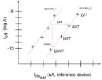
  • introduction of new devices for the 22ULL node: EHVT device, ultra-low leakage SRAM

The 22ULL SRAM is a “dual VDD rail” design, with separate logic (0.6V, SVT + HVT) and bitcell VDD_min (0.8V) values for optimum standby power.

The 22ULL node also get an MRAM option for non-volatile memory.

Note that a new methodology will be applied for static timing analysis for low VDD design. The stage-based OCV (derating multiplier) cell delay calculation will transition to sign-off using the Liberty Variation Format (LVF).

The next generation IoT node will be 12FFC+_ULL, with risk production in 2Q’20. (with low VDD standard cells at SVT, 0.5V VDD).

RF
TSMC emphasized the process development focus for RF technologies, as part of the growth in both 5G and automotive applications. Dr. Jay Sun, Director, RF and Analog Business Development provided the following highlights:

  • For RF system transceivers, 22ULP/ULL-RF is the mainstream node. For higher-end applications, 16FFC-RF is appropriate, followed by N7-RF in 2H’20.
  • Significant device R&D is being made to enhance the device ft and fmax for these nodes – look for 16FFC-RF-Enhanced in 2020 (fmax > 380GHz) and N7-RF-Enhanced in 2021.
  • New top-level BEOL stack options are available with ‘elevated’ ultra thick metal for inductors with improved Q.
  • For sub-6GHz RF front-end design, TSMC is introducing N40SOI in 2019 – the transition from 0.18um SOI to 0.13um SOI to N40SOI will offer devices with vastly improved ft and fmax.

Summary
There was a conjecture/joke going around a couple of years ago, suggesting that “only 7 customers will be able to afford to pursue 7nm designs, and only 5 customers at 5nm”.

Clearly, the momentum behind N7/N6 and N5 across mobile communication, HPC, and automotive (L1-L5) applications dispels that idea. TSMC is investing significantly in enabling these nodes through DTCO, leveraging significant progress in EUV lithography and the introduction of new materials.

Part 2 of this article will review the advanced packaging technologies presented at the TSMC Technology Symposium.

-chipguy

Also read: TSMC Technology Symposium Review Part II


A Quick TSMC 2019 Tech Symposium Overview

A Quick TSMC 2019 Tech Symposium Overview
by Daniel Nenni on 04-26-2019 at 7:00 am

This year TSMC did a FinFET victory lap with the success of 16nm, 12nm, 10nm, and 7nm. It really is well deserved. Even though TSMC credits the ecosystem and customers, I credit TSMC and their relationship with Apple since it has pushed us all much harder than ever before. TSMC CEO C.C. Wei summed it up nicely in his keynote: Innovation, collaboration, and hard work.

Tom Dillinger also attended and he will be writing in more detail next week. Tom has been busy of late. He just finished his second textbook on VLSI Design Methodology Development for Prentice Hall. Remember, Tom started the FinFET discussion on SemiWiki in 2012 so you can bet FinFETs will be mentioned a time or two.

Here is an outline of what Tom will be writing about next week so stay tuned:

Advanced Technology Development and Materials Engineering:
1) N7/N7+ update
highlights: “Making 5G a Reality” — N7 as a technology enabler; D0 defect density improvement; 112Gbps PAM4 SerDes IP

2) N6 update
highlights: PPA comparisons to N7; ease of RTO/NTO migration from N7; new M0 routing (very unique!)

3) N5 update
highlights: schedule; D0 ramp; PPA comparisons to N7; “designed from the start for both mobile and HPC platforms”

4) Advanced process development / materials engineering
highlights: additional Vt devices for HPC in N5 and ULL/ULP technologies; high mobility (Ge) channel device; metal RIE (replacing damascene patterning); new metallization materials (graphene cap on Cu); future research into 2D semiconductor materials

5) Manufacturing excellence
highlights: focus on in-line process monitoring; maverick lot identification; “ink out good die in a bad zone” (very unique!); Continuous Process Improvement focused on wafer edge (very unique!); product-specific UpperSpecLimit + LowerSpecLimit statistical process control (also very unique!)

6) Roadmap for automotive platform
highlights: new “L2+” automotive grade introduced; focus on DPPM reduction; MCU’s in a vehicle transitioning from eFlash to MRAM memory offering

7) Roadmap for IoT platform
highlights: new eHVT device; unique analog device process engineering; new “dual-rail VDD” SRAM offerings (aggressive SRAM_Vmin scaling); MRAM roadmap

8) RF process development focus
highlights: device engineering to improve ft and fmax (in several processes), new thick metal to improve inductor Q factor; device model characterization

Although the specialty technologies presentation was very interesting, there’s probably not enough room in the article to cover MEMS, CIS (at near infrared wavelengths), etc.

“Front-End” and “Back-End” Advanced Packaging:
1) SoIC
highlights: diverse die size and stacking options (e.g., face-to-face and face-to-back bonding)

2) CoWoS
highlights: reticle size roadmap, embedded deep trench caps (DTC) in Silicon interposer

3) InFO
highlights: InFO_PoP through InFO via (TIV) scaling; InFO without substrate (2020)
4) 3DIC ecosystem support

History is always a part of semiconductor symposiums because semiconductors really have come a long way fueled by a series of technological disruptions. When I went away to college my beautiful girlfriend (wife) used to write letters to me everyday and call me on the weekends. My parents and grandparents had similar experiences. Shortly after we married, PCs and the internet landed on our desks and we emailed and Usenet-ed our way around the world. Then came smartphones and social media, probably the biggest disruption of them all. Phones are now in our hands and faces more than ever before but that is going to change.

The next disruption will be fueled by 5G and AI which is just now beginning. If you think semiconductors are important today just wait another ten years because you will not be able to survive without them, absolutely.

TSMC and the semiconductor industry have been living a very mobile life since PCs and phones left our desks. Moving forward, AI enabled edge devices will continue to be a semiconductor industry driver but the real upside for the foundry business will be getting the many zettabytes of data into the cloud and processed. Today Intel CPUs and GPUs dominate the cloud. Tomorrow it will be custom AI processors built by the cloud companies themselves in close partnership with the fabless semiconductor ecosystem and that means TSMC.

From writing letters to “real-time thought processing” in one lifetime, simply amazing.

Also read: 2019 TSMC Technology Symposium Review Part I


TSMC Q1 2019 Earnings Call Discussion!

TSMC Q1 2019 Earnings Call Discussion!
by Daniel Nenni on 04-19-2019 at 7:00 am

It’s no coincidence that the TSMC Symposium is right after the Q1 earnings call. This will allow TSMC to talk more freely and they certainly will, my opinion. It is a very interesting time in the semiconductor industry and TSMC, being the bellwether, can tell us what will happen the rest of the year and give us some 2020 insights.

TSMC CEO C.C. Wei again led the call with a prepared statement. This time I will paste the entire statement (minus the packaging stuff) with my embedded comments.

  • Thank you, Lora. Good afternoon, ladies and gentlemen. Let me start with our near-term demand and inventory. We concluded our first quarter with revenue of TWD 280.7 billion or USD 7.1 billion, in line with our revised guidance. Our business in the first quarter was impacted by three factors: first, the overall global economic condition, which dampened the end market demand; second, customers are ongoing inventory adjustment; and third, the high-end mobile product seasonality. Meanwhile, the net effect from the photoresist defect material incident also impact our first quarter revenue by about 3.5%.

My question here is: Who is liable for this defect? Is the supplier being held accountable? Accounts of this incident from South Korea painted TSMC as negligent which I have found to be fake news.

  • Moving into second quarter this year. While the economical factor and mobile product seasonality still linger, we believe we may have passed the pattern of the cycle of our business as we are seeing customers’ demand stabilizing. Based upon customer indications for their business and wafer loading in second quarter, we also expect our customers’ overall inventory to be substantially reduced and approach the seasonal level around the middle of this year.

Personally, I feel the second quarter will be stronger than expected based on 2018 year end CEO comments. It is better to under predict than over predict and I believe that is what is happening here. Let’s not forget the Q1 2019 semiconductor guidance we previously published:

  • In the second half of this year, TSMC’s business will be supported by this year’s inventory base as well as strong demand from our industry-leading 7-nanometer technology, which support high-end smartphone new product launches, initial 5G deployment and HPC-related applications. For the whole year of 2019, we forecast the overall semiconductor market is good in memory as well as foundry growth to both be flattish. For TSMC, we reiterate that we expect to grow slightly in 2019.

To me this is low single digits but closer to 5% than 1%. Here are the previously published analyst forecasts for 2019:

  • Now let me update the photoresist material incident. On February 15, in order to ensure quality of wafer delivery, TSMC announced it will scrap a large number of wafers as a result of a batch of bad photoresist material from a chemical supplier. This batch of photoresist contain a foreign polymer that created a desirable – undesirable effect and resulted in yield deviation on 12-and 16-nanometer wafers at Fab 14B.
  • We have since taken corrective action to enhance our defenses and minimize future risk. Our actions including the following: improved TSMC’s own in-house incoming material, conforming test and controls; upgrade control and methodology with all suppliers for incoming material quality certification; establish robust in-line and off-line monitoring process to prevent defect escape.

TSMC does not point fingers but again I would like to know more about this event.

  • Now I will talk about our N5 status. Our N5 technology development is well on track. N5 has entered risk production in first quarter, and we expect customer tape-outs starting this quarter and volume production ramp in first half of 2020. With 1.8 times logic density and 15% speed gain and an ARM A72 core compared with 7-nanometer, we believe our N5 technology is the most competitive in the industry. With the best density performance, power and the best transistor technology, we expect most of our customers who are using 7-nanometer today will adopt 5-nanometer. With N5, we are expanding our customer product portfolio and increasing our addressable market. Thus, we are confident that 5-nanometer will also be a large and long-lasting node for TSMC.

To be clear TSMC 5nm chips will be in Apple products next year. I have read reports that TSMC released 6nm because 5nm was late which is fake news. I know many companies that are taping-out at 5nm and it is on track and meeting expectations. More details will be available on SemiWiki after the symposium so stay tuned.

  • Now I’ll talk about the ramp up of N7 and N7+ and introduction of N6. We are seeing strong tape-out activity at N7, which include HPC, IoT and automotive. Meanwhile, our N7+, which adopts EUV for few critical areas, has already started volume production now. The yield rate is comparable to N7. We’ll reaffirm N7 and N7+ will contribute more than 25% of our wafer revenue in year 2019.

If you look at TSMC’s Q4 2018 revenue split, 50% is FinFET processes and 50% is mature CMOS nodes. In Q4 2017 FinFET processes were 45% and in Q4 2016 it was 33%. In Q1 2019 FinFET revenue dropped to 42%, not a good sign, let’s blame cryptocurrency.

  • As we continue to improve our 7-nanometer technology and by leveraging the EUV landing form, N7+, we now introduce N6 process. N6 has three major advantage. First, N6 have 100% compatible design rules with N7, which allows customer to directly migrate from N7-based design, which substantially shorten the time-to-market. Second, N6 can deliver 18% higher logical density as compared to N7 and provide customer with a highly competitive performance-to-cost advantage. Third, N6 will offer shortened cycle time and better defect density. Risk production of N6 is scheduled to begin in first quarter year 2020 with volume production starting before the end of 2020.

N6 is a little bit confusing thus far. Hopefully we can get it cleared up at the TSMC Symposium. From what I understand N7 and N7+ are not design rule compatible since N7+ has EUV. N6 is N7+ with an additional layer of EUV which helps with density. Saying N6 and N7+ are design rule compatible makes sense but is N6 really design rule compatible with N7?

  • Finally, I will talk about the HPC as our most important growth driver in the next five years. CPU, AI accelerator and networking will be the main growth area for our HPC platform. With the successful ramp of N7, N7+ and the upcoming N6 and N5, we are able to expand our customer product portfolio and increase our addressable market to support applications, such as data center, PC and tablets. Meanwhile, we also see networking querying thanks to 5G infrastructure deployment over the next few years. We are truly excited about our growth opportunities in HPC. Thank you for your attention.

AI is a trending term on SemiWiki and readership is all over the map. I seriously doubt it will be a quick bubble like cryptocurrency or even a 10 year bubble like mobile. In my opinion AI will be with us for a very long time and it will consume leading edge wafers like a zombie apocalypse, absolutely.

From what I have heard EUV throughput is still ramping up so my fingers are crossed for 5nm. Hopefully EUV is covered in more detail next week at the TSMC Symposium. I will also get a refresh from our resident EUV expert Scott Jones. In fact, he has just posted an EUV blog from SPIE:

SPIE Advanced Lithography Conference – Imec and Veeco on EUV

Bottom line: The second half of 2019 will be good for TSMC and 2020 will be even better. My prediction today for TSMC in 2020 is back to double digit growth. Remember, now that Intel is out of 5G modems TSMC will get the modem business back from Apple next year via the 7nm QCOM modem plus other 5G modem business. 2020 will be the beginning of a beautiful 5G friendship.