 If a picture worths a thousand words, a tapeout quality SoC design with billions of polygons would compose a good book. To proofread this final design transformation format requires a foundry driven DRC/LVS signoff solution that nowadays is becoming more complex with further process scaling and shrinking pitch dimension.
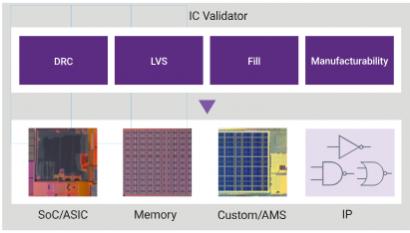
Despite being frequently considered as the long pole in the tapeout cycle, physical verification step provides the needed critical assurance to a silicon success. As a leader in the physical verification (PV) domain, Synopsys IC Validator provides a comprehensive DRC/LVS signoff solution that delivers shorter time-to-results while supporting scalability, ease-of-use and ample runset coverage across various process nodes.
Tool Integration
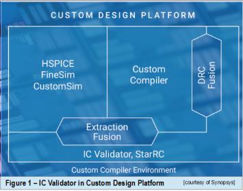
Depending on its application context, IC Validator can be used in conjunction with different adjoining tools. For example in the custom design environment, it is integrated through Extraction Fusion and DRC Fusion –as part of the Synopsys Custom Design Platform along with other design and verification tools such as HSPICE, FineSim, CustomSim for circuit and reliability analysis, Custom Compiler and StarRC parasitic extraction. The intent of such tight integration is to accelerate custom and AMS design development. The Custom Design Platform is based on the popular OA (OpenAccess) database. It includes a complete set of open APIs for third-party tool integration as well as Tcl and Python programming support. 
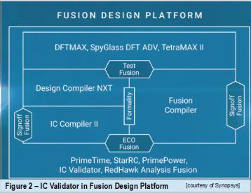
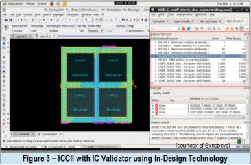
On the other hand, IC Validator also complements the Fusion Design Platform as a signoff element. Its seamless integration with IC Compiler II place and route system has enabled designers to perform independent signoff-quality analysis and automatic repair within ICC II –a process known as In-Design physical verification.
Customer shared challenges and experiences
In general, we could categorize three major selection criteria for a good physical verification solution, namely: total turnaround time, capacity and coverage support to foundry driven DRC/ERC analysis or fixing.
As an IC Validator adopter, IBM has utilized IC Validator Explorer –a DRC feature, to perform about a thousand basic checks in the shortest time possible. The check took 5 hours using only 8 processors, a much shorter verification compared with its corresponding full-chip DRC job involving 15.7K checks plus 160 processors and hours of runtime. Such precursor, stand-alone IC Validator Explorer run was done to evaluate design data integrity without the potential risk of hitting an incomplete job due to unintended, injected setup or basic errors such as misplaced units, P/G shorts, incorrect library. Only after a successful completion of such initial run, a full DRC is kicked off.
With respect to scalability, IC Validator turnaround time has also been proven to be quite linear. Another customer, SocioNext had confirmed scalability performance of 2.95x with 3x CPUs.
Metal Fill and DRC Related Fixes
In order to satisfy foundry requirement –which relates to retaining uniformity in metal density post CMP, metal fill has become a key element in tapeout preparation. There are two mainstream approaches, a shape based foundry fill and track based metal fill. Failure to apply proper metal fill may translate to an adverse timing impact depending on the inclusion or exclusion of the adjacent layer of the fill to the capacitance (which could shift by 10% or more).
Track based metal fill tends to deliver higher density while not requiring a runset as in the case of foundry based fill (instead, it is a techfile based). Additionally, the timing aware, color balanced track based fill generates a better yield, since regular shapes makes lithography patterning more consistent. Designers have finer and tighter density control, such as layer-by-layer control and defining window size target per layer. The density controlled is intended to balance DFM design rules and timing.
 Using IC Validator with In-Design Technology allows an incremental and automated fill post ECOs. The tool identifies and performs fill on changed areas or layers. It is fast and natively done in NDM, requiring no streaming or tool setup. Fill removal around timing critical nets also preserves timing.
As the types of DRC related analysis and fixing are increasingly diverse, there are more acronyms and terminologies introduced over the course of few process nodes rollout –including the following terms:
- ADR (Automatic DRC Repair), in which Synopsys Zroute is called to fix the DRCs and minimal impact to route topology or timing changes;
- PERC (Programmable Electrical Rule Check), a feature in IC Validator that enables designers to validate new class of mixed-mode checks by combining netlist checks with geometric checks;
- PM (Pattern Matching), a rule-based signoff feature for pattern-driven verification. It enables quick identification and perform subsequent automatic correction of potential manufacturability hotspots in a design by comparing them against a library of known problematic layout patterns.
IC Validator Landing Page
The examples discussed above represent some snapshots of how designers could tap IC Validators functionalities. To further facilitate such a growing list, Synopsys PV team has created a media collage of IC Validator related to flow customization, customer experiences and quick tips and how-to here. The collection is comprised of short videos of few minutes to no more than 5 minutes long.


Comments
There are no comments yet.
You must register or log in to view/post comments.