

Designing custom IP blocks is a challenge at the transistor-level and I wanted to learn what the recommended methodology and EDA tool flow was at Synopsys. They have a webinar that you can register for and it takes 30 minutes to learn what they have to say, or you can read a White Paper. If you cannot spare that much time, then my summary should answer some of your initial questions in about 10 minutes.

Bradley Geden, Solution Architect
Technology Trends
- wire widths decreasing as nodes get smaller
- total interconnect length is increasing
- current density increasing, non-proportional
Electromigration (EM)
- Gradual displacement of metal atoms in a semiconductor
- When current density gets too high, causing drift of metal ions
- Depends on conductor, crystal size, interace and grain-boundary chemistry, magnitude of forces, temperature, mechanical stresses
Failure Mechanisms
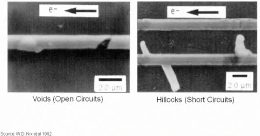
- failures caused when there is an asymmetry in the ion flow
History of EM
- Known for 100 years
- 1966 interest in EM for IC designs
- Jim Black at Motorola, “Blacks Equation” for Mean time to failure
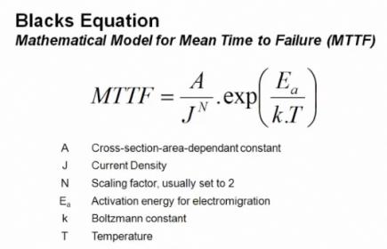
EM and Temperature
- MTTF is a function of temperature
- Irms contributes to increases in termperature, thermal run away
EM and Wire Width
- Increase the wire widths to reduce EM
- If wire is thinner than grain boundary it improves MTTF
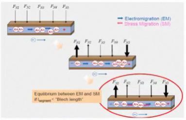
EM and Wire Width
- Blech-length: lower limit for the length of interconnect that will allow EM to occur
Physical Layout Tips to Avoid EM
- Avoid 90 degree corners on high current nets
- Even distribution of multiple vias
EM Analysis – Design
- Parasitic Extraction (don’t reduce Resistors or Vias)
- EM Testbench (use worst case currents – Average, RMS, Peak)
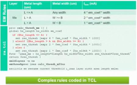
Foundries have Complex EM Rules on Metal Layers (width and length dependent), so use Tcl to define these rules:
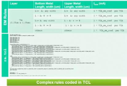
EM Rules for Via layers are more complex than Metal Layers:
Analysis Recommended – Static Net Resistance Check using CustomSim-RA
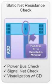
- Power bus check
- signal net check
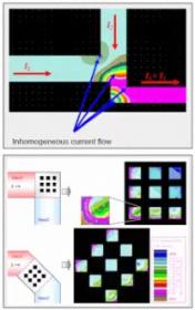
- visualization
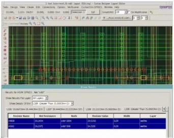
Show me all nets with R>25 ohms
Dynamic Current Simulation (run after the static net resistance check) using CustomSim (HSIM) for the high capacity and faster circuit simulation times:
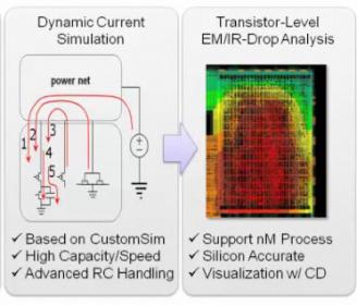
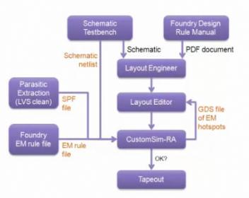
The dynamic analysis tool flow:
Inputs and outputs of the dynamic analysis tool flow:
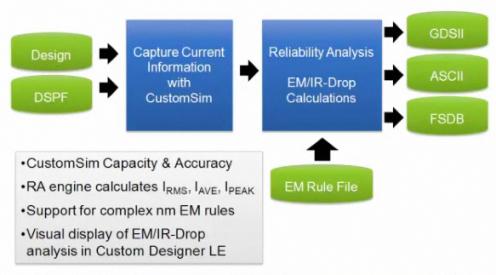
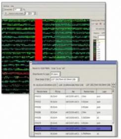
You can visualize the EM and IR results or just read an ASCII text file. Cross-probing supported between text results and IC layout view.
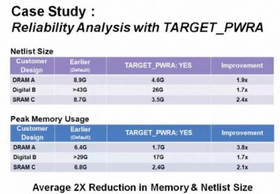
With extraction by StarRC you use a macro option “TARGET_PWRA: YES|NO” to get an optimized flow.
Real customers shared their experiences at SNUG.
- TSMC – Used Tcl for rules, see: “Hybrid IR/EM Analysis Flow with EM Rule Extension”, Gary Chan, TSMC; 2011 Synopsys User Group (SNUG) Conference, Taiwan
- NVIDIA – Used CustomSim on their GPUs for EM and IR validation flows.
Questions from Attendees
- Q: Have there been much change moving from Aluminum to Copper for ER and IM?
A: Yes, the Copper is about 5X more tolerant than Aluminum. - Q: What is the most accurate IR drop analysis?
A: We recommend both a static and dynamic analysis flow while coupling both logic and power/ground networks. On large designs we recommend a de-coupled flow. - Q: What can I expect moving from HSIM to CustomSim-RA flow?
A: We originally used HSIM and now recommend that you use CustomSim instead for EM and IR analysis, it’s more accurate and faster.
Summary
Synopsys has all of the EDA tools to let you layout a custom IC block, analyze EM and IR effects, then tweak the IC layout to pass the foundry rules. CustomSim-RA is the tool name for Reliability Analysis. With the acquisition of Magma I have to wonder where FineSIM Pro will fit into this tool flow, if at all.
Competitor EDA tools in this space include: Cadence (Virtuoso UltraSim), Mentor (Electromigration check with Eldo) and Apache/Ansys (Totem MMX). Synopsys tools would go head-to-head with Cadence because both companies have a high-capacity circuit simulation engine, while Mentor’s circuit simulator can only be used for smaller IP blocks. The Apache approach to EM and IR is similar to Synopsys, however Apache doesn’t offer the IC layout tools.
I would hope that the foundries would include and qualify the Synopsys Tcl equations in the PDK to enforce the reliability rules.
Share this post via:


Comments
0 Replies to “IC Custom IP Blocks – EM and IR Drop Effects”
You must register or log in to view/post comments.