Increasing system complexity requires constant focus on the optimal verification methodology. Verification environments incorporate a mix of: transaction-based stimulus and response monitors, (pseudo-)random testcase generation, and ultimately, system firmware and software. RTL statement and assertion coverage measurement is crucial. Power domain verification is required, with functionality described in both RTL and power format file descriptions. Power dissipation estimates help guide both system architects and implementers. In-circuit emulation (ICE) features are required to exercise the model with external peripherals.
These requirements all underscore the need for faster simulation throughput. It’s evident why the EDA market for simulation acceleration technology is growing rapidly.

On that topic, Frank Schirrmeister was gracious enough to share his insights. Frank is Senior Group Director, Product Management, for the Cadence System and Verification Group. Cadence is uniquely positioned in both simulation acceleration domains – processor-based emulation and FPGA-based prototyping.
Initially, Frank addressed a question that has been puzzling (to me, at least): “What is the difference between emulation and prototyping?”
Frank provided a unique perspective. “It comes down to customer expectations. If the RTL design contains (synthesizable) constructs appropriate for the emulation platform, a system model should automatically compile on Cadence’s Palladium-XP. If it doesn’t, that’s a bug – call us. Conversely, developing a prototype model on an FPGA platform typically requires significant manual intervention to optimize the implementation. That effort may include partitioning the model across FPGA’s, managing clock domains, or completing FPGA physical design and timing closure.”
He then described an alternative approach. “Cadence provides the FPGA-based Protium platform with emulation-like automation, to reduce the time and resource typically associated with prototyping.”

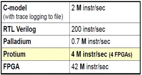
The figure illustrates a recent customer’s experience across the gamut of accelerated simulation technologies, with performance data from:
- a C-based model
- the PalladiumXP emulation platform, and
- a highly-optimized FPGA prototype board the customer developed internally
(Reference: SRISA, CDNLive-EMEA, 4/27-29/2015).
The Cadence Protium FPGA-based platform was then introduced, applying the “Palladium adjacent” flow to automate model compilation and physical implementation. Although performance was less than the highly-optimized prototype board, the fast model bring-up on Protium was a huge win for the customer, in both schedule and resource.
Frank indicated that additional model performance improvements on Protium are certainly supportable, with the manual optimizations described above. Yet, the Palladium-adjacent flow offers customers the benefits of emulation, followed by the performance improvement of Protium.
More from Frank shortly, but a little background might be helpful…
There are two main technical approaches to hardware-assisted verification, augmenting software simulators:
(1) processor-based emulation
An array of custom-designed processors provides functional emulation of a system model. Conceptually, these processors evaluate a large concurrent set of Boolean operations – i.e., each processor is comprised of thousands of general-purpose logic units. The sequence of instructions to these units are defined and synchronized as part of model compilation. System state and memory array values are stored, based upon the “reference clock” (which is not the actual hardware clock frequency for compiled model execution on the processors).
The platform provides high visibility and trace recording, across moving time windows.
A workstation is attached for job control, and for execution of testbench functionality not compiled into the accelerator.
Physical interfacing is supported by a rate-adapting card between the emulator and a peripheral, to compensate for bandwidth differences – a number of “SpeedBridges” are offered by Cadence for standard interfaces.
(2) FPGA-based prototyping
A prototyping system consists of a number of FPGA modules (and memory) programmed to implement the model. SpeedBridges may be connected, as well.
The compilation process is more involved, as mentioned above. Internal model visibility for tracing is more limited, often requiring signals to be identified during model compilation.
The prototyping platform model capacity can be unpredictable, as it depends on:
- (datapath/arithmetic/control) logic functionality and the FPGA slices available
- clock domain definitions and the internal FGPA clock resources
- conversion of model register files to internal FPGA storage, and
- the target timing and the FPGA local/global signal buffering resources available
Conversely, internal FPGA slice utilization can be high, yet the FPGA pin count is a limiting factor. In these cases, time-multiplexing of I/O communication between modules is used.
The prototyping platform is not targeted for a transaction-based verification environment, which would adversely impact throughput. The performance of the platform is best suited for a full system model — “a DUT in a box” — to exercise system firmware/software.
Frank offered some details on the Protium “FPGA-based emulation” methodology. A common front-end model compilation flow (“HDL-ICE”) is used, to ensure compatibility. The next flow step splits, either mapping to PalladiumXP or to Protium (using Cadence partitioning and Xilinx Vivado implementation tools). The key is that Cadence guarantees Protium model functionality with the same support as PalladiumXP.
In summary, when an RTL model is less stable, the unique advantages of emulation are leveraged:
- speedup over software simulation, with high trace visibility
- CPF/UPF power domain checks synthesized into the model
- Dynamic Power Analysis (DPA) is integrated with Cadence Joules, with toggle counts now available from testbenches only feasible to run on an accelerator
- emulation coverage data can be merged with that from software simulation, in the Cadence “big data” Metric Center
As the RTL model stabilizes, the transition to “FPGA emulation” with the DUT-in-a-box model provides an efficient path to achieving performance suitable for firmware/software development and debug.
Cadence’s product portfolio for simulation acceleration, combined with the “Palladium adjacent” flow offers a unique methodology. From a cost perspective, it strikes me that this allows managing concurrent verification projects effectively. Rather than requiring capacity for two projects in a single platform, verification would transition from emulation to prototyping in a pipelined manner, to offer the best of both worlds. Having both platforms available introduces some interesting post-silicon debug model verification options, as well.
-chipguy
Share this post via:


Comments
0 Replies to “What’s the Difference between Emulation and Prototyping?”
You must register or log in to view/post comments.